
Abstract
In the research process of automotive active steering control, due to the model uncertainty, road surface interference, sensor noise, and other influences, the control accuracy of the active steering system will be reduced, and the driver’s road sense will become worse. The traditional robust controller can solve the model uncertainty, pavement disturbance and sensor noise in the design process, but cannot consider the performance enough. Therefore, this article proposes an active steering control method based on linear matrix inequality. In this method, the model uncertainty, road interference, sensor noise, yaw velocity, and slip side angle tracking errors are all considered as constraint targets, respectively, so that the performance and robust stability of the active front steering system can be guaranteed. Finally, simulation and hardware in the loop experiment are implemented to verify the effect of active front steering system under the linear matrix inequality controller. The results show that the proposed control method can achieve better robust performance and robust stability.
Introduction
The active front steering system (AFS) of an automobile plays an important role in ensuring vehicle safety.1,2 On the basis of vehicle state, the AFS will provide a superposition angle between the steering wheel and the front wheel to modify the steering input of the driver’s steering input. AFS can be applied to the research of path tracking and emergency avoidance, 3 which is significant to the realization of intelligent driving. Therefore, scholars have done many kinds of research on it.
During the research, the AFS performance, the vehicle stability, the model uncertainty, and the interference problems are mainly concerned, and all kinds of advanced control methods and research schemes have been successively applied to improve the overall performance of AFS.
There has been more research aimed at improving the AFS performance and the vehicle stability. Mazuan bin Mansor et al. 4 paid attention to the performance of AFS and built the 14-degree-of-freedom (DOF) model of an armored vehicle to ensure the accuracy of the model. Proportion–integration–differentiation (PID) controller was used to dynamically correct the turning angle, which showed good performance. K Huh and J Kim 5 proposed an active steering control method based on fuzzy logic rules of tire lateral force estimation by compensating the deviation between the real-time estimation value of tire lateral force and the reference value by the active steering controller.
However, the aforementioned methods are highly dependent on the model and cannot effectively deal with the influence of model uncertainty on the control performance of AFS. Then, P Falcone et al. 6 and Y Yoon et al. 7 proposed the model predictive control (MPC) method to improve the performance of AFS through real-time prediction of the tracking path during the control process which could ensure good stability of the vehicle under different speeds and tracks. T Fukao et al. 8 proposed a model reference adaptive nonlinear control strategy for AFS by taking nonlinearities and uncertainties of tires as well as the friction of the road into consideration, which could obtain a satisfactory control results under critical situation.
At the same time, the existence of road surface interference and sensor noise can make AFS control difficult. Therefore, a robust control method has been successively applied in the research of AFS. On the basis of driver intention recognition, X Ji et al. 9 proposed a robust control method based on normalized left mutual quality decomposition. The single-step method is used to improve the robustness of the active steering system. To solve the conflict between performance and stability, J Wu et al. 10 proposed a generalized internal model control method (GIMC) including a high-performance controller and a compensating robust controller to ensure the performance and the stability for AFS. Cheng et al. 11 proposed an active safety control by estimating the side slip angle with a estimator based on adaptive square-root cubature Kalman filter (ASCKF) to improve the vehicle stability. W Zhao et al. 12 designed a hybrid H2/H∞ robust controller considering tire nonlinearity and external interference. The robustness is controlled by H∞, and performance is monitored by H2. J Feng et al. 13 put forward a rolling time-domain control method. The vehicle yaw deviation is taken as the input of the linear quadratic regulator model in the rolling time domain, and the real-time superposition angle is calculated and applied to the vehicle model, which can effectively compensate for the uncertainty and interference caused by the model mismatch.
In order to further discuss the aforementioned problems, many scholars explored the integrated control based on AFS. B Zhou et al. 14 proposed an integrated control system of AFS and electric power steering (EPS) including the compensation for the change of steering wheel torque caused by the intervention of AFS. Many previous studies15–23 have integrated the yaw torque control or brake control into AFS with different control methods to increase the stability of the vehicle. Ji et al.24,25 pay attention to the vehicle stability based on AFS mainly using adaptive neural network–based method which gets a good result. Although the integrated control can make the vehicle more stable, it increases the complexity of the system and affects the execution efficiency of the system to a certain extent.
Many control systems including AFS need to deal with multi-objective constraint problem, which is difficult for the aforementioned algorithms. As linear matrix inequality (LMI) can take all control targets into consideration by establishing Lyapunov function, a series of control method based on LMI is proposed. L Menhour et al. 26 proposed a two-PID control method based on LMI theory. It can get a good control effectiveness but may suffer from the uncertainty as the controller is designed based on linear time-invariant models. G Yin et al. 27 designed an H∞ robust optimal controller and an H∞ robust non-fragile controller based on LMI to process both the control and robust performances as well as the fluctuation of controller parameters to apply on four-wheel steering (4WS) and four-wheel driving (4WD) control. It is a good example of using the LMI. Then X He et al. 28 applied LMI to active steering control by taking the lateral path-tracking bias and course deviation as well as uncertain external disturbances into consideration to realize the robust coordination control of AFS and active rear wheel steering (ARS). But they are concentrated on the path tracking capability. However, there is a lack of direct investigation on the control of yaw velocity and side slip angle, especially because the change of yaw velocity and the side slip angle are not synchronous at limit condition, which may influence the stability of the vehicle. Therefore, this article proposes an LMI control method by establishing error model including both yaw velocity and side slip angle deviation which is applied on AFS to solve the problem.
The research in this article is mainly divided into the following parts: the first part is to establish the vehicle dynamics model and error model. The second part designs the active steering controller based on LMI. The third part conducts the controller simulation experiment. In the fourth part, the hardware-in-the-loop (HIL) implementing scheme is designed and the experiment is carried out. Conclusions and future tasks are given in the fifth part.
The parameter variables used in this article are as shown in Table 1.
Parameter variables.

Model and problem descriptions
Control structure
The integrated control structure is shown in the Figure 1. The ideal yaw angular velocity ωrd and ideal side slip angle βd can be obtained from the 2-degree-of-freedom (2DOF) vehicle model according to the driver input steering angle δ. The real values ωr and β could be obtained from the vehicle model. The deviation could be obtained and used to establish the error model and the system model. Then, LMI controller is derived, and the superposition angle could be obtained to apply on the vehicle model adding to the driver steering wheel inputting angle.
The control structure of LMI.
Research workflow
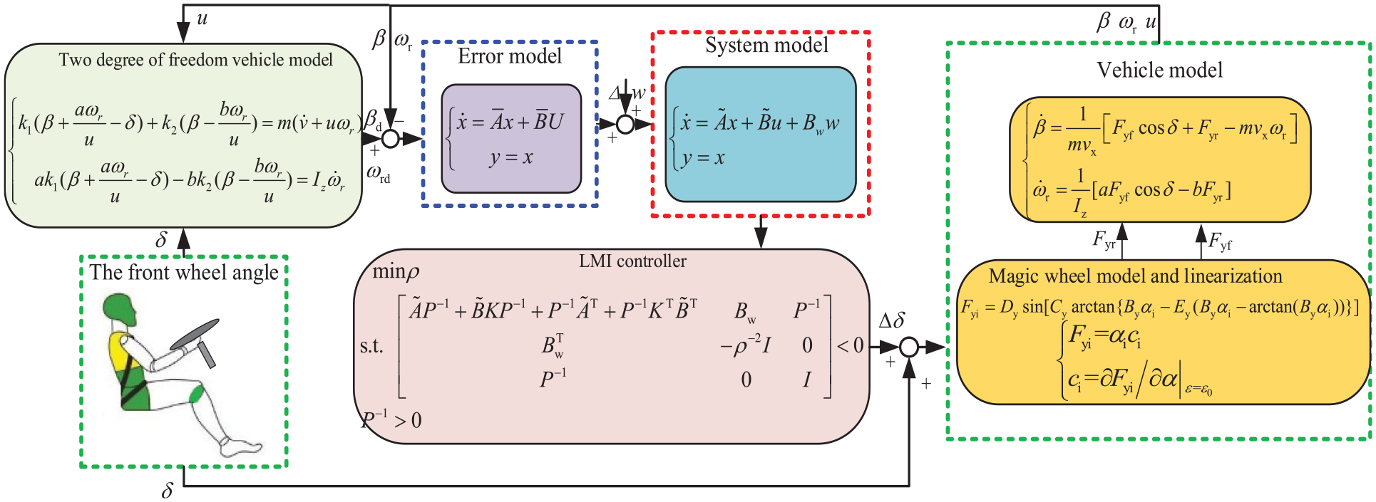
The whole research process can be summarized as the following block diagram in Figure 2.

A schematic representation of the research workflow.
In the research process, the model uncertainty, road interference, sensor noise, yaw velocity, and slip side angle tracking errors are all considered to establish the model. The LMI controllers then are derived to solve the aforementioned problems. Finally, simulation and HIL experiment are implemented to verify the effect.
2DOF model and control target acquisition of the vehicle
The 2DOF model of the automobile shown in Figure 3 is adopted as the ideal reference model, which can reflect the relationship between steering wheel angle input, yaw velocity, and side slip angle output.

Two-degrees of freedom vehicle model.
The 2DOF dynamical equation can be expressed as follows 8

Select state variables

Among them

In this article, a 2DOF model and a magic tire model are combined as the actual vehicle model, which can largely reflect the actual working conditions to some extent. The actual basic state response of the vehicle can finally be obtained.
The 2DOF model of the automobile can also be expressed by the following expression

Tire model
The magic tire formula is considered, as it comprehensively consists of the transverse, longitudinal, lateral, and other motion states of the tire under various conditions.
The lateral deflection force of the front and rear wheels can be expressed as 11
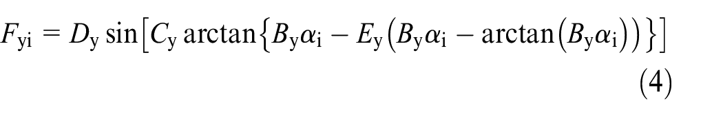
where i stands for f and r, respectively, αi represents the front and rear wheel side deflection angle of the tire, By is the stiffness coefficient, Cy is the curve shape factor, Dy is the peak factor, and Ey is the curvature factor.
And

The relevant parameters can be obtained through experiments which are adopted in Table 2.
Magic tire formula parameters.

For the sake of derivation and calculation, the following assumption is made in this article: the vehicle’s rotation angle is small. The tire side angle is obtained by relevant parameters which are shown as

where αf and αr are the front and rear wheel side declinations, respectively.
Magic tire model is a nonlinear model, which makes it very difficult to solve. Therefore, this article linearized the tire magic formula as

Establishment of an error model
By substituting the aforementioned magic tire model into the 2DOF vehicle model, the nonlinear actual model, the actual yaw velocity, and side slip angle can be obtained, and the state space can be expressed as

where

At the same time, this article defines the error model which can be shown as

The form of the state space of the error model is


where y is the output of the system. The controller designed in this article needs all the outputs to control the tracking error.
Considering model uncertainty, sensor noise, and pavement interference, the state space can be further expressed as

where w represents sensor noise and pavement interference,

where G0 is the pavement interference coefficient.
ΔA and ΔB represent model uncertainty and parameter changes which satisfy

According to the decomposition method proposed by Li and Jinwen, 29 ΔA(t) can be broken down as follows


where xij represents the elements row i and column j, ΔA and ΔB represent the 20% fluctuation of the value in the system matrix, ei is the unit vector where the ith row entry is 1, and the rest of the entries are 0. F(t) reflects the influence of these nonlinear relations on the system equation of state. And F(t) can be obtained according to Hu et al. 30

It is the same with ΔB(t).
A system considering model uncertainty can be expressed as

Controller design based on LMI method
The robust feedback control law of the aforementioned system can be expressed as

K represents the state feedback gain matrix.
Choose Lyapunov equation as

Put the formula (15) into Lyapunov equation and solve its differential equation to get the following formula

Let
Then the previous equation can be changed into

Define
Let
In the previous formula


By combining the two formulas (20) and (21), we can get equation (22)

In order to ensure that the system has a strong anti-interference and the ability to suppress noise, namely, minimize the impact of outputs suffered from interference and noise, the H∞ performance indicator ρ is set as follows

Among them, ρ shows the resistance to interference and noise and it is the smallest possible value greater than 0. The derivative with respect to t is going to be the following

Combine the two formulas (22) and (24), we obtain

The stability of the system is determined by this formula, so the robust and stable system is determined by the following inequality

Then

The integral of equation (27) is obtained as follows

Combining formulas (17) and (28), we can get

The deformation can be

Therefore, when
According to Schur complementary lemma, 30 formula (26) can be transformed as follows

Substitute expressions (18) and (20) into the inequality equation (31) to get the following linear inequality

Multiply both sides of this equation by
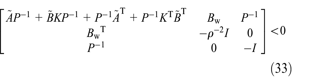
So that the previous equation satisfies the following LMI
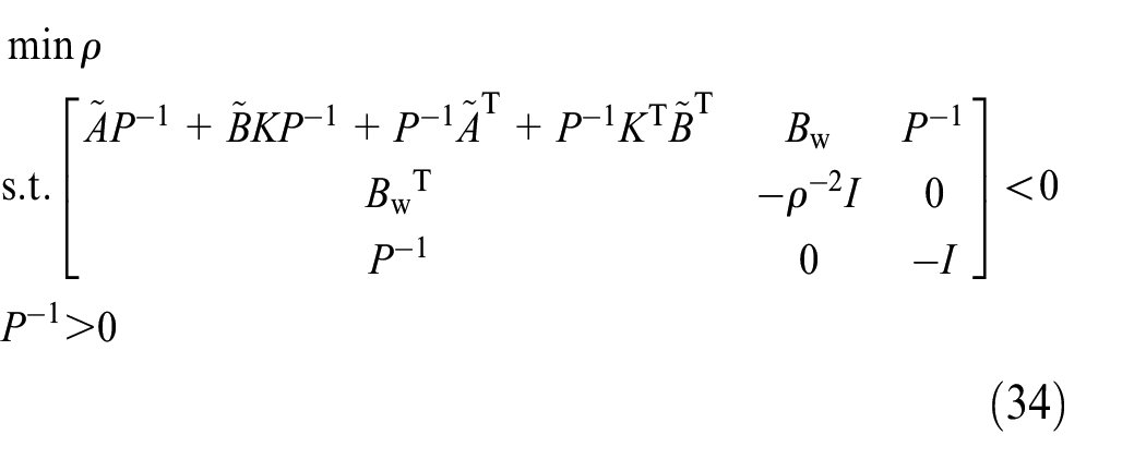
Use the YALMIP toolbox in MATLAB to solve it, and we can get the corresponding parameter ρ and vehicle active steering state feedback controller K.
Simulation test
In this article, the desired yaw velocity and side slip angle are generated by the 2DOF vehicle model, and the LMI active steering controller is derived. The Carsim can generate a front wheel angle when following the path, and the LMI controller can generate a superimposed rotation angle. Moreover, the actual yaw velocity and side slip angle can be obtained from the sum angle vale. Then, the deviation from the desired value and the real value are fed back to the controller to form a closed-loop control.
As shown in the Figure 4, the vehicle speed is set at 120 km/h in the double lane change (DLC) path, and the vehicle state parameter curves under LMI control, PID control, and uncontrolled are compared and analyzed, respectively. Figure 4(a) shows the lateral displacement under the three kinds of control. It can be seen that the path-tracking delay is large, and the resulting path is steeper without AFS, which can obviously indicate that the vehicle is unstable. However, both LMI control and PID control can make the vehicle gradually return to the central path, but the path overshoot under LMI control is smaller and the oscillation time is shorter. Figure 4(b) is the comparison for steering wheel angle, where we can clearly observe that it reaches the position limit at 6–7 s and 11–13 s without AFS which makes it hard to control the vehicle. The steering wheel angle under PID control can stay in a reasonable range. Moreover, it has a better response ability under LMI control, nearly 1 s faster than the response under PID control.
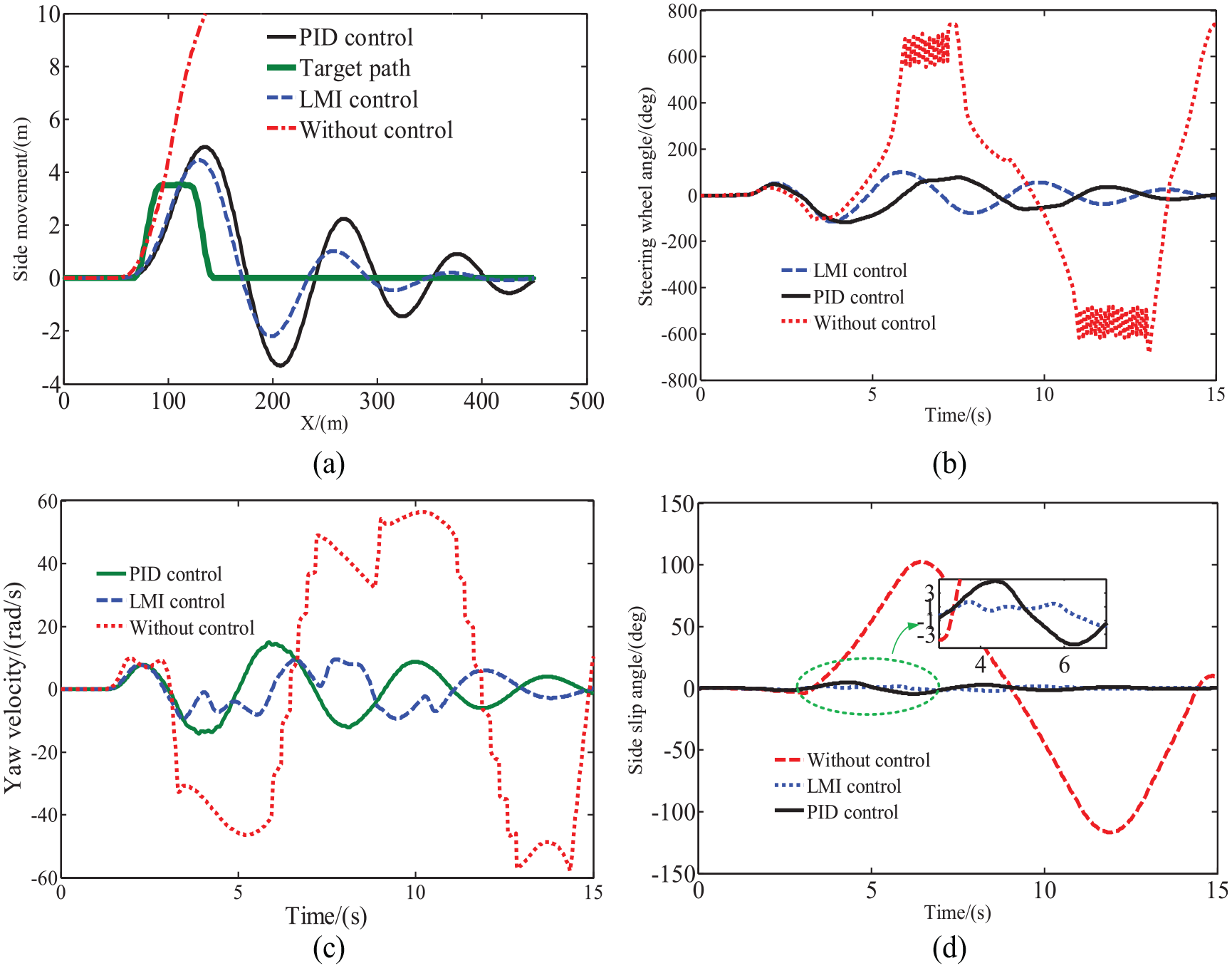
Vehicle state parameter: (a) lateral displacement, (b) steering wheel angle, (c) yaw velocity, and (d) side slip angle.
Figure 4(c) shows the comparison of yaw velocity. It can be clearly observed that the yaw velocity changes sharply without control. The yaw velocity response is better under PID control, but the oscillation time is long. In comparison, the overshoot under LMI control is small and the oscillation period is shorter. As shown in the Figure 4(d), the vehicle has a very large side slip angle without AFS, which means the vehicle has lost its stability. However, the side slip angle changes little under the control of LMI and PID, and it changes gently under LMI, and the value range is about half smaller than PID, indicating that the vehicle can be more stable under LMI.
HIL test
HIL scheme implementation
For verifying the actual operation effect of active steering controller designed in this article, an AFS HIL test program is designed which is shown in the Figure 5. The test object of HIL system is LMI controller designed in part 3. The controller is converted into program code, which is imported into PXI and executed. Relevant data of the actuator are obtained to judge the execution, so as to verify the real effect of the controller.
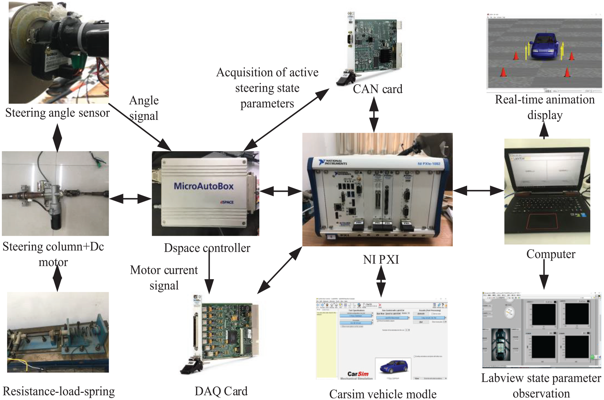
Hardware-in-loop scheme.
In the design, Carsim feeds front wheel angle, speed, yaw velocity, and so on to the controller. The controller calculates a superposition angle which is converted to the current signal and is sent to Dspace overlaid with the front wheel angle signal from Carsim. Dspace drives the motor to complete active steering. In this article, the front wheel steering resistance moment is produced by spring instead. The current of active steering motor and steering wheel angle are collected by sensors and sent to PXI. The road images and vehicle parameters can be displayed in real time. The man–road–vehicle active steering HIL test is realized.
The rotation angle of the steering string of AFS is measured by the angle sensor in real time. PXI data board card is used to simulate the real car signal environment of AFS and collect the signals. Meanwhile, the vehicle parameters are fed to the controller by the controller area network (CAN) card. Through the LabView software system in the computer, the hardware system can be controlled in real time, and the curve data can be collected and observed. Real-time data collection and transceiver interaction are carried out in NI PXI, and joint simulation of NI PXI and Carsim is used to realize vehicle environment simulation and vehicle parameters acquisition.
HIL test implementation
The PXI-based HIL test bench is built which is shown in the Figure 6 and the bench is built according to Wu et al. 31 The designed controller and relevant model and experimental actuator can be combined dynamically in real time and be easy for signal transmission. It is convenient to get the active steering controller with both performance and robustness by setting various conditions and adjusting parameters of the controller.

Hardware in the loop test bench.
In this article, the active steering control program is designed by LabView, and the output of the whole vehicle dynamics model of Carsim is used as a reference. The joint simulation control program of LabView and Carsim is compiled to PXI, and the signal transmission between the control program and the active steering actuator is carried out through the input and output interface of Dspace. The steering motor is driven to execute the control signal, and the sensor signal is fed back to realize real-time verification of the controller.
Figure 7 shows the data collected by the experimental bench. The speed of the HIL experiment is set as 120 km/h, and the road adopts DLC path. Figure 7(a) shows the lateral displacement of the test. It shows that the lateral displacement of the vehicle changes sharply and deviates from the target path seriously without control. LMI control and PID control can enable vehicles to track the path better. Furthermore, under LMI control, the path-tracking response is faster and less overshoot. Figure 7(b) is the steering wheel angle collected in this experiment. The steering column angle changes sharply without control making the vehicle lose stability. Steering column angle under PID control and LMI control can effectively achieve the steering response. Compared with PID, the steering wheel under the control of LMI responds more quickly and has a larger angle where the path curvature varies greatly, the intervention of active steering adds more turning angles to ensure the stability of the vehicle. Furthermore, it can provide a more stable steering angle compared with the model by Ji et al., 24 which gives the driver a better road feel.
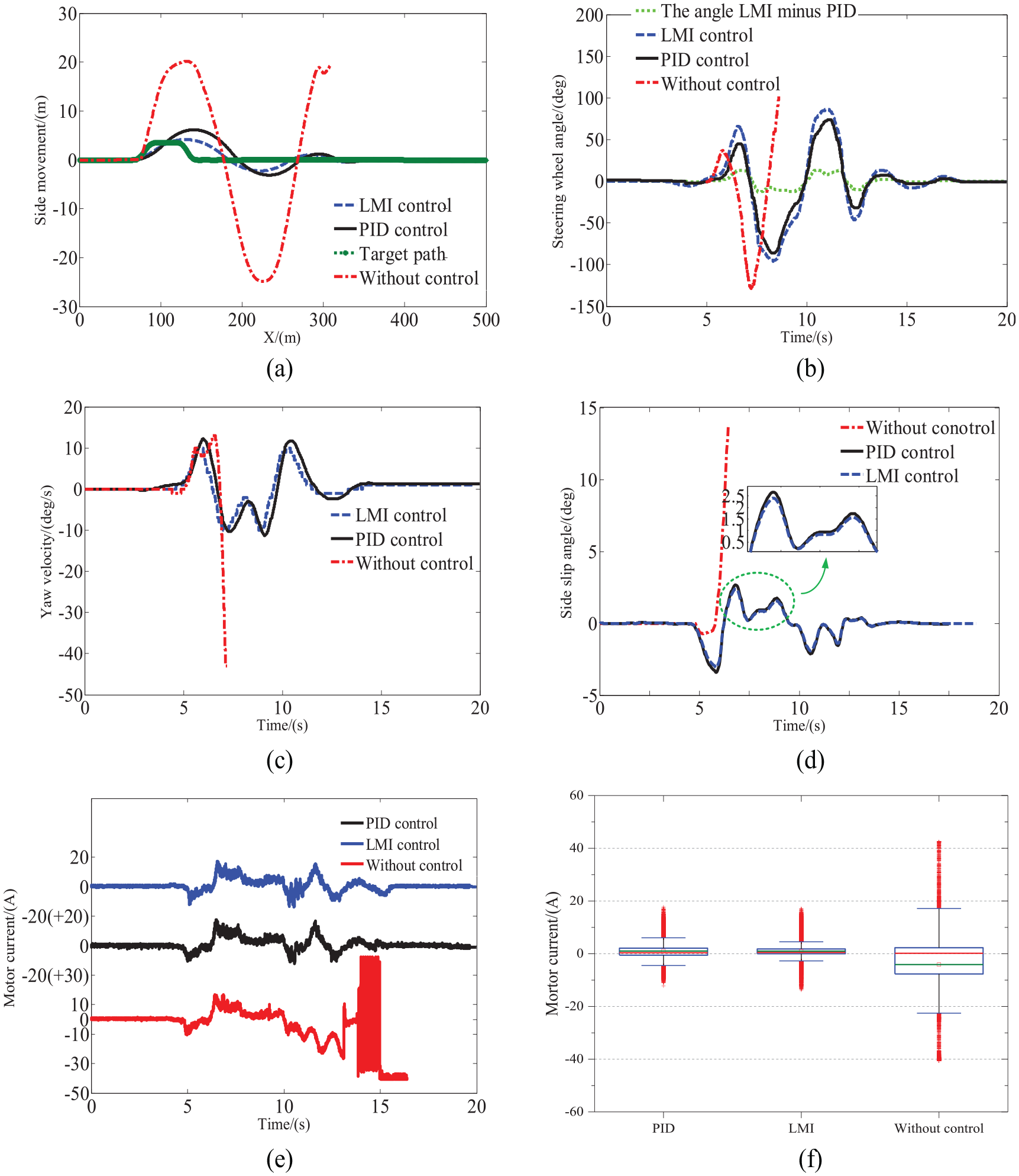
Hardware-in-loop experimental data: (a) lateral displacement, (b) steering wheel angle, (c) yaw velocity, (d) side slip angle, (e) the current of the actuating motor, and (f) box plot of the motor current for the controllers implemented on the HIL bench.
Figure 7(c) and (d) is the comparison between the yaw velocity and the side slip angle data collected by the experiment under different control conditions. As can be seen from the figure, the uncontrolled yaw velocity and the side slip angle have seriously exceeded the limit range. The yaw velocity and the side slip angle can be obviously controlled within a certain range under the PID and LMI control for active steering. However, the response speed under LMI control is faster than PID, and when the vehicle state changes sharply, the yaw velocity and the side slip angle under LMI control are both smaller, indicating that LMI active steering control can ensure better stability of the vehicle in real situation.
As AFS is mainly implemented by the steering motor, it is essential to directly observe the motor current to verify the controllers. Figure 7(e) shows the current of the executing motor collected under different control conditions in this experiment. It shows that the motor current without control starts to generate severe high-frequency oscillation in 14 s, and the current has reached the rated limit, which means that the vehicle has become unstable. In order to protect the motor, the switch relay was turned off in 16 s. Under PID control, the current can be stable within the range of plus or minus 20 A, but the motor current has certain noise fluctuations. Figure 6(f) is the box plot based on absolute value of the motor current to judge the current stability. The red points indicate the outliers, and the red line and the green line in the middle of the blue box are median and mean, respectively. The median and mean values under LMI are much closer to 0 than that with PID, which means that the motor current under LMI control has smaller noise fluctuations, and the current is more stable. The comparison shows that the LMI algorithm has better noise suppression ability.
Conclusion
In this article, the AFS controller based on LMI algorithm is designed. First, 2DOF error model is derived. Then, LMI controller based on Lyapunov equation is derived and the Lyapunov stability is verified. Both simulation and HIL implementation are carried out to validate the control effectiveness. The main work of this article mainly has the following aspects:
In the DLC scenario, LMI controller has a rapid response ability as well as PID; however, LMI controller can deal with the influence of model uncertainty and noise interference in the system to ensure better vehicle stability. HIL tests show that it can always maintain better stability in the real execution environment, and the suppression effect of current noise is better.
An HIL AFS implementation scheme is designed which can provide a very good example for the AFS long-run research and other rapid implementation of control system.
Furthermore, the influence of system friction and vehicle reversion on active steering control is not considered in the process of model building and controller derivation. The next research will be more considerate.
Footnotes
Handling Editor: James Baldwin
Declaration of conflicting interests
The author(s) declared no potential conflicts of interest with respect to the research, authorship, and/or publication of this article.
Funding
The author(s) disclosed receipt of the following financial support for the research, authorship, and/or publication of this article: This research is supported by the Research on Low-loss Harvesting Technology and Intelligent Equipment for Maize and Wheat, China (grant no. 2018CXGC0215) and the Key Research and Development Plan of Shandong Province, China (grant no. 2019GGX104047).