
Abstract
In this article, we present a systematic work to investigate the imperfection sensitivity of composite bowed-out shells with different layup patterns under axial compression. Two types of geometric imperfections, including eigenmode-shaped imperfections (produced by a first-order eigenmode imperfection approach and an N-order eigenmode imperfection approach) and dimple-shaped imperfections (produced by a single perturbation load approach and a multiple perturbation load approach), are introduced into the finite element model to predict their knock-down factors. For the eigenmode-shaped imperfections, we show that the knock-down factors predicted by the first-order eigenmode imperfection approach are riskier than the ones predicted by the N-order eigenmode imperfection approach. When adopting the single perturbation load approach, we reveal that the direction of a dimple on the shell makes a negligible effect on axial pressure bearing capacity, while the amplitude of a dimple on the shell plays a significant role in affecting the knock-down factors. Using the multiple perturbation load approach as an extension of the single perturbation load approach, we uncover that the knock-down factors predicted by the multiple perturbation load approach are more conservative than these achieved by the single perturbation load approach. In addition, we also find that the composite bowed-out shells are more sensitive to dimple-shaped imperfection than eigenmode-shaped imperfections. This work provides helpful findings for designing an airplane body and marine risers.
Introduction
Composite materials have been widely used in important loaded structures for their excellent mechanical characteristics and designability.1,2 Shell structures in the field of aeronautics and aerospace engineering primarily bear axial loads; therefore, predicting the bearing capacity of a thin-walled structure under an external load is a classic structural analysis problem. Researchers have found that the presence of an initial geometric imperfection is the main reason leading to discrepancies between experimental data and numerical results.3–6 Therefore, an initial imperfection must be considered in the early stages of structural design. Normally, the knock-down factor (KDF) is used to measure the effect of an imperfection on a buckling load, which can be determined from an imperfection sensitivity analysis.
The problem of an initial imperfection was originally proposed by Von Karman and Tsien: 7 they presented the postbuckling equilibrium path of a cylinder under axial compression. As shown in Figure 1, the buckling occurs at the limit point B, which is much lower than the bifurcation point A, where the critical buckling load of the shell is calculated by linear theory. Based on their research results, the equilibrium path of a cylinder with an initial imperfection was established.
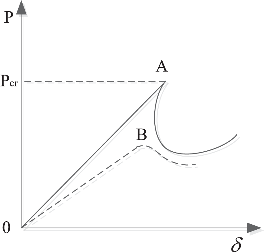
Effect of initial imperfection on the buckling strength.
The common forms of an imperfection for composite structures include geometric imperfections, delamination imperfections, and other imperfections.8,9 Scholars tend to implement an unfavorable imperfection to get more conservative results in their buckling analysis of imperfect structures. Among the different imperfections, a geometric imperfection is relatively disadvantageous to the stability of a structure. The focal point of this research is concentrated on the geometric imperfections. Realistic, worst, and stimulating geometric imperfections are the three types of geometric imperfections proposed by Winterstetter and Schmidt. 10 Realistic imperfections can be measured approximately by noncontact optical measurement methods, 11 but the key problem is that the realistic imperfection cannot be obtained and determined at the design stage and the realistic imperfection of one test case cannot simply be applied for other structures. In consideration of this feasibility in the design stage, analysis-based approaches had been developed by researchers. Worst imperfections are mathematically determined by optimization methods,12,13 but whether the imperfections provided by numerical study are close to measured imperfections is uncertain. As the assumed imperfections are based on an analysis approach, stimulating geometric imperfections come from characteristic physical buckling behavior and are similar to the experimental process. Wang et al. 14 found that the buckling load predicted by finite element (FE) analysis is very close to test results. The eigenmode-shaped imperfection approach and dimple-shaped imperfection approach are the two most common approaches to study the imperfection sensitivity of thin-walled shells. Orifici and Bisagni 15 studied the imperfection sensitivity of composite cylindrical shells using different approaches, and the results showed that stimulating imperfections do not require experimental data, and that the dimple-shaped imperfection approach can provide a clearer design load than the eigenmode-shaped imperfection approach. Wang et al. 16 studied the imperfection sensitivity of an isogrid-stiffened shell under axial compression, and they found that the dimple-shaped imperfection approach gives a close result to the test results and that the KDFs obtained by the eigenmode-shaped imperfection approach are conservative. Arbelo et al. 17 studied the imperfection sensitivity of two different composite cylindrical shells numerically with the dimple-shaped imperfection approach. He found that the multiple perturbation load approach (MPLA) gives more conservative results than the single perturbation load approach (SPLA) and is closer to the NASA SP-8007 KDF values. Pasqua et al. 18 adopted the SPLA to different conical shells, and the results showed that the KDF increases with increasing cone angle. Khakimova et al. 19 studied the composite cones with and without geometric imperfections, and the results showed that the KDFs obtained by SPLA have higher confidence than the NASA KDFs.
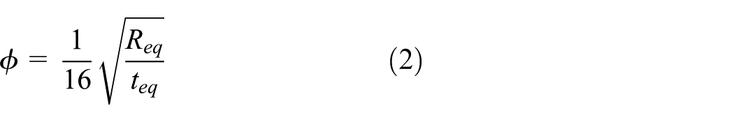
A bowed-out shell is a toroidal shell with the meridional radius of curvature as shown in Figure 2. A series of studies on the buckling behavior of metallic bowed-out shells under external loads had been carried out by Błachut and colleagues,20–24 who introduced an eigenmode-shaped imperfection to a perfect shell. The results showed that the sensitivity of different bowed-out shells to imperfection varied. Because shells with convex hyperbolic generatrix shapes are less sensitive to imperfections, Wang et al. 25 proposed a B-spline-shaped shell and made a comparison with other two designs. The results showed that the variation in imperfection amplitude has little influence on the B-spline-shaped shell. According to practical application of engineering, a bowed-out shell can be transferred to an equivalent cylinder and then designed using the NASA SP-8007 guidelines as sketched in Figure 2. The design load of a cylinder can be calculated by multiplying the linear buckling load with the KDF, where the empirical coefficient KDF “γ” can be calculated using the following formula

where
where
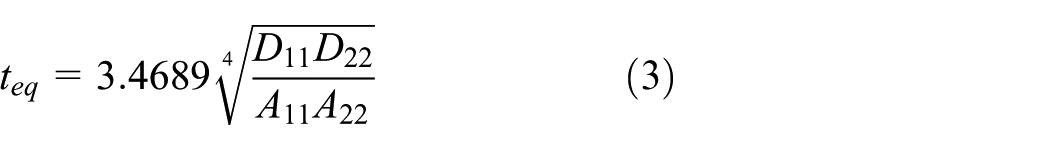
The equivalent radius of a bowed-out shell,

where R1 is the curvature radius of the arc, R2 is the radius of the bowed-out shell, H is the height of the shell, and β is the vertex angle of the arc.

Bowed-out shell converted to equivalent cylinder.
The final design load is calculated using the formula below

where
The article is structured as follows. The introduction of the eigenmode-shaped imperfection approach and dimple-shaped imperfection approach is given in section “Numerical methods of imperfection sensitivity analysis.” In section “Imperfection sensitivity analysis of composite bowed-out shell,” these approaches are used to investigate the load-carrying capacity of bowed-out shells in detail. The KDF for all cases are summarized in section “Summary of results.” We draw the conclusions in section “Results and discussion” of this article.
Numerical methods of imperfection sensitivity analysis
Eigenmode-shaped imperfection approach
First-order eigenmode imperfection approach
A loaded structure usually deforms along the first-order eigenmode because the potential energy of this mode is the minimum. According to Koiter, 5 the first-order eigenmode imperfection is usually adopted when an imperfection is uncertain. Błachut 23 found that the global structural stability is changed when a first-order eigenmode imperfection is introduced, and the buckling load of a shell is significantly affected by this type of imperfection. The first-order eigenmode shape can be initially obtained from linear buckling analysis, and then the postbuckling analysis is carried out.
N-order eigenmode imperfection approach
Although the KDFs predicted by the first-order eigenmode imperfection approach (FEIA) are usually considered to be unfavorable, the most unfavorable geometric imperfections are arbitrary. Actually, higher order eigenmodes can also be excited when structures bear an external load. Therefore, N-order eigenmode imperfection approach (NEIA) should also be performed when considering eigenmode-shaped imperfections. The NEIA is just as important as the FEIA. A sufficient number of different orders of eigenmode shapes need to be obtained to determine the worst case as accurately as possible. The expression of imperfection patterns for the NEIA is as follows

where
Dimple-shaped imperfection approach
SPLA
Hühne et al. 11 observed that the buckling process of thin-walled structures usually starts from a specific point, so they proposed the SPLA to simulate a dimple. The SPLA is very popular among researchers due to its simplicity and authenticity. A concentrated perturbation load is first applied at the surface of a shell with both ends of the shell fixed to generate a single dimple, and then an axial displacement is applied to the top end of the shell to calculate its load-carrying capacity with a nonlinear dynamic FE program. The bottom end of the shell is fixed in this loading step so the buckling load can be located from the load–displacement curve. Figure 3 shows the ideal KDF curve for SPLA. The global buckling load decreases to a constant value approximately with the increase in the single perturbation load. The threshold value, F1, is the design load in SPLA. The SPLA has been applied to cylindrical shells and conical shells successfully to perform imperfection sensitivity analyses.11,15–18 The KDF for SPLA uses the following expression

where

Sketch map of single perturbation load approach.
MPLA
As an extension study of SPLA, the MPLA was proposed by Arbelo et al. 17 The magnitude, position, and number of perturbation loads are the three parameters in MPLA. The differences between SPLA and MPLA are the number of perturbation loads. In MPLA, the perturbation loads are distributed uniformly in a circular direction located at the middle height of the shell. Therefore, the effects of the parameters of the perturbation load on the buckling loads of structures need to be further studied. Jiao and Chen 27 studied the buckling loads for cylindrical shells using MPLA, and the results showed that the distribution of perturbation loads has a significant influence on the global buckling load of a shell. Hao and colleagues28–30 also found that the number of perturbation loads has a significant influence on the buckling load when the perturbation loads are nonuniformly distributed, so they proposed the worst MPLA (WMPLA) for improving KDFs.
Imperfection sensitivity analysis of composite bowed-out shell
Model description
The geometric configuration of a bowed-out shell can be determined by four parameters as shown in Figure 4. They are

Configuration of composite bowed-out shell.
Geometries and material properties of bowed-out shell.

Validation of the simulation method
The commercial FE software ABAQUS 6.13-4 31 was used in this article. The relative results between Bisagni 32 and this article are shown in Table 2. Errors are all less than 2%, so the FE method was proved to be feasible for this case. The real observed deformation for the [0/45/–45/0] cylindrical shell in Hao et al. 29 and the present deformation echogram are shown in Figure 5. It can be seen that they match well with each other.
Error analysis of results.

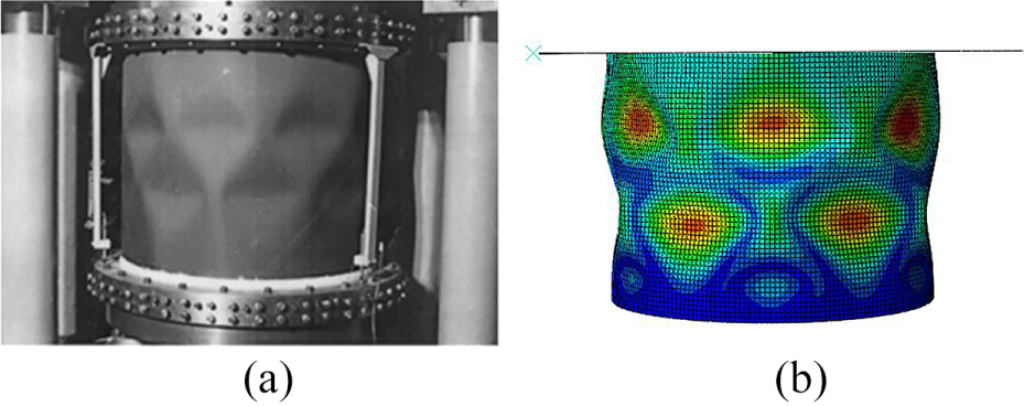
(a) The experimental buckling mode of test specimens. 32 (b) The buckling pattern obtained by FEA.
As shown in Figure 6, the finite element model is generated which can be used in mechanics analysis by setting unite type and size of the unit mesh based on the geometric model.33–35 The bottom end of the shell is constrained in all six degrees of freedom (three translations and three rotations), and the axial direction is free for the top end. Meanwhile, all nodes of the top end are linked to a reference point RP-1 by coupling constraints. An axial compression is applied to RP-1. The setting for the non-linear buckling analyses solver, ensuring effective convergence for the imperfect structures, is presented as follows:
Damping factor: 10−7;
Maximum number of increments: 105;
Minimum increment size: 10−6;
Initial increment size: 0.001;
Maximum increment size: 0.001;
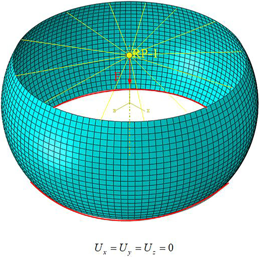
Boundary conditions and constraints of FE model.
The convergence analysis in Figure 7 shows that the buckling load decreases sharply and tends to be roughly constant with increasing element number. The buckling loads of shells obtained with 2860 elements differ only by 0.3%–1.5% from the buckling loads obtained using 4264 elements, with the computational cost being 16%–22% cheaper. Hence, 2860 S8R elements can be adopted for the model to guarantee the accuracy of the results with a reduced computational cost.

Convergence study of element size.
FEIA
The imperfection sensitivity analysis of composite bowed-out shells by FEIA is performed in this section. The first-order eigenmode shapes of each composite bowed-out shell by linear buckling analysis are shown in Figure 8. It can be seen that the layup pattern determines the eigenmode shape of the shell, and the eigenmode shape of an orthotropic shell and a quasi-isotropic shell is similar to each other. The amplitude of an imperfection, α, is defined as the ratio of the maximum amplitude of the imperfection to the total shell thickness: the range of α is [0, 1] (it is easy to be detected if the amplitude of the imperfection is bigger than the shell thickness and the product is considered to be unqualified). The results and the corresponding postbuckling deformation shapes of the cross-ply shell are shown in Figure 9. A remarkable reduction can be observed for the KDF curve of a cross-ply shell; the KDF decreases rapidly when the amplitude of an imperfection is small (0 < α < 0.3), and there is a more gradual or even negligible reduction when α is greater than 0.3. In addition, the postbuckling pattern changes with increasing α. The reductions in KDFs are relatively small for the curves of orthotropic shells and quasi-isotropic shells. The value from the curve can be assumed as the KDF when α = 1. Therefore, the KDF of an orthotropic shell, cross-ply shell, and a quasi-isotropic shell by FEIA are 0.98, 0.92, and 0.99, respectively. In this case, because of the similarity of the buckling modes, the KDF of an orthotropic shell and quasi-isotropic shell is very close to each other, which is why many researchers classify composite shells according to their buckling mode. It can be concluded that an orthotropic shell and a quasi-isotropic shell have a low imperfection sensitivity using FEIA, and of the three laminas, the cross-ply shell is the most sensitive to imperfections using FEIA.

First-order eigenmode imperfection pattern (α = 1, scaled by 10): (a) orthotropic shell, (b) cross-ply shell, and (c) quasi-isotropic shell.

Imperfection sensitivity curves by FEIA.
NEIA
The imperfection sensitivity analysis of a composite bowed-out shell using NEIA is performed in this section. The first 20-order eigenvalues and eigenmode shapes from linear buckling analysis are shown in Figure 10. The eigenvalues present a ladder form rising with each increasing order. Several representative eigenmode shapes for each cluster are chosen to generate the geometric imperfection. The imperfect FE models shown in Figure 11 are different from the corresponding models from FEIA, because the pattern by NEIA composes different order eigenmode shapes. As shown in Figure 12, the KDF of a cross-ply shell by NEIA is 0.89, which is smaller than the KDF by FEIA. The postbuckling deformation shape of a cross-ply shell also changes with increasing α, and the shapes are different from the corresponding shapes in Figure 9. The KDF of an orthotropic shell by NEIA is 0.95, and the KDF of a quasi-isotropic shell by NEIA is 0.98. Both are slightly smaller than that obtained by FEIA. This shows that the different eigenmode shapes have little effect on the sensitivity for an orthotropic shell or quasi-isotropic shell. Generally, the three composite bowed-out shells are more sensitive to imperfections using NEIA.

First 20-order eigenvalues and eigenmode shapes: (a) orthotropic shell, (b) cross-ply shell, and (c) quasi-isotropic shell.

N-order eigenmode imperfection pattern (α = 1, scaled by 10): (a) orthotropic shell, (b) cross-ply shell, and (c) quasi-isotropic shell.

Imperfection sensitivity curves by NEIA.
SPLA
The SPLA has been used widely by researchers for its simplicity, and the effects of the parameters of a perturbation load are investigated in this section.
Perturbation loads in different directions
As the shape of a dimple is uncertain, the effects of a perturbation load direction are investigated. Three typical directions for perturbation loads are diagramed in Figure 13. Take a perturbation load of 100 N as an example. The results are listed in Table 3, and aluminum as an isotropic material is added to make a comparison. This shows that when the value of a perturbation load is certain, the errors from buckling loads of a shell under different directions are quite small. This may be because the maximum amplitude of a dimple caused by different directions is the same.

Diagram of SPL with three directions: (a) along the radius direction in the XOZ plane, (b) at a 45° to the y-axis in the XOZ plane, and (c) at a 45° to the y-axis in the XOY plane.
The results predicted by SPLA with different direction of perturbation load.

PL: perturbation load.
The results for the four bowed-out shells by SPLA are shown in Figure 14. It should be noted that the global buckling load is the maximum value that a bowed-out shell can reach at the end of pre-buckling. Global buckling also means the start of postbuckling for a cylindrical shell. It can be seen that the trend of all KDF curves is the same, and these curves can be divided into a halt phase (region 1), a linear decline phase (region 2), and a plateau phase (region 3). When the perturbation load is smaller than 100 N, the buckling load is basically unchanged because the dimple is small enough to be ignored. When the perturbation load is greater than 100 N and less than 1000 N, the buckling load decreases linearly approximately with increasing perturbation load and a single dimple develops into the main factor that affects the bucking loads. When the perturbation load is greater than 1000 N, the buckling load basically tends to be a threshold value. This is because the dimple region can only bear a very small axial compression, and more axial loads will transfer to the perfect region which is not affected by the perturbation load. The KDFs of an orthotropic shell, cross-ply shell, and isotropic shell are 0.84, 0.75, and 0.79, respectively, which shows that a cross-ply bowed-out shell is more sensitive to imperfection caused by SPLA. For the aluminum shell, the turning point between the halt phase and the decline phase is postponed to 800 N, which is quite different from the other KDF curves. This is due to the amplitude of an imperfection. The relationship between the perturbation load and the imperfection amplitude is given in Figure 15. It can be seen that the discrepancy of imperfection amplitudes for different shells becomes remarkable with increasing perturbation load. For a perturbation load of 600 N, the imperfection amplitude of a cross-ply is 0.75 mm, which is about two times the imperfection amplitude of an aluminum shell. For a perturbation load of 1000 N, the maximum imperfection amplitude approximately reaches 1.2 mm, which is near the shell thickness, and the imperfection sensitivity curves are starting to reach the plateau region.

Single dimple-shaped imperfection sensitivity curve of the shell.

Perturbation load versus imperfection amplitude curve.
To reveal the mechanisms behind the phenomena of the curve from the SPLA, Figure 16 shows the relationship curves of a cross-ply bowed-out shell’s reaction load versus axial shortening as well as the corresponding deformation patterns in three phases. In Figure 16(a), the perturbation load is 100 N. Since the perturbation load in region 1 is too small to create a local snap-through in the shell, the influence of the perturbation load can be ignored, so the shell is only prone to global buckling and the buckling load is almost unchanged. The perturbation load is 700 N in Figure 16(b), and it can be seen clearly that the local snap-through occurs in the shell. In addition, the local deformation increases with increasing perturbation load, so the global buckling load decreases dramatically in the transition region 2. The perturbation load is 1500 N in Figure 16(c), and there is a local snap-through with a smooth transition and the global buckling load is almost unchanged. This is because the dimple caused by a perturbation load can lead to a local decrease in a shell’s axial stiffness. When the dimple deformation exceeds a threshold value, an imperfect region can carry little of the axial compression load, and the perfect regions which are not affected by the perturbation load carry more of the axial load. It is the area of the perfect region which mainly affects the load-carrying capacity of a bowed-out shell in this phase.

Relation curves of cross-ply bowed-out shell’s reaction load versus axial shortening as well as the corresponding deformation patterns at the three phases (a) The halt phase, PL=100N, (b) The linear decline phase, PL=700N and (c) The plateau phase, PL=1500N.
Perturbation load in different positions
As the diameter of a bowed-out shell along the axial direction is different, the effect of the axial positions of a perturbation load is discussed in detail.
Four representative positions along the axial direction are diagramed in Figure 17, and the perturbation load is perpendicular to the shell surface from the middle to the top end of the shell. The curves based on the SPLA in Figure 18 become relatively stable with increasing perturbation load, and it is evident that the KDFs show a remarkably different tendency for different positions. The KDFs for all cases are summarized in Table 4, and it can be seen that the KDF increases from the middle to the top end of the shell. The relationship between the perturbation load and the imperfection amplitude for an orthotropic shell is shown in Figure 19. The discrepancy of imperfection amplitudes for different positions becomes remarkable with increasing perturbation load. The increase in the position H4 curve is much smaller than for the other three curves, which explains why the KDF of the position H4 curve is close to 1. The position H1 provides the minimum global buckling load because the buckling deformations mainly occur near the middle of the shell.

Bowed-out shells with varying dimple positions (H1 to H4).

Imperfection sensitivity curves for different positions: (a) orthotropic shell, (b) cross-ply shell, (c) quasi-isotropic shell, and (d) aluminum shell.
KDFs of shells under different PL locations.
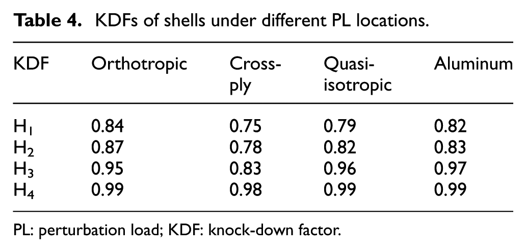
PL: perturbation load; KDF: knock-down factor.

Perturbation load versus imperfection amplitude curves for orthotropic shell.
MPLA
The MPLA is considered to be an extension of the SPLA. The MPLA is determined by three parameters: magnitude of each perturbation load, relative position between perturbation loads, and the number of perturbation loads. The effects of each perturbation load parameter in the MPLA are investigated in this section.
Relative position of the perturbation loads
The two perturbation load approach (2PLA) is chosen to study the effects of perturbation loads’ relative position in the circumferential direction. The selected conferential interval angle, θ, between the two perturbation loads is 30°, 45°, 60°, 90°, 135°, and 180°, respectively (see Figure 20). It should be noted that the perturbation loads in these cases all are located at the middle height of the shell.
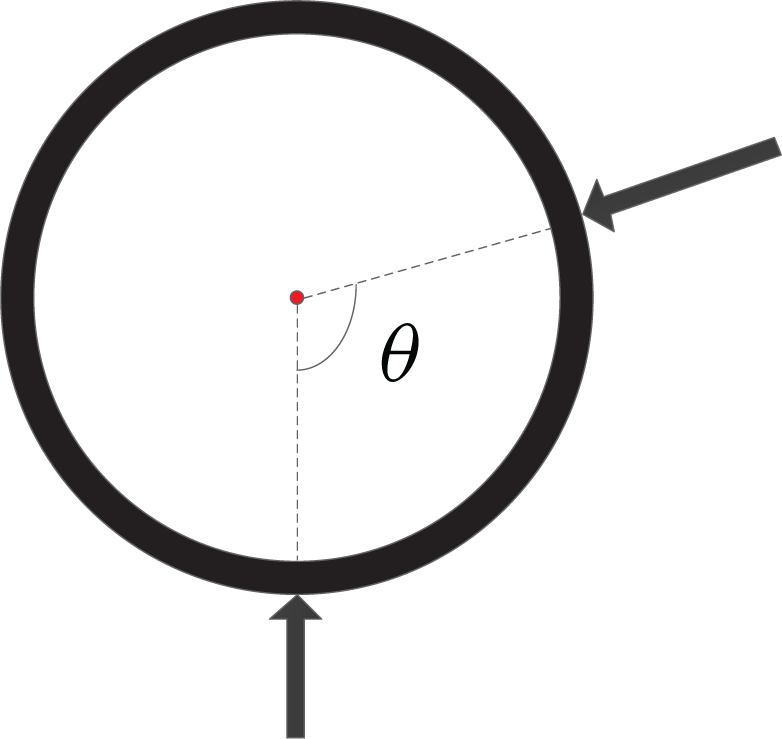
Sketch of relative position between perturbation loads.
Figure 21 shows the curves of the global buckling load of a shell versus the perturbation load under different interval angles. It can be seen that the KDF decreases as the interval angle θ increases, when keeping the number of perturbation loads unchanged. This can be attributed to the area of the imperfect region caused by the two perturbation loads. When the interval angle is relatively small, the two dimples counteract the distortions. The larger the interval angle, the larger the imperfect regions. This demonstrates that the interval angle, θ, between two adjacent perturbation loads significantly affects the global buckling load of a composite bowed-out shell.
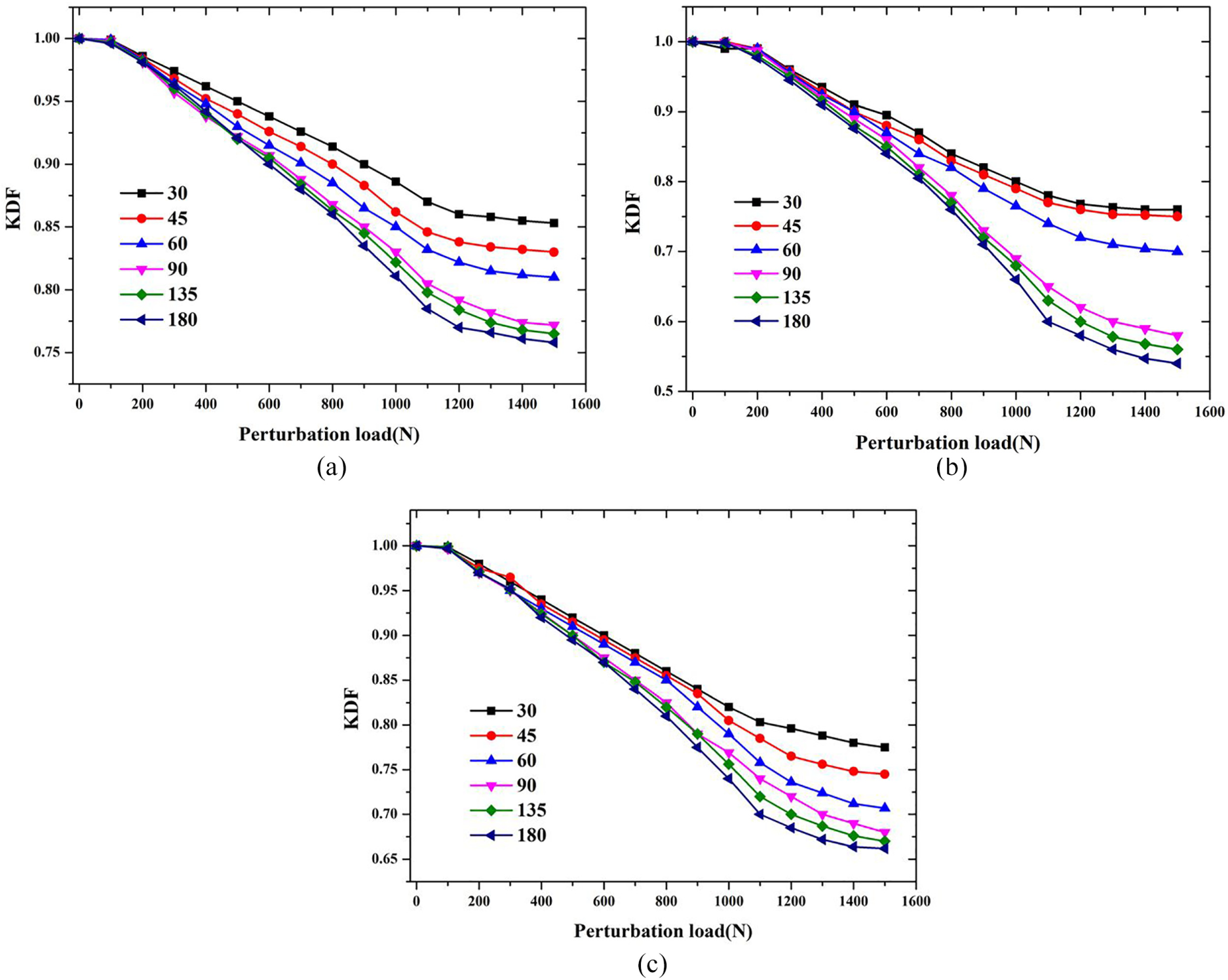
Relation curves of global buckling load versus perturbation load under different circumferential interval angles: (a) orthotropic shell, (b) cross-ply shell, and (c) quasi-isotropic shell.
Number of perturbation loads
For the purpose of investigating the effects of perturbation load number on the MPLA, four kinds of perturbation load number are selected, as shown in Figure 22, which are 3, 4, 5, and 6. In each case, all perturbation loads are evenly distributed in the circumferential direction at the middle height of the shell. The relative curves of KDF versus perturbation load under different numbers of perturbation loads are shown in Figure 23, which shows that the KDF decreases as the number of perturbation loads increases from 3 to 6. This is because of the area of the imperfect region which is caused by the increase in the perturbation load as the number of perturbation loads increases. In other words, a larger number of perturbation loads can lead to a smaller perfect shell region to carry an axial compression load, which can finally result in a lower axial load-carrying capacity of a bowed-out shell.

Four kinds of multiple perturbation load approach (MPLA).
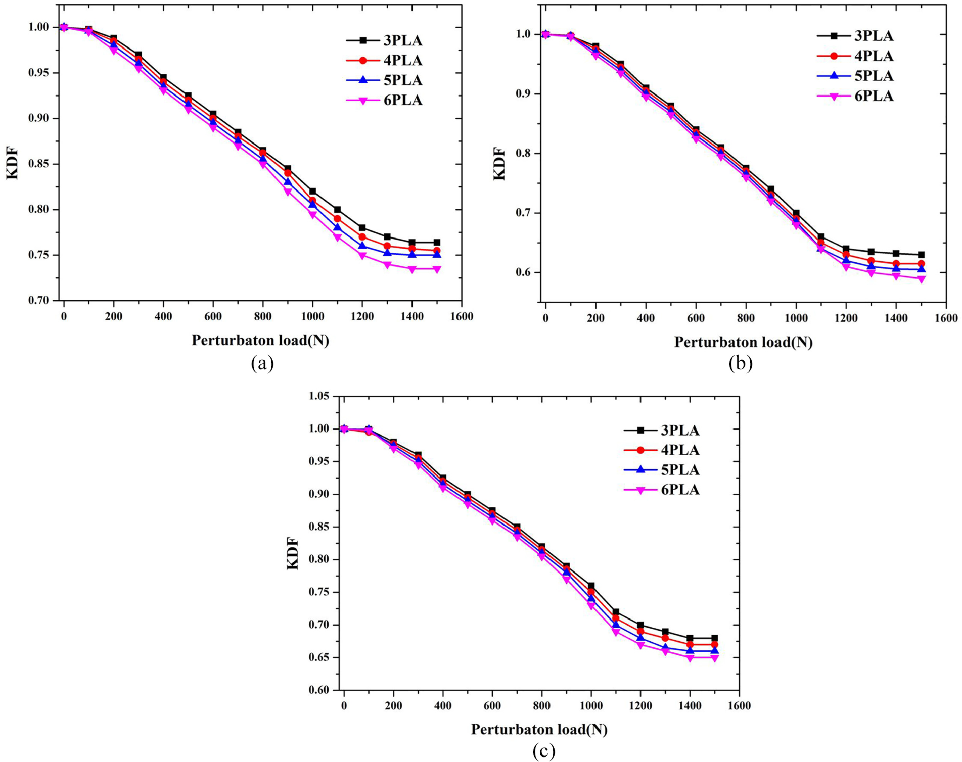
Relation curves of global buckling load versus perturbation load when perturbation loads are evenly distributed along the circumferential direction with different number: (a) orthotropic shell, (b) cross-ply shell, and (c) quasi-isotropic shell.
Summary of results
Table 5 presents the KDF for all cases. For each shell, it can be seen that the SPLA gives conservative results, but less conservative than MPLA. For an eigenmode-shaped imperfection, the N-order eigenmode imperfection gives a more conservative result. The cross-ply shell is most sensitive to the two types of geometric imperfections because the KDF is relatively small. In general, a dimple-shaped imperfection approach gives more conservative results than an eigenmode-shaped imperfection.
Summary of KDFs obtained using different approaches.

KDF: knock-down factor; FEIA: first-order eigenmode imperfection approach; NEIA: N-order eigenmode imperfection approach; SPLA: single perturbation load approach; MPLA: multiple perturbation load approach.
Results and discussion
In this article, an imperfection sensitivity analysis of composite bowed-out shell is performed. Numerical simulations are performed using different imperfection approaches. The influences of perturbation load parameters on MPLA are studied in detail. Some conclusions are achieved as follows.
For the eigenmode-shaped imperfection approach, the NEIA gives a more conservative KDF than the FEIA. In SPLA, the direction of the single dimple generally does not change the load-bearing capacity. However, the position of a single dimple along the axial direction significantly affects the global buckling loads of the bowed-out shells.
In MPLA, the interval angle between the two adjacent perturbation loads plays a dominant role in the global buckling load of a bowed-out shell. The greater the interval angle, the lower the KDF. In addition, the global buckling load decreases with increasing uniformly distributed perturbation loads along the circumferential direction, because the area of the imperfect region caused by the perturbation load mainly controls the global buckling load.
For the design of composite bowed-out shells, it should be noted that the cross-ply shell is more sensitive to geometric imperfections, and it is indeed risky to use the eigenmode-shaped imperfection approach. As an extension of SPLA, MPLA can give a safer design load, so it can be regarded as the more rational and promising design method for composite bowed-out shells.
Footnotes
Handling Editor: James Baldwin
Declaration of conflicting interests
The author(s) declared no potential conflicts of interest with respect to the research, authorship, and/or publication of this article.
Funding
The author(s) disclosed receipt of the following financial support for the research, authorship, and/or publication of this article: This work was supported by the National Natural Science Foundation of China (Grant Nos 11502210, 51709229, 51879220, 51479170, and 61803306), the National Key Research and Development Program of China (Grant No. 2016YFC0301300), the Natural Science Basic Research Plan in Shaanxi Province of China (Grant No. 2018JQ5092), and the Fundamental Research Funds for the Central Universities (Grant No. 3102019JC006).