
Abstract
The paper presents the design of a novel heat rejection system suitable for desert climates where daytime temperatures are typically high, nighttime cooling through sky radiation exchange is highly effective, and freshwater is scarce. Desert climates also feature high solar energy intensities during daytime, which can be exploited to power thermodynamic cycles. However, such cycles reject heat during operation, and daytime temperatures are too high for employing air cooling whereas scarcity of freshwater limits the applicability of evaporative cooling. We propose a system that defers dissipation of heat rejected during daytime operation to nighttime when ambient conditions are much more favorable for heat dissipation to the atmosphere. The paper presents the proposed design, its method of operation, and its implementation in a solar-driven ice-making plant in Upper Egypt. A mathematical model was developed to predict system performance and support decision-making over equipment sizing. It was used to simulate the performance of the deferred cooling system over a week. Using weather data collected at New Cairo (30.02 °N latitude, 31.5 °E longitude) in April 2017, the model demonstrated that the system could achieve a maximum temperature drop of 16 °C, which corresponds to a cooling of 47 MJ/m2/night.
Keywords
Introduction
Radiative cooling occurs when bodies on Earth emit long-wave radiation in the 8 to 13 µm infrared atmospheric window. 1 Within this window, the atmosphere is practically transparent to the emitted radiation, i.e. absorbs none of it, and radiation is transmitted straight to the sky.
Incoming infrared radiation from the atmosphere under clear sky conditions can be derived from measurements of sky irradiance and radiation spectrum or by considering the composition of gases in the atmosphere under the relevant atmospheric conditions. Radiation absorption of gases varies according to atmospheric conditions; therefore it would be necessary to take into account atmospheric conditions including temperature, pressure and density variation with altitude. Clouds can increase incoming infrared atmospheric radiation considerably because they can act as a blackbody that emits radiation near the infrared window. 1
As early as 1978, Atwater and Ball 2 created a method to compute infrared radiation fluxes and effective sky temperature. They mapped sky temperature and difference between surface and sky temperatures over the United States for different seasons of the year. Sky temperatures were lower than surface temperatures; the difference between surface and sky temperatures (referred to as the sky temperature depression 3 ) ranged between 6 and 18 °C, indicating that radiation heat exchange between terrestrial surfaces and the sky results in cooling.
Another study reported that the effectiveness of radiative cooling varies according to local climate, highlighting California as an example of a location where radiative cooling could be beneficial. 3 Thailand may also benefit from radiative cooling, as the difference between effective sky temperature and daily minimum ambient temperature has been reported to be approximately 8 °C. 1 As for Malaysia, it has been estimated that radiative cooling can reduce cooling energy requirements by up to 11%. 4 There is a need for the standardization and simplification of the methods used to select sites that would benefit from the deployment of radiative cooling. A world map showing locations where cooling needs can be met by radiative cooling is still missing. 1
Suppose that, through the use of selective materials, we could create an ideal emitter in the 8–13 µm atmospheric window and an ideal reflector outside this range, then cooling power at ambient temperature could reach up to 100 W/m2; theoretically, this could result in cooling of about 50 °C below ambient temperature if radiation energy was the sole energy affecting the perfect emitter. 5 Though such a material does not yet exist, there are ongoing efforts to create conditions that would get radiative cooling to operate as closely as possible to ideal conditions. These include using selective surfaces or screens, cover screens, paints, reflecting mirrors (for unwanted radiation outside the range) or replacement of the air between a radiator surface and the cover screen with a vacuum or another gas to suppress convection. 1
There have been a number of experimental and numerical tests of prototypes of radiative cooling systems. The majority of these prototypes were modified flat plate solar collectors used as radiators for cooling. The initial main aim was to use radiators to assist in the cooling of the roofs of buildings through sunlight reflection by day and radiative cooling by night. 1 An experiment using air as the operating fluid, a steel decking painted white and an aluminized Tedlar sheet reported a radiative cooling power in the range of 22 W/m2, with temperature reaching 6 °C below ambient temperature during the night. 6
Other systems involve circulating air from buildings into painted aluminum tubes during the night; compared with buildings without radiative precooling, these systems achieved 2.5–4 °C reduction in temperature. 7 In recent studies, air has been replaced by water as the operating fluid, because of the higher thermal capacity of water and the greater control and operation ease that water offers; these studies have tested closed and open radiator systems, with the latter having evaporation and convection cooling effects in addition to radiation. One study tested an unglazed, 2.2 by 1.3 m, flat plate type solar water heater; average cooling over 8 hours was 80 W/m2. 8 Other attempts have been made to combine heating and cooling in closed system solar collectors, achieving up to 610 W/m2 of heating and 51 W/m2 of cooling, supplying radiative cooling power of around 628 kJ/m2/night and achieving a temperature of 7 °C below ambient air temperature. 9
The need for combining thermal storage with radiative cooling was first highlighted by Ito and Miura; 10 although cooling happens at night, it is mostly needed during the day, particularly in the case of solar-powered applications. Ito and Miura were able to cool their storage tank to 2–5 °C below ambient temperature with a cooling rate of 40–60 W/m2 in summer and a rate of 60–80 W/m2 on winter nights.
In their 2017 review of research on radiative cooling, Sergi and Castell 1 noted that while research has been ongoing for several decades, research findings have not been widely analyzed. They concluded that:
wider analysis of radiative cooling phenomena is needed because, with low cooling energy densities, any small changes in the system heat flux can affect cooling behavior;
cooler temperatures can be achieved through the use of covers;
better system control is achieved when water is used as the heat carrier fluid instead of air;
higher cooling rates can be achieved through the use of heat storage.
The deferred cooling system (DCS) proposed here aims to exploit radiative cooling in desert climates to cool water that has been previously heated by the heat rejected by a condenser. Both theoretical and experimental models have been used to analyze system behavior and performance, effects of weather conditions and shield position, and other features of this novel system. The main focus of the paper is the presentation of the theoretical model and results.
Main Components of a DCS
The DCS comprises a shallow, shielded, artificial pond containing water coolant to remove heat. The water does not need to be potable; salt or brackish water works equally well. Water consumption is minimal and the water is cooled via natural cooling mechanisms prior to reuse. Three shield configurations have been adopted: upper position (shield put 1 m above the pool), lower position (shield put directly above the pool), and unshielded. The upper and lower configurations are employed during the day to block solar radiation from reaching the pool, whereas the unshielded configuration is employed after sunset to promote infrared radiation exchange with the sky. During the day, shield configuration is selected as a function of the difference between ambient temperature and water temperature. If ambient temperature is considerably lower than water temperature, then the upper configuration is selected to exploit cooling by forced convection currents from wind. If ambient temperature is considerably higher than water temperature, then the lower configuration is selected.
Figure 1 shows the shield in the lower position for the experimental rig, whereas Figure 2 shows the shield in the upper position. Because the pool needed to be removed after the experiments, we used commercial, above-the-ground, detachable, canvas-liner type swimming pools. The sides of the pool were surrounded by a reflective aluminum sheet to reflect most of the daytime incident solar radiation; ideally, these sheets should be removed at night to promote nighttime radiation exchange with the sky; however, this procedure was omitted in the experiments.
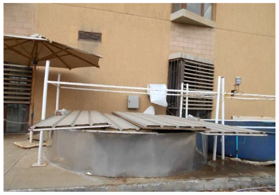
Shield in the lower position in the Deferred Cooling System.

Shield in the upper position in the Deferred Cooling System.
Natural Cooling Mechanisms
The natural cooling mechanisms of the DCS operate mainly after daylight hours; they include nighttime radiation exchange with the sky, surface evaporation, and natural or forced convection with the cool air after dark.
The effectiveness of these mechanisms depends mainly on shield position, difference between air and water surface temperatures, as well as the clearness index and relative humidity, as illustrated in Figure 3.

Heat flow for different shield positions in the Deferred Cooling System
Implementation in the Egyptian Academy of Scientific Research and Technology (ASRT) project
The ASRT funded a renewable energy research project in Shallatin. The project involved the design, assembly, and installation of a solar-driven crushed-ice production facility. Shallatin is at the southern border of Egypt, and is located along the 24 °N latitude. The site is a couple of kilometers from the shore of the Red Sea and has no access to freshwater; only highly saline brackish water is available from a local well. Analysis of water composition indicated that the well is most likely fed continuously by the sea nearby.
The objective of the project was to provide fishermen with the ice needed to preserve fish using saltwater, either from the sea or from the saline wells that were widespread in the area, without the need for electrical power from the grid. The project needed an innovative, simple, inexpensive solution to reject heat from the condenser of the ice-making plant in a remote, hot, and fairly humid area with no grid connection and no freshwater resources. 11 Photovoltaic panels with secondary battery storage were installed to provide power to the ice production plant to extend operation beyond daylight hours; 11 energy produced by the panels was mainly stored as thermal energy in the form of stored ice. 12 The ice-making system employed standard components of the vapor compression cycle that required the rejection of heat of almost 7.3 kW from the condenser. 12
A finned-tube cross-flow heat exchanger using a 300-W fan to blow air across the heat exchanger was initially considered. However, the system was finally considered to be unsuitable for the site where daytime temperatures often exceed 45 °C in summer; operating at such high temperatures, the system risks shutting off or operating at much reduced efficiency, which would affect ice production and shorten equipment lifetime. 12
A condenser using water coolant rejecting heat in alternative ways were considered. The first alternative involved circulating seawater directly through the condenser. However, this would incur considerable costs associated with the need for submersible pumps and setting up pipes over large distances overland. In addition, the prototype would only be applicable to sites close to the sea, and the system would create negative environmental impacts on marine life. Cooling towers rely on evaporation to cool the water. They consume large amounts of freshwater; they are not very effective if the site is close to the sea and has high humidity; therefore this option was also eliminated.
Thus, the DCS proposed here was adopted for this site, and the project was completed and delivered. To the best of the authors’ knowledge, it is operating without problems to this day.
Operational Procedure in ASRT project
Temperature rise across the condenser was estimated to be 5 °C with a volumetric flow rate of 0.00034 m3/ s; for 9 hours of operation per day, 11 m3 of cooling water is required each day.
Three identical ponds, each with a water storage volume of 6 m3, were built. At any moment during the operation of the system, one of the three ponds must be receiving the warm water returned from the condenser, while one of the other two would be providing the condenser with water that has been cooled the night before. At the start of the day, the receiving pond would be emptied and the other two would be filled with sufficient water to meet the day’s consumption. Diameter of the pond is 3.6 m, and the height is 0.76 m. To store 11 m3, the storage ponds need to have a minimum height of 0.522 m, which is below their actual height of 0.76 m.
At the beginning of the night, the three ponds are each filled with one-third of the daily required volume of cooling water (total daily required volume estimated as 12 m3/ day). At the end of the night, before the condenser is turned on, one of the three ponds is emptied, and the water that was in this pond is transferred into the other two with each pond receiving the same quantity of water; the empty pond is now ready to receive water from the condenser. At midday, one of the feeding ponds will become empty; a switch is then made; water from the condenser is then stored in the empty pond; the condenser is fed from the other feeding pond that has not yet been used. At the end of the day, water is redistributed between the three ponds for optimum nighttime cooling. Figure 4 shows a schematic of the procedure.

Sequence of operation of the cooling ponds.
To evaluate different scenarios in the operation of the DCS and identify scenarios that would minimize pool temperature to achieve optimum cooling, a daily lumped heat capacity, time-dependent numerical model was implemented in MATLAB. 13 The model starts by determining shield configuration (shielded/unshielded) and heating according to required time schedule (ideally sunrise to sunset) for every time interval. Then it implements the procedures for one of the following scenarios:
Unshielded scenario
This is similar to that of an outdoor swimming pool. This is the case when the pool surface is totally exposed to the sky. This would occur between sunset and sunrise as solar radiation would be absent and long-wave radiation exchange with the sky would reduce water temperature. In the desert environment, atmospheric temperature is considerably lower than pool surface temperature at nighttime; thus additional cooling can be obtained by exposing the pool surface.
Shielded scenario
The shield is placed over the pool during daytime, ideally between sunrise and sunset or during operational hours (5 am to 7 pm) for simplicity. The shield is mainly there to prevent solar radiation from reaching the pool and the associated heat gain. Daytime shield configuration is selected according to the difference between ambient and pool temperatures. There are two shield positions:
Upper shield position
The shield is placed approximately 1 m above the pool, allowing forced convection to occur between the pool surface and ambient air. The model chooses the upper position when ambient temperature is lower than pool water temperature to make use of convection currents to reduce daytime water temperature.
Lower shield position
On the contrary, the lower shield position is selected when ambient temperature is higher or marginally lower than pool water temperature. In this position, the shield acts as a wind shield, blocking forced convection currents. It is placed directly above the water, but not touching it. Being physically closer to the pool surface, it effectively prevents both beam and diffuse solar radiation from reaching the pool.
Mathematical Model
The mathematical model comprises heat balance equations for the shield and the pool. Three different scenarios were considered: the unshielded pool, upper shield position and lower shield position:
Unshielded pool
Considering pool water as a lumped heat capacity yields the following equation:
where
Calculation of the various source and sink terms is explained in a later section.
In the absence of

where
Shielded pool
A schematic of the heat balance for the combined shield and pool is shown in Figure 5.

Heat balance of shield and pool.
Heat balance of the upper surface of the shield
Heat balance of the upper surface of the shield is given by (3). Thermal inertia of the shield is omitted because of the low heat capacity of shield material.

Heat balance of the lower surface of the shield
Heat balance of the lower surface of the shield is given by (4). Thermal inertia of the shield is omitted because of the low heat capacity of shield material.

where

Radiation network for the shield in the upper position.

Radiation network for the shield in the lower position.
Heat balance of pool water
Considering pool water as a lumped heat capacity yields (5), which follows the first law of thermodynamics and equates net heat gained by pool water at any instant with the rate of change in the internal energy of the water:

where
Calculation of Heat Flows
Short-wave radiation heat gain
Gains for the unshielded pool
Heat gain from daytime solar short-wave radiation is calculated using (6). Global radiation values measured by a pyranometer on a weather station are used as inputs to the solar heat flux term (

Gains for the shielded pool
As for the unshielded scenario, global radiation values obtained from the weather station are fed into the MATLAB code. Heat gain from short-wave radiation is calculated using (7). Ideal conditions whereby the shield blocks all beam radiation and most of the diffuse radiation are assumed.

In the ideal lower shield position, the shield covers the pool completely, blocking all beam and diffuse solar radiation. During the experimental runs there is an air gap, allowing part of the ground-reflected diffuse radiation.
Long-wave radiation exchange
Unshielded pool
For the unshielded scenario, radiation losses to the sky are calculated from (8):

Effective sky temperature is calculated using (9), following Duffie and Beckman: 14
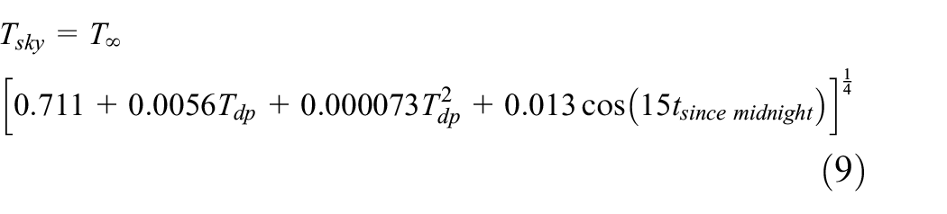
where

There is also the possibility to estimate
As in the shielded scenario, radiation losses to the sky from the upper surface of the shield facing the sky is calculated using (11):

Upper shield position
Radiation losses are calculated using the radiation networks outlined in Figure 6. Following Holman, 17 two equations are used to describe radiation exchanges between pool water, shield surface facing the pool, the ground, and the sky.
Shield and pool radiosities are calculated using (12) and (13):
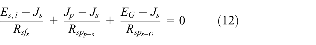

where


Ground and sky surface resistances are taken as zero as ground and sky areas are assumed to be infinite. Thus, ground radiosity (


Radiation heat flow out of the pool (


For the upper position scenario, a shape factor of 0.55 is used to calculate the space resistance
Lower shield position
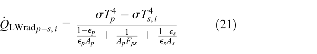
For the lower position scenario, long-wave radiation losses from the pool are calculated using (21), following the radiation network shown in Figure 7:
Convective/Evaporative heat flow
Convective/Evaporative for unshielded and upper shield position scenarios
Convective/Evaporative exchange with the environment for the unshielded scenario and for the upper position scenario is modeled using (22) and (24), respectively:

Following previous studies,18–20 heat transfer coefficient (

The heat required to evaporate the water from the pool surface is given by (24):

Following previous studies,18,21 the modified evaporation coefficient (

where

As in the shielded scenario, convective losses to the environment from the lower and upper surfaces of the shield are calculated using (28) and (30), respectively:


where
Convection/Evaporation for the lower shield position
In the ideal lower shield position, the shield is assumed to cover the pool completely, blocking all beam and diffuse solar radiation; it is assumed that condensation and evaporation effects cancel each other out during daytime, and only the effects of free convection in the enclosed space between the pool and the shield remain. Shield temperature must be below pool water temperature for free convection to occur. Following Holman, 17 free convection in an enclosed space between two parallel plates is calculated using the Rayleigh number (Ra)—product of the Grashof (Gr) and Prandtl (Pr) numbers—and the Nusselt number (Nu).
For Ra less than 1700, Nu equals 1, which means that heat is transferred by conduction only. In all other cases, Nu is calculated as a function of Ra using different coefficients as presented in (29) to (32):


where K is thermal conductivity of moist air, calculated at film temperature and X is the height of the air gap between the shield and the water surface. Free convection effect is then calculated as a function of the difference between water and shield temperature, as presented in (34):

Additional heat flow from fresh water added to the system
An additional term is added to simulate heat flow from either the addition of fresh water to the pool to compensate for evaporation or loss of mass from leakage. This term would also be used to represent field implementation of condenser cooling during the day, where hot water rejected from the condenser is added to the pool to be cooled throughout the night when the condenser is not in operation. In the MATLAB code, this term appears in the mass balance together with mass loss from evaporation or leakage and has indirect effects on heat flow.
Conduction heat flow in the shield
Conduction heat flow in the shield is calculated using (35):

where
Solution Flowcharts
The solution flowcharts for the upper and lower shield positions are shown in Figures 8 and 9.

Solution procedure for upper shield position.

Solution procedure for lower shield position.
Results and Discussion
Results of the Ideal Model
a) Simulation of DCS providing 4 hours of cooling
This section presents the results of model simulations of the DCS providing 4 hours of daily cooling using the minimum number of pools—one for holding cooling water and another for receiving hot water rejected by the condenser. Two pools represent the minimum building block for a DCS. While, in reality, more pools may be employed, for the purpose of computational analysis, this simulation scenario adopted the configuration where two pools are assumed to cool the condenser of a refrigeration machine. During daytime operational hours, the shield’s position (above the pool or flush with the pool rim) is specified on the basis of the difference between pool water temperature and ambient air temperature. The upper configuration is adopted when ambient air temperature is lower than pool temperature by at least 5 °C to make use of wind convection currents in reducing water temperature; otherwise, the lower configuration is specified. The pool is always unshielded throughout the night until 5 am in the simulations.
The pool-filling cycle for a DCS using two pools is shown in Figure 10. A simulation was conducted using weather data from April 2017. In the simulation, at the beginning of the cycle, initial pool water temperature,

As shown in Figure 10, one run takes a total of 24 hours.

Pool-filling cycle for a Deferred Cooling System using two pools.
The 4 hours during which water is withdrawn from the pool to cool the condenser form the most critical part of the cycle as the DCS tries to achieve temperatures below air temperature. For practical reasons associated with equipment selection, size, price and efficiency, water-cooled systems are more attractive than air-cooled systems for many applications, even if the water reaches temperatures that are comparable or even slightly higher than air. In the simulation, the pool receives heated water from the condenser at constant
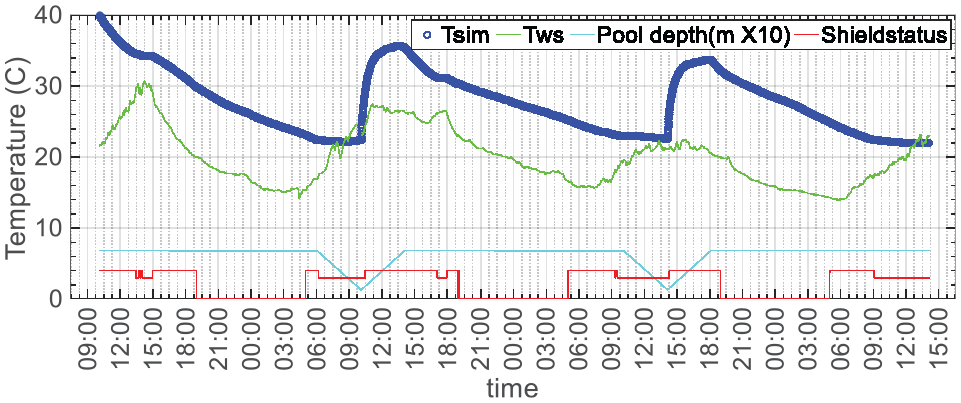
Figure 11a shows the variation of simulated water body temperature, Tsim, and ambient air temperature measured by the weather station, Tws, with time, together with water depth and shield status. Shield status is indicated by the stepped profile at the bottom of the figure; when the profile is at a value of zero, the model proceeds with the unshielded procedure; when the profile is at the maximum value, the model proceeds with the upper position procedure; when the profile is at the intermediate value, the model proceeds with the lower position procedure, with the shield resting on the pool rim.
Simulation results for the Deferred Cooling System from April 11th to 14th, 2017, with water rejected into the pool at constant
In its upper position, the shield is assumed to be large enough to block all solar beam radiation and part of the diffuse radiation. Evaporation and convection effects are accounted for as a function of measured wind speed and relative humidity. In its lower position, the shield is assumed to cover the pool completely, blocking all beam and diffuse solar radiation; it is assumed that condensation and evaporation effects cancel each other out during daytime, and only the effects of free convection in the enclosed space between the pool and the shield remain.
Using weather data from April 11th to 14th, 2017, a simulation was conducted with water rejected into the pool at constant
Figure 11c shows predicted heat losses over the simulation period. For Cairo in April, evaporative losses are the largest, followed by radiative and convective losses. The spikes in heat flows are coupled with the transient conditions that arise as the pool is filled with hot water from the condenser. When hot water first flows from the condenser into the pool, the difference between water temperature and ambient temperature is high; surface area to volume ratio of the pool water is also high. Both effects lead to high evaporative losses. Even after the pool has been filled, heat loss continues to be high during another couple of hours until water temperature and ambient temperature approach equilibrium. A sudden increase in ambient temperature is introduced in the simulation at 13:00 on April 11th; the shield changes from the upper to the lower position, suppressing convection exchange between pool water and ambient air. Figure 11c shows that, with the shield in the lower position, evaporative losses are zero, and only free convective losses remain.
Figure 12 shows simulation results for the DCS with water rejected into the pool at constant temperature
Simulation results for the Deferred Cooling System from April 11th to 14th, 2017, with water rejected into the pool at
b) Simulation of DCS providing 12 hours of cooling
In this simulation, four pools are employed; three are used to cool the condenser of a refrigeration machine and the fourth pool is a buffer. The system is expected to operate for up to 12 hours daily as a substitute for air cooling in desert climates, mostly for solar-driven equipment operating during the 12 hours of daylight. The DCS is most likely to be in operation for a maximum of 12 hours daily or for 9 hours as outlined in Figure 4 (the ASRT 9 hours operation scenario ).
Operational sequence of the DCS with four pools is outlined below and summarized in Figure 13 and Table 1. The condenser is fed with cooled water for three cycles; each cooling cycle lasts for 4 hours.
On the first day, at 6 am, the condenser starts its operation, withdrawing water that has been cooled during the previous night from pool 2 and rejecting hot water into pool 1.
At 10 am, pool 1 is full of hot water rejected by the condenser. Pool 2 is empty, and the condenser starts withdrawing water from pool 3 and rejecting water into pool 2 for the next 4 hours.
At 2 pm, pool 2 is full of hot water rejected by the condenser. Pool 3 is empty, and the condenser starts withdrawing water from pool 4 and rejecting water into pool 3 for the next 4 hours .
At 6 pm, we have three pools full of water rejected by the condenser. Filling of pools 1, 2 and 3 was completed by 10 am, 2 pm and 6 pm, respectively; cooling of all three pools continues through the night.
Right after 6 pm, water in the three pools (total volume of 3 V) is redistributed evenly across the four pools to increase the surface area to volume ratio and heat losses; thus, each pool holds a water volume of 3/4 V. A high surface area to volume ratio and a large difference between water temperature and ambient air temperature maximize heat loss rate through the night.
Before 6 am, pool 1 is emptied; the 3/4 V of water from pool 1 is redistributed across the other three pools; these three pools are now filled to the water level that they had at the start of the cycle. The operational cycle is repeated every 24 hours, starting at 6 am daily.
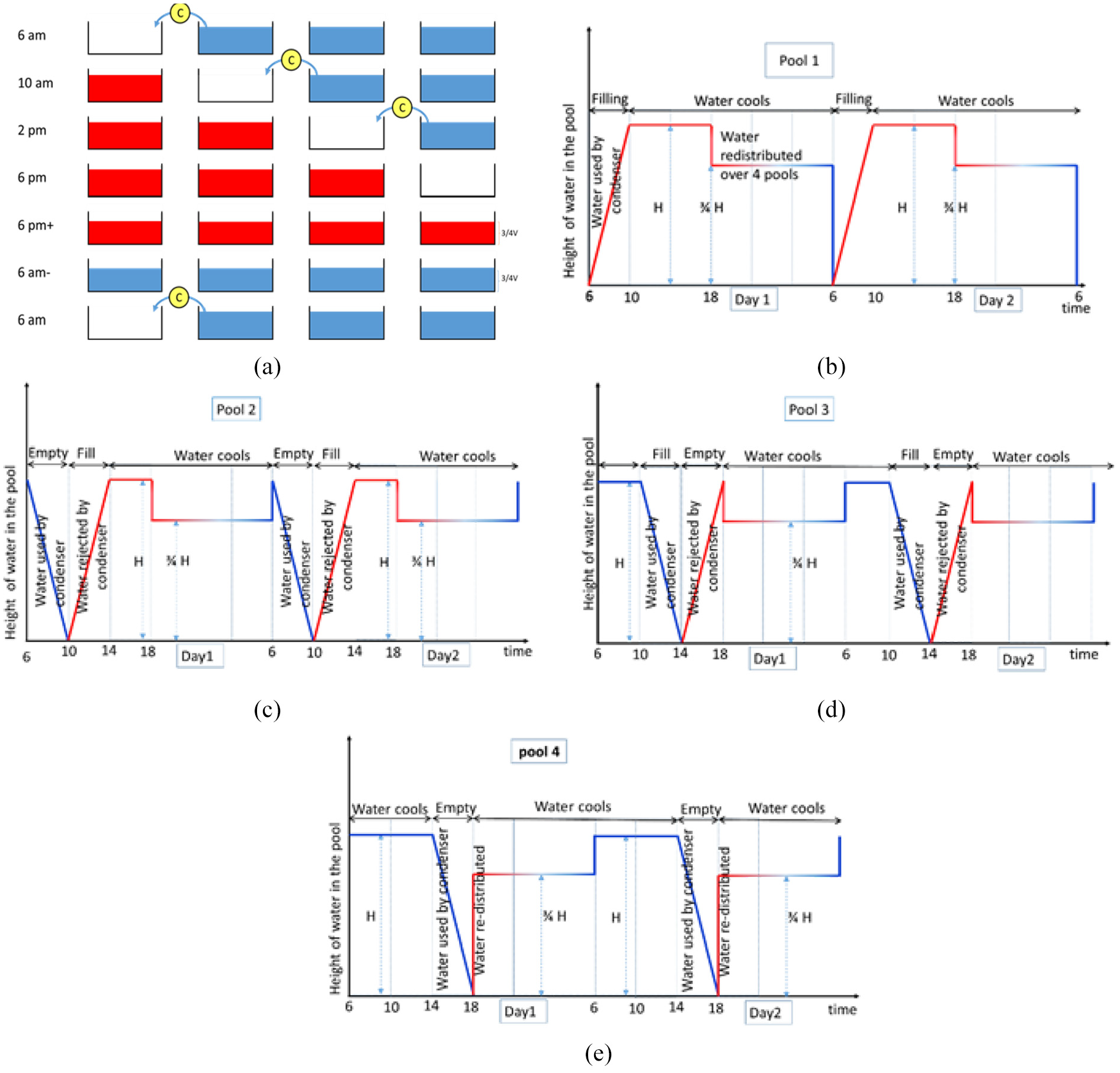
Pool-filling cycle for a Deferred Cooling System using four pools.
Cooling, emptying and filling of the Deferred Cooling System during 12 hours of operation.

While the three pools started cooling at different times during the day, cooling continues for all of them from 6 pm till 6 am the following day. From sunset to sunrise, pool water is exposed to cool nighttime skies; cooling is the most effective during this period, especially in desert climates, when long-wave radiation losses are high and cool convection currents are created by the large differences between daytime and nighttime ambient air temperatures.
The DCS has been mainly designed to replace air-cooling systems and to cool solar-driven systems operating in desert climates. Therefore, in the DCS, the condenser is not operational during the night.
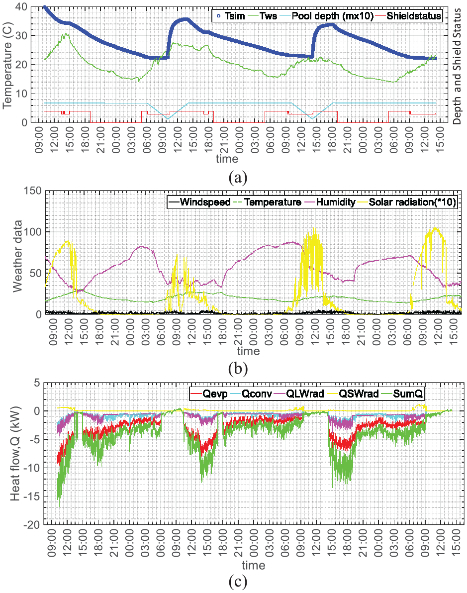
Figure 14 shows simulation results of the DCS operating with four pools to provide 12 hours of cooling using weather data from New Cairo from April 2017. It shows the variation of simulated water body temperature, Tsim, temperature of the shield surface facing the pool, TSI, and ambient temperature measured by the weather station, Ta(ws), with time, together with water depth and shield status. A maximum drop in water temperature of 16 °C is found in pool 1 on the 13th of April, which is equivalent to a cooling rate of 47 MJ/m2/night. The discontinuity in the temperature profile of pool 4 (Figure 14d) is linked with the sudden temperature increase associated with rapid redistribution of water across the pools right after 6 pm. To reflect earlier discussions about the practical implementation of the DCS, in the simulation, filling of pool 4 right after 6 pm is assumed to take only 5 minutes. In comparison, it takes 4 hours to fill one pool with hot water rejected from the condenser, and therefore a discontinuity is absent in the temperature profiles of the other pools.

Simulation results for the Deferred Cooling System with four pools using recorded weather data.
Demonstration of the DCS
Field measurements were performed (Figures 1 and 2) to demonstrate the validity of the concept of the proposed system to show the effects of the different shield scenarios on cooling and to validate model assumptions, in particular the assumption of lumped heat capacity.
Unshielded pool
Figure 15 shows simulation and experimental results for the unshielded scenario from April 19th to 26th, 2017. It shows the variation of water temperature measured at the bottom of the pool, Tbot, water temperature measured in the middle of the pool, Tmid, air temperature measured right above the pool surface, Traw, and ambient air temperature measured by the weather station Tws, with time. Variation of pool temperature as predicted by the model follows closely the trends exhibited by the measurements.

Simulation and experimental results for the Deferred Cooling System for the unshielded scenario from April 19th to 26th, 2017.
On days with high humidity when the dry-bulb temperature would be close to the wet-bulb temperature, water temperature is as high as air temperature during the day (Figure 15). However, on days with low humidity, water temperature is 10 °C below air temperature. During the day, water and ambient air temperatures both peaked at around 3 pm in the afternoon; at night, minimum air temperature was reached before sunrise while minimum water temperature was reached in the early morning hours after sunrise. Minimum and maximum water temperatures lagged behind minimum and maximum air temperatures by 2 to 3 hours, as a likely result of the large thermal inertia of water. Finally, temperatures measured at the bottom of the pool were similar to those measured in the middle of the pool, validating the assumption of lumped heat capacity.
Shielded pool
Figure 16 shows experimental results for the upper shield scenario from May 23rd to June 21st, 2017. It shows a clear time lag between minimum air temperature and minimum water temperature. Throughout the whole month, maxima in air temperatures coincided with minima in water temperatures and vice versa, confirming that pool water cooling lags behind cooling of ambient air. The upper shield position scenario is able to deliver pool temperatures below the lowest ambient air temperature at times, but deferred.

Experimental results for pool water and ambient air temperatures for the upper shield position from May 23rd to June 21st, 2017.
Summary and Conclusion
The paper presents a conceptual system for deferring the atmospheric dissipation of heat rejected from an engine or appliance operating during the day to nighttime when ambient conditions are much more favorable for heat dissipation. It is particularly suitable for desert climates where freshwater is scarce making evaporative cooling an unviable option, and where daytime atmospheric temperatures are high making air cooling impractical. Nighttime cooling by long-wave radiation exchange with the clear desert sky is particularly effective. In addition to outlining the concept of the system, the paper presents the design of a practical system that has been implemented and operating successfully in Shallatin.
The mathematical model developed in this study to predict DCS performance using on-site weather data can be employed for operation optimization, performance prediction and decision-making over equipment sizing. Using the local weather conditions at our test site, the model demonstrated the ability of the DCS to dissipate heat rejected during the day during nighttime, achieving a theoretical maximum temperature drop of 16 °C, which is equivalent to 47 MJ/m2/night.
Furthermore, field experiments show good agreement between simulation results and on-site measurements, validating the model assumption of lumped heat capacity.
Footnotes
Appendix
Acknowledgements
The authors would like to thank the Deutsche Gesellschaft für Internationale Zusammenarbeit (GIZ) GmbH Egyptian-German Private Sector Development Programme (GIZ-PSDP) and the Egyptian National Cleaner Production Center-Ministry of Trade and Industry (ENCPC-MTI) for the use of the weather station provided by them.
Handling Editor: James Baldwin
Declaration of Conflicting Interests
The authors declared no potential conflicts of interest with respect to the research, authorship, and/or publication of this article.
Funding
The authors received no financial support for the research, authorship, and/or publication of this article.