
Abstract
Under the action of strong crosswind, the aerodynamic behavior of a rail vehicle at high speed will be changed significantly, which could directly affect the safe operation of the vehicle. With the help of the shape of train used in China, the aerodynamic characteristics of trains with scale of 1:1 is investigated using computational fluid dynamics numerical simulation method, which consists of the variation of aerodynamics force and moment with wind yaw angle, wind speed, train speed, and nose shape. After an initial validation against Baker’s results from wind tunnel test, the numerical model is then used to investigate the aerodynamic characteristics of the trains. The numerical results indicate that lift coefficient of the M train is slightly higher than TMC1 and TMC2 trains. Regardless of aerodynamics force coefficients, TMC1 reaches the maximum at a yaw angle of 75°. Aerodynamics force coefficient increases with both wind speed and train speed, but the change of which is not linear. Comparing aerodynamic force with different geometric dimensions of train nose, it is shown that height–width ratio is insensitive to side force and rolling moment, but sensitive to lift force from the yaw angle 0°–90°. The side force coefficient, as we most concern, is less than other results, when the length–width ratio is 1 and height–width is 0.87.
Keywords
Introduction
With the increase of train speed, the interaction between train and air becomes very strong. Aerodynamic force generated by strong crosswind can cause derailment and overturning of trains, which would seriously affect the safety operation of high-speed trains.1–3 However, due to the complexity of air flow around trains, especially in high-speed motion, it is hard to obtain the analytical solution of aerodynamic characteristics which consists of wind pressure distribution on the train surface, wind field around the train, force and moment coefficients, and so on. In the early years, wind tunnel test and flume test were used to solve this issue.4,5 Soon, wind tunnel test were widely accepted and applied in the researches on flow characteristic around train, stability problems of train, aerodynamic configuration design, turbulence structure, and flow law.6–13 Full-scale measurement is also a valid method to investigate aerodynamic characteristic of trains but has been used in small quantities for its expensive measurement cost.14,15 With the rapid development of computer software and hardware technology, many numerical simulation methods have been used to simulate the aerodynamic characteristics of the train, especially considering crosswind effects simultaneously.16–18 Over the past decades, various parameters, which cause rail vehicle instability under strong crosswinds, have been investigated. The primary interest in these investigations was the measurement of some essential parameters such as the drag, lift, and side force coefficients together with flow behavior around train. 19 To resolve this issue, Reynolds-averaged Navier–Stokes (RANS),20–22 detached eddy simulation (DES), 23 and large eddy simulation (LES)19,24–27 have been employed to measure different parameters and investigate the flow around train subjected to side winds.28,29
RANS methods have been frequently used in the field of steady numerical simulations. It is good at predicting average aerodynamic forces acting on train subjected to a steady crosswind at a range of yaw angles. 30 Unlike RANS, LES is an instantaneous simulation method which can capture the instantaneous aerodynamic characteristics on train which is beyond the applicable range of RANS. But compared with steady methods like RANS, LES has an expensive computational cost. 31 DES, the so-called hybrid LES-RANS, is a combination of RANS and LES and can reduce resolution requirements by modeling the near-wall region. 20 The principle of DES is that the attached flow near the wall is simulated using a RANS model, whereas the detached flow is resolved using an LES model. 23
The primary aim of this research is to gain the average aerodynamic force and moment coefficient on train with different shape subjected to steady crosswind with yaw angles from 0°–90°. So in this article, we choose RANS to obtain the design quantities for its low computational cost and insufficiently mature of LES. 25 Based on the computational fluid dynamics (CFD) numerical simulation software “Fluent,” the aerodynamic force coefficients of the train in complex wind field are analyzed and the aerodynamic characteristics and parameter sensitivity of trains are investigated. By comparing the aerodynamic characteristics of the train with different length–width and height–width ratios of train nose, the optimization design on the train nose is also studied. In addition, the simulations are validated against physical experiments by Baker. 32
Model establishing and model verification
Introduction of the train and the nose shape
The entire high-speed train in this study, which is called TMC-M-TMC, consists of three vehicles. The vehicle called M is set in the middle, with two TMC vehicles connected to both side of it. TMC is a locomotive with no power, and M is the motor vehicle. The lateral views of TMC and M train are displayed in Figure 1. As shown in Figure 1, the length of the TMC trains is 24.4 m, and the M train is 22.8 m. Both widths of the TMC trains and the M train are 3 m. The top point from the ground is 3.855 m, the bottom one is about 0.8 m.

TMC-M-TMC train: (a) lateral view of TMC train and (b) lateral view of M train.
Based on the shape characteristics of Chinese locomotives, several kinds of train nose with different height–width ratios and different length–width ratios are selected. The specific details and dimensions are shown in Table 1 and Figure 2.
Dimensions of locomotive with different nose shape.


Diagram of train nose from front and lateral side: (a) front and (b) lateral.
For the sake of comparison, those models have all the following points in common:
The simulated object is an entire train with the same total length.
Necessary simplification has been made on complicated structures, which could neglect the influence of details such as wheel, pantograph, and bogie.
There is no difference among other structures, except the train nose shape.
Geometry modeling and numerical schemes
The model used in our computation is a full-scale simplified train, with totally 71.6 m in length, 3 m in width, and 2.6 m in height. The solid geometry model after meshing is shown in Figure 3. In order to facilitate the change of wind direction angle, regular 24-angular prisms with a radius of 250 and 50 m in height are established in the whole calculation domain, with the train model in the center. The model is discretized by structured grid in calculation domain, and mesh refinement is adopted around the train body with tetrahedral element. The total number of elements is 2 million, and the minimum grid space is 0.1 m.

Rail transmit train model and local mesh diagram.
The velocity-inlet boundary conditions are given on the inflow surface. The velocity, turbulence intensity, and turbulence dissipation rate are defined by exposure category B. 33 The pressure-outlet boundary conditions are used as the outflow surface. Symmetry boundary conditions are adopted at the top and sides of the calculation domain. The boundary condition of non-slip wall is adopted on the surface of the structure and ground. The realizable k-ε turbulence model is chosen as a turbulence closure model to simulate the wind flow. The velocity–pressure coupling method is SIMPLEC, and the discretization methods for the pressure and momentum equations are PRESTO and QUICK, respectively.
In addition, two kinds of mesh size were generated to study the effect of grid resolution. In order to establish a grid-independent solution, computations have been performed at a yaw angle 90° for Case 1 by two kinds of mesh sizes with approximately 2 × 10⁶ and 1.52 × 10⁶ elements. The deviations of lift force coefficients between different mesh sizes are very small, which verifies that the calculated results have nothing to do with mesh size.
Calculation method
When the train is in motion, the aerodynamic force is formed by the relative wind. Therefore, the relative wind speed should be used when calculating the aerodynamic force of the train. The relationship between train speed, inflow wind speed and relative wind speed, and definition of wind yaw angle are shown in Figure 4. 32 Due to the symmetry of the train, only seven wind yaw angles between 0° and 90° are chosen to simulate the force condition of trains. The interval of wind yaw angle is 15°, and the definition is also shown in Figure 4.

Definition of velocity vector and wind yaw angle.
The wind pressure coefficient

where
There are many different aerodynamic forces used to study aerodynamics characteristics of structures, such as lift force, drag force, side force, longitudinal moment, rolling moment, and yawing moment. As shown in Figure 5, the lift force, side force, and rolling moment are considered as three major factors to affect the stability of trains. It is very useful to analyze the effect of inflow wind, train speed, and the structure shape on aerodynamic characteristics of the train.

Sign convention for lift force, side force, and rolling moment.
The definition of lift force, side force, and rolling moment are shown as follows 34

where
Model validation
In order to validate the calculation model and method, the calculation results of a previous investigation are compared with that of Case 1 in this article (Figure 6). Based on the past wind tunnel tests, CJ Baker 32 summarized and compared the side force coefficients, lift coefficients, and rolling moment coefficients of different types of trains. The train, British Rail Derby Lightweight Diesel Multiple Unit (DMU), whose parameters are similar to the train in this study, is selected to make a comparison. It could be seen in Figure 6 that the two results have a good consistency from the wind yaw angle 0°–90°, verifying the feasibility and validity of the numerical calculation in this article.

Comparison between previous investigation and this article: (a) lift force and (b) rolling moment.
Analysis of the aerodynamic characteristics of the train
Characteristics of wind pressure distribution
Figure 7 shows the distribution of wind pressure coefficient on the surface of high-speed train at the wind yaw angles of 0°, 45°, and 90°, respectively. When

Surface pressure coefficient distribution of rail train: (a) 0° wind yaw angle, (b) 45° wind yaw angle, and (c) 90° wind yaw angle.
At the yaw angle of 45°, the front and one side of the train are facing the upwind, and the maximum value of the wind pressure coefficient is located at the juncture of the front and the side. Wind pressure coefficients at the top, bottom, and the other side of the train are negative. The maximum negative pressure coefficient value is –2.7, located at the junction of the front and the other side.
The wind pressure coefficient distribution at 90° is also symmetrical. One side of the high-speed train is facing the wind and the wind pressure coefficient is positive, while all the other surface’s wind pressure coefficients are negative. The maximum negative wind pressure coefficient is –2.9, located at the front of the train near the windward side.
Variation of aerodynamic force/moment coefficient with wind yaw angle
Figure 8 shows the variation of the side force coefficient, lift coefficient, and rolling moment coefficient with wind yaw angle. It is shown that the aerodynamic coefficient changes obviously versus wind yaw angle. Except for 90°, the side force coefficient and the rolling moment coefficient of the TMC1 train are always the largest, followed by M train, and the smallest one is TMC2 train. The side force coefficient and rolling force coefficient of the whole train are between TMC1 and M. The lift coefficient of the M train is slightly larger than that of other trains. It is indicated that the TMC1 train near the windward side is most affected by crosswind in the process of train movement, which means that the head train is at the worst disadvantage.

Variation of aerodynamic force on the train under different wind yaw angles: (a) side force coefficient, (b) lift force coefficient, and (c) rolling moment coefficient.
The three types of aerodynamic force coefficients are all 0 under wind yaw angle of 0°. The side force coefficient, lift coefficient, rolling moment coefficient of TMC1 and the lift coefficient of M train reach the maximum at wind yaw angle of 75°. The aerodynamic coefficients of other trains reach the maximum at wind yaw angle of 90°.
The simulation results reveal that the aerodynamic force of the train changes with the wind yaw angle
Fitting formula of lift force coefficient.

Fitting formula of side force coefficient.

Fitting formula of rolling moment coefficient.

Variation of aerodynamic force/moment coefficient with wind speed
Figure 9 shows the variation of lift force, side force, and rolling moment of the TMC1 train with the wind speed. The train speed is supposed to be 40 km/h, and the wind yaw angle is 90°. The results show that the lift force, side force, and rolling moment increase with wind speed, and the ratio also gradually increased. When the wind speed is 18 m/s, the three forces/moment are 13.3 kN, 15.8 kN, and 16.9 kN m, respectively. And when the wind speed is 36 m/s, the three forces are 45.1 kN, 51.3 kN, and 53.2 kN m, respectively. When the wind speed is doubled, the aerodynamic force increases by 2.39, 2.25, and 2.15 times, respectively. It is shown that there is no linear relationship between wind speed and aerodynamic force.

Variation of aerodynamic force/moment with wind speed.
Variation of aerodynamic force/moment coefficient with train speed
Figure 10 shows the variation of lift force, side force, and rolling moment of the TMC1 train (head train) with the train speed. The wind yaw angle is supposed to be 90°, and the wind speed is 18 m/s. The results show that the lift force, side force, and rolling moment increase with train speed. The relationship of the side force, rolling moment, and train speed is approximately linear, while the increasing ratio of lift force decreases slightly with the increasing train speed. When the speed is 40 km/h, the three forces are 13.3 kN, 15.8 kN, and 16.9 kN m, respectively, and when the speed is 80 km/h, the three forces are 17.0 kN, 22.1 kN, and 24.3 kN m, respectively. When the train speed is doubled, the aerodynamic force increases by 0.28, 0.40, and 0.44 times, respectively. Compared with the effect of wind speed on aerodynamic force, it can be concluded that the aerodynamic forces of the train are more sensitive to the wind speed. As a result, when the wind speed is doubled, the train speed needs to decrease more for safety purpose.

Variation of aerodynamic force with train speed.
Effect of nose shape on aerodynamic force
Influence of height–width ratio on aerodynamic force
Figure 11 shows the variation of lift force coefficients of head train, intermediate train, tail train, and whole train with different height–width ratios of the train nose. It is indicated that the lift force generally increases with wind yaw angle, and the variation of the lift force coefficient of head train, intermediate train, tail train, and whole train are similar to each other under different cases. From the wind yaw angle 0°–60°, there is no obvious gap between lift force coefficients of different cases. But from the wind yaw angle 60°–90°, which merits our particular attention, the lift force of Case 1 is smaller than that of the other cases, proving that the list force increases with height–width ratio. Lift force coefficient of Case 1 reaches the maximum at wind yaw angle of 75°, which is different from that of Cases 2 and 3 when the yaw angle is 90°.

Variation of lift force coefficient with height–width ratio: (a) head train, (b) intermediate train, (c) tail train, and
The variation of side force coefficient of head train, intermediate train, tail train, and whole train with height–width ratios of train nose are displayed in Figure 12. The side force coefficient of TMC1 increases with wind yaw angle under 75°, and reaches the maximum of 0.80, 0.77, and 0.76 in different cases, respectively. Unlike TMC1, side force coefficients of M, TMC2 and the whole train increase with wind yaw angle from 0° to 90°. Totally, there was no significant difference in the values of side force coefficients of three cases.
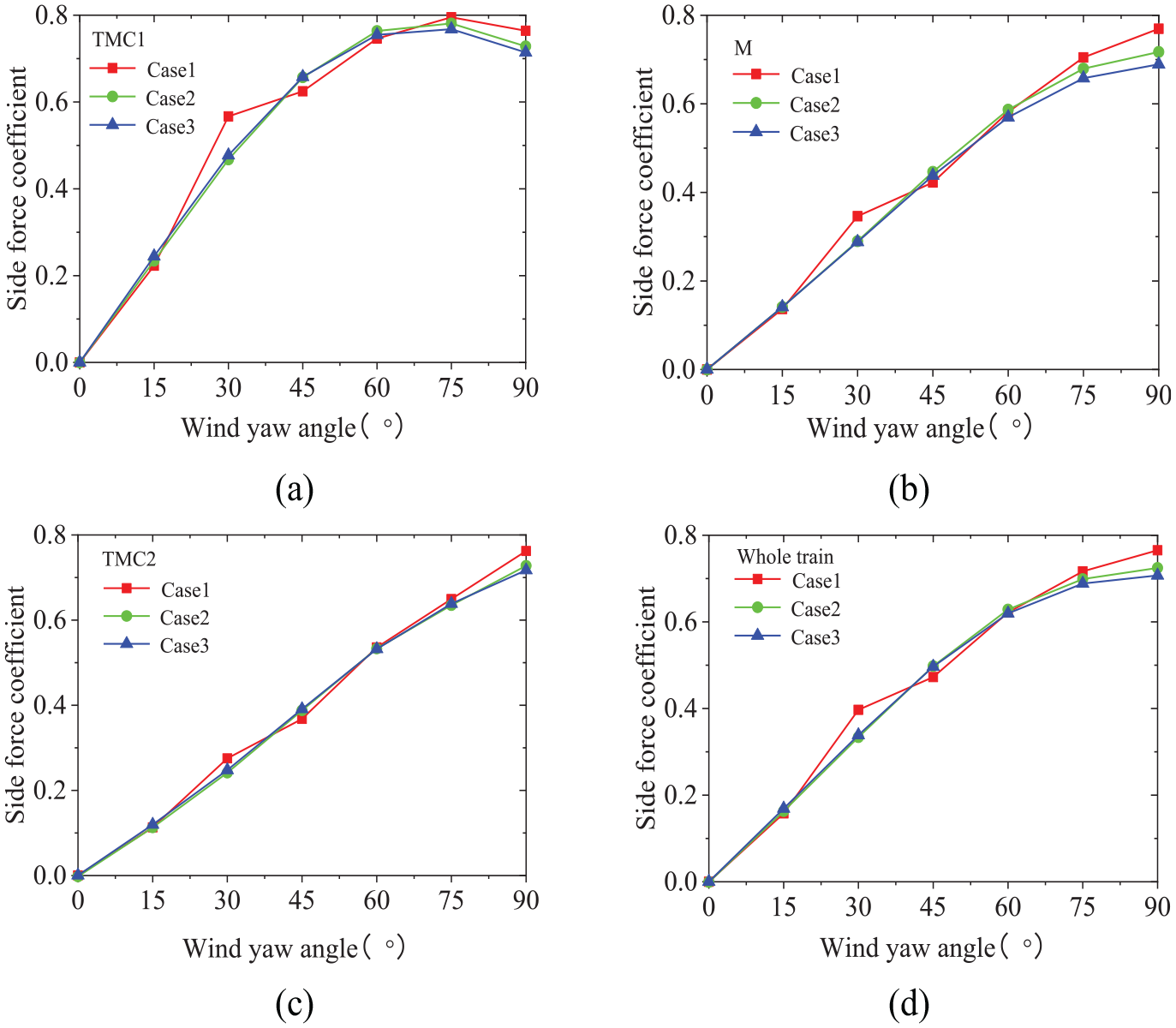
Variation of side force coefficient with height–width ratio: (a) head train, (b) intermediate train, (c) tail train, and (d) whole train.
Figure 13 shows the variation of rolling moment coefficient of head train, intermediate train, tail train, and whole train with different height–width ratios of the train nose. Like the variation of side force coefficient, the rolling moment coefficient of TMC1 increases with wind yaw angle under 75°, and reaches the maximum of 0.89, 0.87, and 0.83 in different cases, respectively. However, there was no obvious difference in the trend of rolling moment coefficients of three cases.

Variation of rolling moment coefficient with height–width ratio: (a) head train, (b) intermediate train, (c) tail train, and (d) whole train.
Influence of length–width ratio on aerodynamic force
Figure 14 shows the variation of lift force coefficient of head train, intermediate train, tail train, and whole train with different length–width ratios of the train nose. The change tendency of lift force coefficient of TMC1, M, TMC2, and whole train are almost the same as that of the two cases. From the wind yaw angle0°–45°, the lift force coefficient of Case 1 is slightly larger than that of Case 4. On the contrary, the lift force coefficient of Case 4 is larger than that of Case 1 from the wind yaw angle 60°–90°, and difference when the wind yaw angle is larger than 60°.

Variation of lift force coefficient with length–width ratio: (a) head train, (b) intermediate train, (c) tail train, and (d) whole train.
Figure 15 shows the variation of side force coefficient of head train, intermediate train, tail train, and the whole train with different length–width ratios of the train nose. There was no distinct difference in the variation of the side force coefficient of TMC1, M, TMC2, and whole train of the two cases. It is indicated that the effect of variation of train nose with length–height ratio on side force is small.

Variation of side force coefficient with length–width ratio: (a) head train, (b) intermediate train, (c) tail train, and (d) whole train.
Figure 16 shows the variation of rolling moment coefficient of head train, intermediate train, tail train, and whole train with different length–width ratios of the train nose. The rolling moment coefficient of TMC1 of Case 1 is larger than that of Case 4 with the wind yaw angle from 0° to 45°, which was opposite to wind yaw angle 60°–90°. Otherwise, there was no significant difference in the variation of M, TMC1, and whole train.

Variation of rolling moment coefficient with length–width ratio: (a) head train, (b) intermediate train, (c) tail train, and (d) whole train.
Conclusion
In this article, the aerodynamic force of the train was studied with CFD numerical simulation method, and the influence of various factors on train’s aerodynamic force was analyzed. Moreover, the effect of various train nose shapes on aerodynamics characteristic was discussed, with the reasonable train nose shape selected according to the above research. The major results could be summarized as follows:
The aerodynamic coefficient changes in evidence with the wind yaw angle. In the range of wind yaw angles, the aerodynamic coefficient of TMC1 remains the largest. It is indicated that TMC1 on the windward side is most affected by crosswind in the operation process of the train.
The lift force, side force, and rolling moment of TMC1 increase with wind speed, and the growth rate are gradually accelerated.
The aerodynamics of train increases with train speed. Within the range of the setting parameters, the relationship among side force, rolling moment, and train speed is in close agreement with a linear function, and the speed of the aerodynamic force decreases slightly with the increasing train speed. Compared with the effect of wind speed on aerodynamic force, it is concluded that the aerodynamic forces of the train are more sensitive to the wind speed.
With different height–width ratios of the train nose, the variation of the lift force coefficients of TMC1, M, TMC2 and whole train are similar. However, the lift force of Case 1 is smaller than that of other cases from the wind yaw angle 60°–90°, which proves that lift force increases with height–width ratio. Lift force coefficient of Case 1 reaches the maximum at yaw angle 75°, while Cases 2 and 3 reach the maximum at 90°. The side force coefficient and rolling moment coefficient of TMC1 increase with wind yaw angle under 75°. Unlike TMC1, side force coefficient of M, TMC2, and the whole train increase with wind yaw angle from 0° to 90°. In general, there is no significant difference in the values of side force coefficient and rolling moment coefficient coefficients in three cases.
With different length–width ratios of the train nose, the lift force coefficient of train of Case 1 is slightly larger than that of Case 4 from the wind yaw angle 0°–45°, the rolling moment coefficient of TMC1 of Case 1 is larger than that of Case 4. While from the wind yaw angle 60°–90°, the lift force coefficient of Case 4 is larger than that of Case 1, and the gap becomes more and more obvious with the increase of wind yaw angle; the rolling moment coefficient of TMC1 of Case 1 is less than that of Case 4.
Based on the comprehensive analysis of the variation of aerodynamic force coefficients of the train with different length–width ratios and height–width ratios of train nose shape, the Case 4 is optimal in this article, which meets the safety requirements of trains more easily.
Footnotes
Handling Editor: Jose Ramon Serrano
Declaration of conflicting interests
The author(s) declared no potential conflicts of interest with respect to the research, authorship, and/or publication of this article.
Funding
The author(s) disclosed receipt of the following financial support for the research, authorship, and/or publication of this article: The work described in this paper was supported by the funding of Scientific Research Fund of Institute of Engineering Mechanics, China Earthquake Administration (grant no. 2017D05), by grants from the National Natural Science Foundation of China (grant nos. 51708074 and 51908090), the Key project of Foundation and Frontier Research of Chongqing (grant nos. cstc2017jcyjAX0187 and cstc2015jcyjBX0022), the Natural Science Foundation of Chongqing, China (grant no. cstc2019jcyj-msxm0639), the Key project of Technological Innovation and Application Development in Chongqing (grant no. cstc2019jscx-gksb0188), the 111 Project of China (grant no. B18062), and the Fundamental Research Funds for the Central Universities (project no. 2019CDXYTM0032).