
Abstract
A series of stiffened panels with different dimensions and types of stiffener are simulated under longitudinal compression in finite element code ANSYS. Two bays/spans model with periodic boundary condition is adopted to consider the influence of neighbouring members. The stiffened panel adopted in the finite element mode is generally cut from the deck or bottom of a ship hull girder, and thus, the constraint on their edges depends to some extent on the relative structural response of the adjacent members. Hence, to understand the effects of constraint condition on the collapse behaviour, an extensive parametric study is carried out, employing a wide geometrical range for bulk carrier and very large crude carrier. Moreover, considering various collapse modes, the load-carrying capacities of the stiffened panels are also investigated for various stiffener types. It is found that the biaxial stress state caused by longitudinal constraint could increase or decrease the load-carrying capacity of the stiffened panel, which depends on the collapse mode and should be noticed. The transverse constraint on the longitudinal edges could cause biaxial stress state, which might increase or decrease the load-carrying capacity of the stiffened panel, which depends on the collapse modes.
Introduction
A stiffened panel is a very common structure for the deck and bottom of ship and offshore structures, which is generally designed for sustaining the longitudinal in-plane and out-plane load caused by bending moment and external water pressure or cargo weight. The experiments, numerical simulations and empirical methods had been widely used to predict the load-carrying capacity of ship and offshore structures.1,2 Xu and Guedes Soares 3 conducted a series of collapse testing of stiffened panels under in-plane compression. Using beam column and orthotropic approaches, improved expressions for elastic local plate buckling and overall panel buckling of uniaxial compressed T-stiffened panels were developed by Hughes et al. 4 Considering the load combinations of biaxial and lateral pressures, the assessment method based on the beam-column theory has been proposed for the application of requirement. 5
With the development of calculation capacity of computers, the finite element method (FEM) could capture the nonlinear characteristic of structure and is often used to simulate the collapse behaviours of stiffened panels. The FEM is a useful tool to understand the mechanics behaviour of structure, hence, which is suggested by International Association of Classification Societies (IACS)-Common Structural Rules (CSR) requirement in the advanced buckling analysis for the strength assessment of unstiffened and stiffened, hull girder and so on. 6 Based on the results in the finite element (FE) analysis, Guedes Soares and Soreide 7 studied the collapse strength of unstiffened plates and stiffened panels under various loads. Paik and Seo 8 conducted the benchmark for predicting the load-carrying capacity of unstiffened plates and stiffened panels under combined biaxial load and water pressure. Using simplified formulae and numerical simulation, Choung et al. 9 estimated the ultimate strength for three types of stiffened panels under in-plane compression and lateral pressure. It was found that the lateral pressure is more important for the stiffened panels with large column slenderness. Cho et al. 10 conducted a series of simulation for the stiffened panels under combined loads and then developed a useful formulation to assess the ultimate strength. Leheta et al.11,12 and Badran et al. 13 also adopted numerical simulation to investigate the ultimate strength of stiffened panels with tee-bar and Y-shaped stiffener.
In the numerical simulation, the geometrical range and configuration of the boundary condition should be modelled appropriately to consider the influence of adjacent member for obtaining accurate and reliable results, since the collapse behaviours of the stiffened panel include the material and geometrical nonlinearity. Based on the numerical results, the influence of boundary conditions on the transverse edges 14 and the stiffener number on the buckling strength was studied for the stiffened panel under uniaxial compression. 15 Paik et al. 16 considered the influence of torsional stiffness of supporting structures by using the governing differential equations.
In some of the research studies, the empirical formula that only includes plate slenderness and column slenderness does not considered the effect of stiffener type, that is, in Frankland.17,18 However, it was found that the collapse strength also might be different for the stiffened panel with the same sectional area, column and plate slenderness of stiffener, if their shapes of cross-section are different from the tests in Smith. 19 Hence, it is necessary to systemically investigate the influence of the stiffener type on the collapse behaviours. Moreover, the stiffened panel adopted in the FE mode is cut from the deck or bottom of a ship hull girder, and thus, the constraint on their edges depends to some extent on the relative structural response of the adjacent members. This influence relates with the stiffness of adjacent supporting members and the position of the plate. Hence, based on the numerical simulations, the effects of constraint condition on the longitudinal edges and stiffener type on the load-carrying capacity of stiffened panels are discussed in the present article.
Numerical analysis
Dimensions of stiffened panels
To obtain representative conclusions, the designed data sample used in the investigation should include various collapse modes and cover most of the dimensional range of the stiffened panels used in actual ship structures. For providing the dimensional range of ship structures, Zhang 20 had studied the range and distributions of structural member from 46 ships, which includes oil tankers and bulk carriers with length between 150 and 400 m. The statistical data indicate that the values of plate slenderness (β) and column slenderness (λ) are between 1.0 and 2.5 and between 0.05 and 1.0 as shown in Figure 1, respectively. The length (l), width (s) and thickness (tp) of the plates are in the range of 2.5–6.0 m, 0.7–1.0 m and 12–36 mm, respectively.

Dimensional distributions of the plates and stiffeners from 46 ships. 20 (a) Plate slenderness ratio. (b) Stiffener slenderness ratios.
Hence, the statistical data from both bulk carrier and very large crude carrier (VLCC) in Zhang. 20 are used to determine the geometrical characteristics of the plates and stiffeners as shown in Tables 1 and 2. The dimensions of the stiffeners and plates used in the present article had also been adopted by the International Organization for Standardization (ISO) for verification study and by Tanaka et al. 21
Geometries of plates (mm).
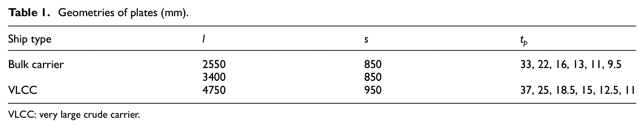
VLCC: very large crude carrier.
Geometries of stiffeners (mm).
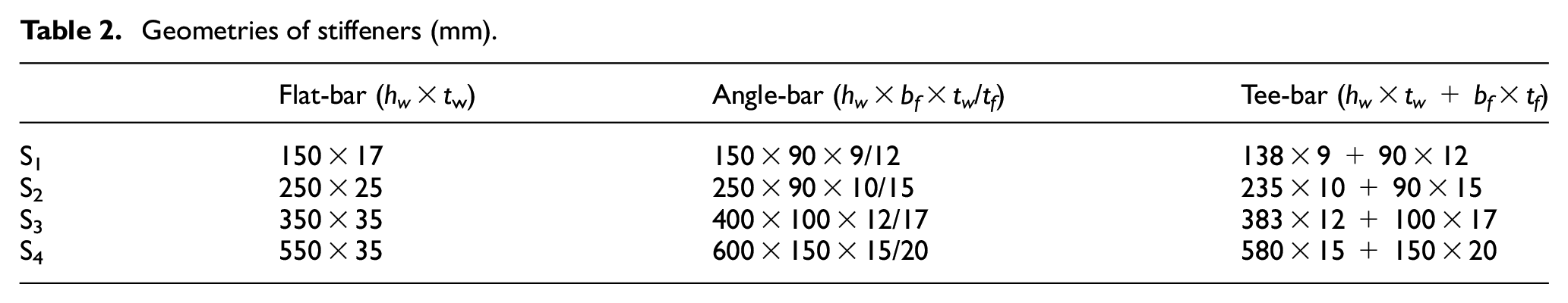
Figure 2 gives the geometries and loading of the stiffened panels to be investigated. Because of the collapse modes and characteristics of plates with different stiffener types are various, several types of stiffeners with flat-, angle- and tee-bars are considered. The cross-sections and dimensional notations of the stiffened panels are given in Figure 3 and Table 2. Six thicknesses of the plates and four sizes of the stiffeners presented as S1–S4 are considered for each type of stiffeners, which intend to cover most of dimensional combination for real ship structures.

Geometrical range and loading of stiffened panels.

Cross-sections of the stiffeners (N. A.: neutral axis).
The principle influential parameters for the load-carrying capacity of stiffened panels are given in the following 22


where I and A are the second moment of inertia and area of the stiffener including the attached plate, respectively.
FE model
The simulations of stiffened panels under compressive loads are conducted in FE package ANSYS. 23 Four-node SHELL181 elements can account for linear, large rotation and large strain nonlinear, which are used on both plate and stiffeners. The stiffened panels are made of mild steel Q345. The ideal elastic–plastic of material is adopted in the FE model, in which Poisson’s ratio and Young’s modulus and yield stress are 0.3 and 205,800 and 313.6 MPa, respectively. Figure 4 shows the geometry and FE models of the stiffened panels.

Geometry and FE models of the stiffened panels. (a) Geometry. (b) Global mesh.
Boundary conditions and loading
The boundary condition relates with not only modelling range but also collapse shapes. 14 For modelling the buckling behaviour of the local plating, it was found that the interaction between the local plate and stiffener should be included in the FE analysis. 24 Xu et al. 14 adopted the periodic condition to model the connectional influence of adjacent members, which assumes that the displacement and rotation are the same at corresponding nodal points along the boundaries. The periodical boundary configuration on the transverse edges can consider combined symmetric and asymmetric modes of imperfections and, thus, is also used in the FE simulations herein. The extended FE model with two half spans/bays (abcd in Figure 2) in both directions is employed. The overall collapse of grillage should be prevented in the design of ship structure by providing strong longitudinal girders and transverse frames, which are assumed to be rigid enough to produce lateral deflection and are not explicitly included in the FE model. Instead, the deflection of the plate and stiffeners in the lateral direction is constrained, but the rotation is set free at their locations. The configurations of boundary condition for transverse edges are given by Xu et al: 14
A1–B1: θx = θ* x , θy = θ* y , θz = 0, ux = 0, uy = u* y , uz = u* z ;
A2–B2, A3–B3: θx = 0, uz = 0;
A1–A4: θx = 0, θz = 0, uy = 0;
B1–B4:
For restrained boundary: uy = 0, θx = 0, θz = 0;
For unrestrained boundary: uy = Cdy, θx = 0, θz = 0;
A4–B4: ux = Cdx, uy = u* y , uz = u* z , θx = θ* x , θy = θ* y , θz = 0;
E2–F2, E3–F3: uy = uniform movement, θx = 0;
E1–F1 at C1, C3, C4 and C6: ux = u* x − Cdx, uy = u* y , uz = u* z , θx = θ* x , θy = θ* y , θz = θ* z ;
E4–F4 at D1, D3, D4 and D6: ux = u* x , uy = u* y , uz = u* z , θx = θ* x , θy = θ* y , θz = θ* z ;
C2–D2, C5–D5: θy = 0, uz = 0.
where ‘*’ means the same degree of freedom (DOF). Cdx is the uniform movement in the longitudinal and transverse directions, respectively, and u* x is the longitudinal movement on the stiffener top edge as shown in Figure 5.

Periodical boundary conditions for the stiffeners.
Geometrical initial imperfections
The fabrication process of structures could cause the initial geometrical imperfections, which would reduce the load-carrying capacity of the stiffened panel, and need to be included in the FE analysis. 25 According to the study in Kmiecik, 26 the equivalent initial imperfections could be assumed as Fourier components, which are given by the following.
Initial imperfection of the local plate

Column-type initial imperfection of the stiffener

Side-ways initial imperfection of the stiffener
where l and s are length and width of the plate, B is the width of girders, m is the buckling half-wave number of the local plate in the longitudinal direction; A0, B0 and C0 are the coefficient of initial imperfection, respectively.
The measured results showed that the range of coefficients of initial imperfection B0 and C0 is between 0.0006l and 0.00135l, and the maximum magnitude on the local plate (A0) is very close to 0.1.
27
Hence, the magnitudes of

The deformation updated from linear bucking simulation is generally not the same with the initial imperfections as assumed in equations (4)–(7). Hence, the values of equivalent initial imperfections calculated by equations (4)–(7) are directly imposed on the FE model by the ANSYS Parametric Design Language (APDL) in the FE code.
Convergence analysis of mesh
For assessing reliable results in the FE analysis, it is very important to perform the convergence analysis of element mesh for keeping the balance between the computation time and accuracy of results. 29 Hence, the stiffened panels with plate 2550 × 850 × 33/9.5 mm and 235 × 10 + 90 × 15 mm are used to investigate the influence of the mesh density. Six element sizes on the plate are adopted in the sensitive analysis of mesh. The ultimate strength of the stiffened panels with various element sizes is given in Figure 6. It can be seen that the collapse strength of the stiffened panels with 85- and 100-mm element size is already very close. Hence, the element size on the local plate is set as around 85 mm, and six elements are set on the flange and web of stiffeners as shown in Figure 4.

Ultimate strength of the stiffened panels with various mesh sizes.
Validation of the FE model
Six stiffened panels under in-plane compression were tested by Xu and Guedes Soares, 3 in which two (1/2 + 1 + 1/2) bays model was used as shown in Figure 7. The dimensions of the frames and the stiffeners are l 60 × 40 × 6 mm and I 30 × 8 mm, respectively. The thickness of the plate is 4 mm, and the stiffener lengths are 200, 300, 400, 450 and 600 mm, respectively. The material properties include yield stress of 483 MPa, Young’s modulus of 200 GPa and Poisson’s ratio of 0.3

Specimens and installation of the stiffened panels in the tests of Xu and Guedes Soares. 3
The experimental results are compared with those in the FE analysis, in which the unrestraint condition is adopted that is similar to that in the test. The comparison of ultimate strength between the FE analysis and tests is showed in Figure 8. The mean value and standard deviation of the ultimate strength between them are 0.944 and 0.013, respectively, which means that their results are very close. The ultimate strength of most specimens in the FE analysis is slightly larger than that in the tests. This difference could be caused by the welding residual stress and fabrication imperfection in the tests, since the residual stress is not accounted for in the simulation. The deformations of the stiffened panel are very similar in the test and numerical simulation, see Figure 9. The FE modelling technology is validated from the comparison of the results between the FE analysis and experiment.

Comparison of ultimate strength between the FE analysis and tests. 3

Deformations and equivalent stress distributions after collapse. (a) Permanent deformations in the test (FB45B2F6). 3 (b) Equivalent stress distribution of the stiffened panel.
Analysis of influential parameters
Effect of restraint condition
The adjacent member with different dimensions would give different supporting stiffness. From Figure 10, the transverse displacement on the longitudinal unloaded edges is allowed to move together for plate ‘A&C’ and is restrained for plate ‘B&D’, since the in-plane restraint conditions of the local plate might affect the collapse strength of the stiffened panel, which are different at various locations and should be considered separately.

Stiffened panels at different positions of ship structures.
If the edge is located at the end of the stiffened panel, these longitudinal edges are permitted to deform together in the in-plane direction (lower edge of local panel ‘A&C’ (see Figure 10)). Moreover, the longitudinal edges of local panel ‘B&D’ between the two adjacent local panels have a certain restraint. The rotation degrees are set free for the both cases. When the FE model with 1/2 + 1 + 1/2 spans/bays (abcd in Figure 2) is adopted, the transverse displacement at the longitudinal unloaded edges should be restrained or kept straight due to the symmetric deformation of the local plate. Hence, two types of boundary configurations on the longitudinal edges with uniform movement and restraint are adopted to investigate the influence of constraint condition.
Figure 11 compares the ultimate strength of the stiffened panels with different boundary conditions, in which

Collapse strength of the stiffened panels with different boundary conditions on the longitudinal edges. (a) Plate: 2550 × 850 mm. (b) Plate: 3400 × 850 mm. (c) Plate: 4750 × 850 mm.
The maximum value of
The value of
Mode I: overall collapse of grillage;
Mode II: collapse of local plate;
Mode III: beam-column collapse of stiffeners;
Mode IV: local buckling of stiffener web following plate collapse;
Mode V: lateral-torsional of stiffeners following plate collapse;
Mode VI: material yield of whole structure.
The failure mode of structure is significantly dependent on the geometrical combination of the plate and stiffener. Because the overall buckling of grillage is generally avoided during structural design, three collapse modes are observed as shown in Figures 12 and 13, including beam-column collapse and tripping of stiffeners and local plate. There are two buckling modes of the stiffened panel with a strong stiffener, which are plate-induced failure (Figure 12(c) and (d)) and tripping buckling of stiffener in Figure 13(c) and (d). The constraint condition on the unloaded edges enhances the load-carrying capacity of the stiffened panels having the two collapse shapes.

Collapse shapes of the stiffened panels at an ultimate limit state (plate: 4750 × 850; flat-bar stiffener: 250 × 25 mm). (a) Restraint (tp = 37 mm). (b) Unrestraint (tp = 37 mm). (c) Restraint (tp = 11 mm). (d) Unrestraint (tp = 11 mm).

Collapse shapes of the stiffened panels at an ultimate limit state (plate: 4750 × 850; flat-bar stiffener: 550 × 35 mm). (a) Restraint (tp = 37 mm). (b) Unrestraint (tp = 37 mm). (c) Restraint (tp = 11 mm). (d) Unrestraint (tp = 11 mm).
However, when the collapse mode is beam-column, see Figure 12(a) and (b), the constraint on the longitudinal edges might decrease the load-carrying capacity of the stiffened panel, with the plate slenderness ratio larger than 3. This means that the influence of the constraint on the longitudinal edges depends on the collapse shape that relates with the dimensional combination of the member. Actually, the constraint on the unloaded edges strengthens transverse tensile stress at the beginning, see Figure 14(a) and (b); with the increase of longitudinal compression, the influence of this strengthening caused by the restraint might reduce due to the unsymmetrical collapse shape (Figure 12(b)). The transverse stresses on the edge of plate (A1–A4) at an ultimate limit state are also different between them as shown in Figure 15, which illustrates that the stress states relate significantly with the collapse modes and the ratio of the length to the width of the plates. There exist several half-waves for the plate-induced collapse; for the beam-column collapse mode, the transverse stresses on the edges are compression on the outside two 1/2 spans and tension on the central one span.

Average strain and stress of the stiffened panels with various dimensions (plate: 4750 × 850 mm). (a) λ = 2.107 (S1: 150 × 17 mm). (b) λ = 0.994 (S2: 250 × 25 mm). (c) λ = 0.348 (S4: 550 × 35 mm).

Transverse stress (σx) on plate edge (A1–A4) at an ultimate limit state (plate: 4750 × 850; flat-bar stiffener: 250 × 25 mm).
The movement of the longitudinal unloaded edges might be negative or positive with the increase of in-plane compression as shown in Figure 16, in which δLongi. and δTran. are the longitudinal displacement on the transverse edge (A4–B4) and transverse displacement on the longitudinal edge (A1–A4) as shown in Figure 2, respectively. When the constraint on the edges causes transverse compressive stress, the stiffened panels are in biaxial stress state that could reduce the longitudinal ultimate strength. Otherwise, the transverse tensile stress could increase the longitudinal ultimate strength. What kind of stresses (compressive or tensile stress) would appear relates with buckling modes. From the observation of the results, the constraint on the longitudinal edges increases the load-carrying capacity of the stiffened panel having local plate collapse mode and tripping of stiffener and might decrease that of the stiffened panel with beam column collapse mode. From Figure 16, if the transverse displacement is constrained for the beam column collapse mode (e.g. β = 1.00), the transverse compressive stress caused by constraint would produce biaxial compressive stress state that could decrease the collapse strength of the stiffened panels.

Transverse displacements on longitudinal edges for unrestraint boundary condition (plate: 4750 × 850 mm). (a) S1: 150 × 17 mm. (b) S2: 250 × 25 mm.
The influence of the constraint on the longitudinal edges is dependent on the failure mode that relate with the combination of dimensions of the plates and stiffeners. This influence is slightly for the stiffened panels with a small aspect ratio and might be significantly for that with a larger aspect ratio. However, this aspect is still not considered in many empirical formulae or requirements, for example, in IACS-CSR requirement. 6 It might be needed to propose an assessment formulae of collapse strength that could consider the influence of locations of the stiffened panel, especially for specimen with a large l/s value, such as plate 4750 × 850 mm (A&B).
Influence of stiffener type
Figures 17–19 show the load-carrying capacity of the stiffened panels with different plate slenderness and stiffener types. The ultimate strength is different for the stiffened panels having various types of stiffeners; even their plate slenderness (β) and column slenderness (λ) are very close. This phenomenon also had been observed in the model tests of Smith. 19 When the plate slenderness (β) and column slenderness (λ) are the same, the ultimate strength for the stiffened panels with angle/tee-bar is very close because their flexural-torsional rigidities are very close and then, their collapse shapes are also similar for angle/tee-bar, see Figures 20 and 21.

Load-carrying capacity of the stiffened panels with different dimensions and stiffener types (plate: 2550 × 850 mm). (a) β = 1.00. (b) β = 2.07. (c) β = 3.49.

Load-carrying capacity of the stiffened panels with different dimensions and stiffener types (plate: 2550 × 850 mm). (a) β = 1.00. (b) β = 2.07. (c) β = 3.49.
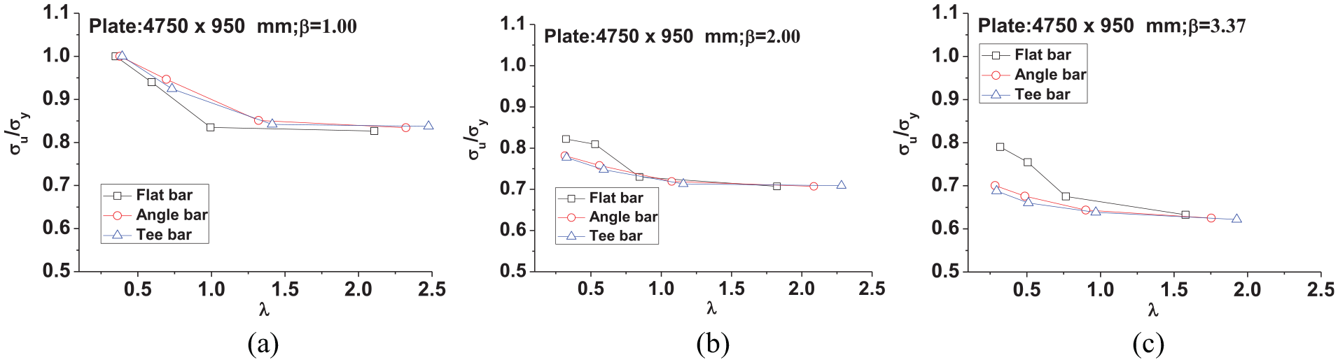
Load-carrying capacity of the stiffened panels with different dimensions and stiffener types (plate: 4750 × 950 mm). (a) β = 1.00. (b) β = 2.00. (c) β = 3.37.

Collapse shapes of the stiffened panels at an ultimate limit state (plate: 4750 × 950 × 37 mm; β = 1.00; scale: 10). (a) F1 (150 × 17 mm). (b) A1 (150 × 90 × 9/12 mm). (c) T1 (138 × 9 + 90 × 12 mm). (d) F4 (550 × 35 mm). (e) A4 (600 × 150 × 15/20 mm). (f) T4 (580 × 15 + 150 × 20 mm).

Collapse shapes of the stiffened panels at an ultimate limit state (plate: 4750 × 950 × 37 mm; β = 3.37; scale: 10). (a) F1 (150 × 17 mm). (b) A1 (150 × 90 × 9/12 mm). (c) T1 (138 × 9 + 90 × 12 mm). (d) F4 (550 × 35 mm). (e) A4 (600 × 150 × 15/20 mm). (f) T4 (580 × 15 + 150 × 20 mm).
However, the ultimate strength of the stiffened panels having the same β and λ is large between the flat-bar and angle/tee-bars, around 14%. This phenomenon should be remarked for the safety of ship during the design stage. The difference seems more obviously for the stiffened panels with a small aspect ratio, for example, plates 2550 × 850 mm and 3400 × 850 mm. When the column slenderness of the stiffened panels is small, the ultimate strength for most of the stiffened panels with flat-bar is larger than that with angle- and tee-bars, even when their plate slenderness and column slenderness are the same. With the increase of λ, the results are opposite. It can be seen that this difference relates with the collapse shapes as shown in Figures 20 and 21. However, this difference is not very pronounced for the plate 4750 × 950 mm. This means that the influence of the stiffener type on the ultimate strength of stiffened panels is dependent not only on the collapse mode but also on the aspect ratio.
For the stiffened panels with a strong stiffener, the collapse mode is plate-induced buckling, and there are several tripping half-waves on the web of flat-bar (Figures 20(d) and 21(d)); however, the collapse mode of angle/tee-bar ones is tripping buckling of stiffeners web with only one half-wave number (Figures 20(e) and (f) and 21(e) and (f)), which includes the flexural-torsional buckling. In this circumstance, the torsional rigidity is very important for this kind of tripping buckling of the stiffeners. This phenomenon was also found for stiffened laminated panels by Bisagni and Vescovini. 31 The torsional moments of inertia of stiffeners are 1.458 × 10⁻³, 1.122 × 10⁻³ and 1.028 × 10⁻³ m4 for that with flat-bar (550 × 35 mm), angle-bar (600 × 150 × 15/20 mm) and tee-bar (580 × 15 + 150 × 20 mm), respectively, which determine the side deformation and then influence the shape of tripping buckling. Hence, the collapse strengths of the flat-bar stiffened panel having larger torsional moment of inertia are larger than those with angle/tee-bar ones, even when their second moments of inertia of stiffeners are the same.
However, as the column slenderness increases, the load-carrying capacity of the stiffened panels with flat-bar decreases more quickly than that of the stiffened panels with angle/tee-bars, see Figure 17. For the stiffened panel with a weak stiffener, the stiffened panels collapse in an overall buckling mode in Figure 20(a)–(c), in which the corresponding collapses mode is beam-column failure of stiffener. For the stiffened panels with a slender plate, the collapse mode could be classified as plate-induced buckling, see Figure 21(a)–(c). The load-carrying capacity of the flat-bar stiffened panels having smaller second moment of inertia is less than that of stiffened panels with angle/tee-bar ones. This means that the ultimate strength and collapse mode significantly depend not only on the plate slenderness (λ) and column slenderness (β) but also on the flexural-torsional rigidities that relate with the type of stiffeners.
Using the regression method from numerical or experimental database, Paik and Thayamballi 32 and Zhang and Khan 33 had developed closed-form empirical formulae to assess the load-carrying capacity of stiffened panels under an in-plane compressive load, respectively, which are presented as follows.
For Paik and Thayamballi

For Zhang

for
The two expressions include only the variables of plate slenderness and column slenderness. In this circumstance, when the regression method is used to derive formula to assess the collapse strength of stiffened panels, it is better that the influential parameters of flexural-torsional rigidity should also be included in the expression to account for the tripping and torsion of the stiffener. This work will be conducted in the future study.
Conclusion
A series of FE simulations for the stiffened panels under longitudinal compression are conducted to systemically investigate the influence of boundary condition and stiffener type on the collapse strength. The transverse constraint on the longitudinal edges relates with the position of specimens, which could cause biaxial stress state that increases the load-carrying capacity of the stiffened panel for tripping buckling mode and decreases it for beam-column collapse mode. This effect is more obvious for the stiffened panels with weak stiffeners and a large aspect ratio. It is dangerous if the collapse strength was underestimated. However, this aspect is still not considered in many empirical formulae or requirements, which should be remarked and further studied for the safety of ship design.
The load-carrying capacity of the stiffened panel with the same column slenderness and plate slenderness differs for various stiffener types from the results in FE analysis. The difference between the angle- and tee-bars of stiffened panels is slightly of the ultimate strength since their flexural-torsional rigidities are close. However, the collapse strength between the flat-bar and tee/angle-bar stiffened panels is very different for some cases, even when their plate slenderness and column slenderness are the same. Hence, if the formula was regressed from the database of numerical or experimental results, it is suggested to include the torsional inertia of stiffener in the variable of expression to consider the tripping buckling of stiffener.
Footnotes
Appendix 1
Handling Editor: James Baldwin
Declaration of conflicting interests
The author(s) declared no potential conflicts of interest with respect to the research, authorship and/or publication of this article.
Funding
The author(s) disclosed receipt of the following financial support for the research, authorship and/or publication of this article: This work has been supported by the Natural Science Fund of China (Grant No. 51679100, 51609192), Fundamental Research Funds for the Central University (2018KFYYXJJ014, 2019III039) and China Scholarship Council (201706160067).