
Abstract
According to the roughing chip shape, the ultrasonic vibration cutting honeycomb material curved surface parts are divided into two rough machining processes of “V” shape cutting and rectangular cutting. Based on the non-interference characteristic cutter location counting model, the cutting efficiency model is established to select a better process. First, the residual height model of the two processes is established, and the residual height is controlled by longitudinal and lateral lifting the cutter location. Second, using the coordinate system conversion principle, the projection method is used to perform global interference check on the triangular-blade and the disk-blade which are used for ultrasonic cutting honeycomb composite, and then the characteristic cutter location generation method for changing the swing angle to avoid interference is proposed. Finally, a cutting efficiency model is established. Process analysis of case parts shows: when the feed rate of disk-blade is less 0.6 times to that of triangular-blade, the machining efficiency of “V” shape cutting is higher than that of rectangular cutting. When the disk-blade’s feed rate approaches or exceeds the triangular-blade’s, especially under this circumstance that the large parts is cut, the efficiency of the latter is higher.
Keywords
Introduction
After several decades of development, honeycomb composites have became an indispensable material in the aerospace industry since the first successful trial of it in the 1940s. 1 Honeycomb composites have superior physical properties such as high specific strength, high specific stiffness, high temperature resistance, and flame retardancy. They are usually used as sandwiches to support the aerospace aircraft’s wings, floors, engine shields, and other components. 2 However, traditional milling processing problems have appeared because of the orthotropic and heterogeneous structural characteristics of honeycomb materials, such as low processing efficiency, poor processing quality, and serious dust pollution. 3 The introduction of ultrasonic CNC cutting technology has solved the above problems well. However, there is no mature theoretical support in the research of ultrasonic vibration cutting honeycomb materials processing technology, and lack of efficient tool path planning method, resulting in low processing efficiency and economy. The tool path planning of high-efficiency ultrasonic vibration cutting of honeycomb materials is of great significance to improve the production efficiency of honeycomb core parts and to promote the application of ultrasonic processing technology in the field of aerospace weak stiffness material processing.
Domestic and foreign scholars have matured the interference inspection of common tools such as ball-end milling cutters, flat-bottom milling cutters, and conical milling cutters commonly used in five-axis machining. Y Cai et al. 4 proposed a method to obtain the interference amount by solving the minimum distance from the surface to the tool. W Li et al. 5 narrowed the data range by determining the effective active area of the tool pose, so as to quickly determine whether the interference is based on the position of the point on the surface in the tool coordinate system. Can and Ünüvar 6 proposed a method to avoid interference by keeping the distance from the points on the curve between adjacent paths to the tangent plane equal. The abovementioned interference inspection methods are all for rotary cutters, but the triangular-blade of ultrasonic vibration cutting are non-rotating cutters that are symmetric to the neutral surface, and the interference judgment between the cutter and the surface of the component is special. Zhang and Ge 7 established an energy consumption assessment model based on material removal rate for machine energy efficiency problems and proposed a new process path optimization scheme. Kong et al. 8 compared several CNC milling tool path machining schemes through two process analysis software and pointed out that the tool path has an impact on machine tool energy consumption. In the field of traditional CNC machining, the machining efficiency is defined as the material removal rate per unit time. 9 Most researchers in the field of cutting efficiency 10 optimize cutting path by optimizing process parameters such as interval and depth.
Based on the analysis of the two rough machining tool path schemes of “V” shape cutting and rectangular cutting, this article proposes to use the maximum axial cutting depth of the finishing tool (the disk-blade), that is, the maximum allowable residual height of the roughing processing as the constraint. The roughing path planning model of the residual height is controlled by two methods: longitudinal lifting and lateral offset. Using the space coordinate system conversion principle, the transformation from the workpiece coordinate system to the tool coordinate system is established. Through the projection method to judge the different interference of the triangular-blade and the disk-blade in the cutting process, the interference avoidance strategy is proposed, and the parameters such as the swing angle and coordinates of each characteristic knife position are determined. Then, the characteristic cutter location counting model of path planning is established by combining parameters such as step size, depth of cut, size of parts and blank. Finally, the processing time is regarded as the evaluation criterion of processing efficiency, and the cutting efficiency models of two roughing schemes are established. Based on the process parameters of the domestically produced ultrasonic vibration cutting honeycomb materials numerical control equipment and the constraints of the same disk-blade finishing allowance (Rough residual height), we analyze the influence of feed rate and part scale on the processing time of the two processes.
Part structure and processing technology
Ultrasonic vibration cutting characteristics of honeycomb core parts
In the aerospace industry, the processing surface of a honeycomb core part as a supporting part of a wing, an aircraft floor, a spoiler, and so on, is generally a curved surface having a small curvature and a gentle change. 11 The surfaces of most of the parts can be expressed as a three-dimensional surface formed by a two-dimensional curve sweeping along the normal direction of the plane in which it is located. Typical parts are shown in Figure 1. The two-dimensional curve is expressed by the Bezier curve formula as follows

where

Typical honeycomb core parts.
The shape of the blank in the initial stage of forming the honeycomb core material part is a rectangular parallelepiped material. From the block blank shape to the final part shape can be divided into two processing stages: the first stage is to remove a large amount of machining allowance to form a preliminary surface close to the curved shape, which can be called the roughing stage; the second stage is the finishing stage of removing a small amount of residual material from the surface to form the final parts surfaces.
The honeycomb materials ultrasonic vibration cutting equipment is equipped with two special tools: the triangular-blade and the disk-blade. The cutting motion of different types of tools is quite different, as shown in Figure 2. The main motion of the disk-blade is similar to that of a conventional milling cutter and has a rotational speed n and a feed velocity Vd, and additionally adds longitudinal vibration of the ultrasonic frequency along the axial direction. The triangular-blade includes the feed velocity Vt along the cutting direction and the ultrasonic vibration along the axial direction during cutting. The ultrasonic vibration system is sensitive to the cutting force load, and the excessive cutting force load may cause the ultrasonic vibration system to malfunction. According to the previous theoretical research11,12 and actual machining conditions, the process parameters such as the feed rate Vd, the cutting edge length d, the rake angle α, and the tool inclination angle θ are the main factors affecting the cutting force. The main process parameters affecting the ultrasonic vibration cutting of the disk-blade include the feed rate Vd, the axial depth of cut ap, and the radial depth of cut f.
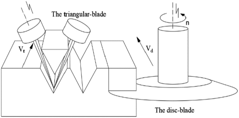
Ultrasonic vibration cutting tool.
Comparison of two ultrasonic cutting processes
In the roughing stage of honeycomb core parts forming, most of the remaining amount on the blank should be removed. In the finishing stage, the disk-blade is used to remove a small amount of machining allowance to complete the final forming; therefore, a large proportion of the processing time for the entire part forming is the roughing stage.
At present, there are two rough machining methods commonly used in ultrasonic cutting of honeycomb core parts: The first type is a single triangular-blade that cuts the material by swinging the tool plane. The shape of the slit that produces the chip is a “V” shape, and the machining process is called machining processes of “V” shape cutting. The second type is a combined combination of a disk-blade and a triangular-blade. The formed chip has a rectangular cross section and the process is called machining processes of rectangular cutting.
The machining processes of “V” shape cutting:
In Figure 3, in the same cutting layer, the triangular-blade performs the first pass cutting with a certain swing angle α, depth of cut ap, and step f. After one layer traverses the cutting, keep the cutting dept and step distance unchanged, change the swing angle to –α and cut again in the same layer, and make two cuts to form the “V” strip-shaped chips in the Y direction (tool feeding direction), where
Schematic diagram of the machining processes of “V” shape cutting.
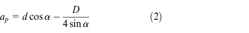
As shown in Figure 3, since the triangular-blade must be kept a distance from the remaining part material when cutting, the triangular-blade thickness D is less than 2 mm, so the distance e = 1 mm is taken. At this time,
The step size must satisfy the formula (3) to achieve chip dropping of each cutting layer and collision-free cutting of the tool

2. The machining processes of rectangular cutting:
In Figure 4, the triangular-blade performs the first pass cutting with a swing angle α = 0° and a certain depth of cut ap = d and step f. Then, using the disk-blade for the second cutting, observed from the XOZ plane, rectangular strip-shaped chips are formed along the tool feeding direction.

Schematic diagram of the machining processes of rectangular cutting.
The advantage of the machining processes of “V” shape cutting is that only one tool is required for the entire roughing cutting process, and the auxiliary time for tool replacement can be saved compared with the process of cutting rectangular chips by two tools. However, there is a swing angle in the plane of the cutter in “V” shape cutting, and when the cutting length is d, the depth of cut ap is smaller than that of the machining processes of rectangular cutting. In addition, in order to ensure smooth chip breaking, it is necessary to strictly control the lamination depth, otherwise when the material is deformed, it may result in unsuitable blanking.
The advantage of the machining processes of rectangular cutting is that the triangular-blade cuts at a 0° swing angle, the cutting force is reduced, and the ap can be appropriately deepened. However, the depth of cut is also subject to the axial cutting depth of the disk-blade, and this process has two knives combined processing; each cutting layer needs a tool change, affecting the processing efficiency.
Establishing a characteristic cutter location counting model
The number of characteristic cutter location N refers to the representative tool position located in the XOZ plane (the cutter location appearing later refer to the characteristic cutter location), which is one of the important factors determining the processing efficiency. Establishing the correct characteristic cutter location counting model is the basis for establishing two cutting process’s cutting efficiency models.
Establishing residual height model
In order to establish a characteristic cutter location counting model with high efficiency and qualified rough machining surface, the residual height must be smaller than the axial cutting depth of the finishing tool disk-blade. It can be seen from Figures 3 and 4 that the residual shape of the rough processing of the two processing processes is quite different, so the residual height model is also different.
The residual height model for the machining processes of rectangular cutting is

Among them, the value of d is limited by the cutting depth limit of the triangular-blade and the limit value of the axial depth of the disk-blade; f is determined by the radial cutting depth limit of the disk-blade.
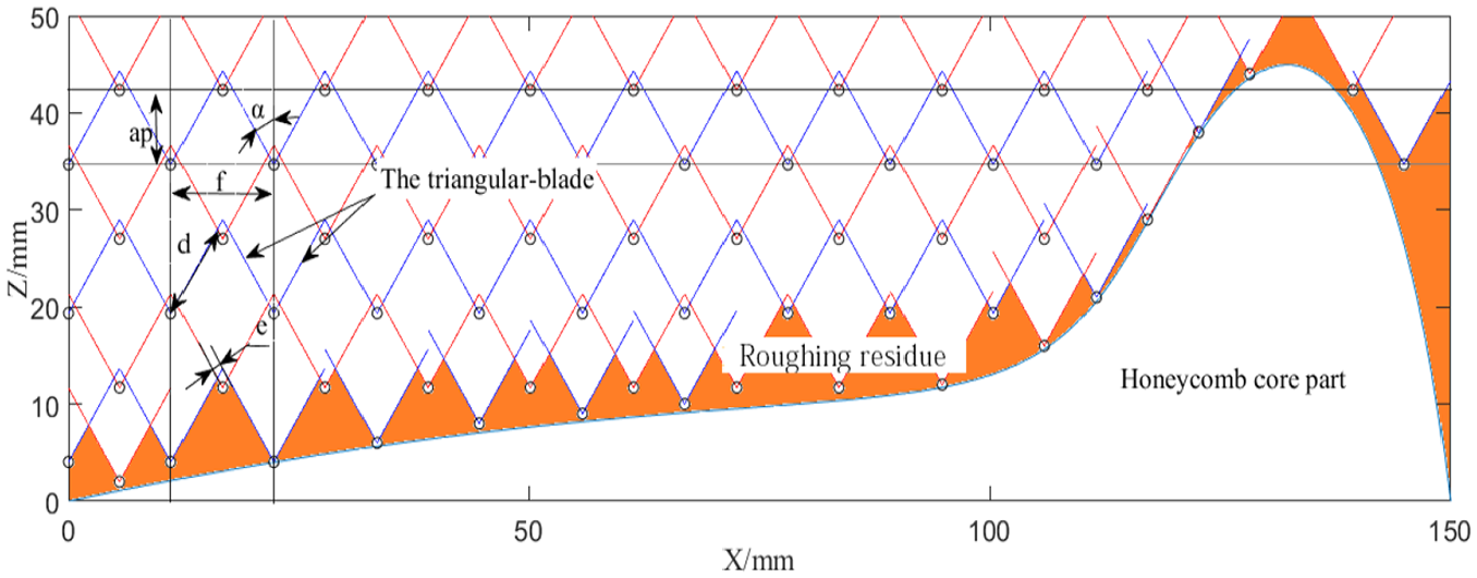
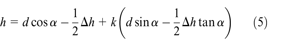
2. Figure 5 shows the geometric relationship of the residual height of the machining processes of “V” shape cutting. In the figure,

Schematic diagram of the residual height of the machining processes of “V” shape cutting.
The residual height obtained by formula (5) is inversely proportional to Δh. When the cutter location is located on the cutting layer (Δh = 0), the residual height is the largest, which is

Residual height control strategy
When the cutter location is arranged, the cutter location is located below the cutting layer, that is, the material side position. If you discard this point, it may cause the roughing residual height to be too large; if you keep this point, it will lead to overcutting. Therefore, the residual height is controlled by longitudinal lift or lateral offset and selective retention.
The machining processes of rectangular cutting If finishing and roughing use the same size disk-blade: At this time, the residual height limit hmax coincides with the axial depth of cut limit dmax of the disk-blade in roughing, so the Z-direction residual height h ≤ d ≤ dmax = hmax. That is, the residual height of the Z direction in the workpiece coordinate system does not exceed the limit residual height, and it is only necessary to consider whether the X-direction residual height of the workpiece will exceed hmax. Pre-retain the cutter location on the inner surface of the parts closest to the surface. If the X value of the tool point plus the step distance f can be placed outside the surface of the parts, the cutter location is retained. If the disk-blade used in finishing is smaller than that used in roughing: As shown in Figure 6, at this time dmax > hmax. When the formula (7) is satisfied, the adjacent cutter location

where z(t) represents the z-coordinate of the intersection of the z direction of the point P1 and the surface of the part. hmax represents the maximum residual height that the finished disk cutter can withstand.

Schematic diagram of the residual height of the machining processes of rectangular cutting.
2. The machining processes of “V” shape cutting
It can be seen from the formula (6) that the limit value of the residual height is related to the triangular-blade’s cutting in feed depth d and the swing angle α. In the calculation program of the number of cutter locations, it is judged according to formula (8): When this formula is satisfied, the residual height does not meet the requirements. The cutter location P1 can be lifted in the longitudinal direction to avoid the residual height being too large, and the lifting height is Δh; when this formula is not satisfied, the cutter location is not required to be lifted

When simulating a “V” type tool path, if the part slope is large, the cutter location closest to the part surface will appear vacancy of the cutter location in upper layer of this point. This causes the straight knife to cut too much depth when cutting the lower layer and then leads to poor surface quality or even broken knife. By adopting the method of laterally lifting the cutter location, this situation can be effectively avoided. Therefore, the method of combining the lateral and vertical combined lifting cutter locations is finally selected to avoid the problem of excessive residual height.
Tool interference checking
The interference between tool and material in NC machining is mainly divided into curvature interference, knife bottom interference, and global interference. Curvature interference and knife bottom interference occur in the cutting edge, and global interference occurs in the tool bar. The geometric difference between the ultrasonic tool and the traditional milling cutter is mainly in the cutting edge, so the interference form is also different from the traditional milling cutter; the cutter bar portion is similar to the conventional cutter and requires global interference checking.
In this article, the projection method is used to judge whether the ultrasonic tool has global interference with the curved surface.
13
First, a three-dimensional coordinate system transformation is performed. As shown in Figure 7, the point P(x, y, z) to be detected in the workpiece coordinate system W is converted into the tool coordinate system T by the coordinate system transformation formula (9), and get the point

Schematic diagram of workpiece coordinate system and tool coordinate system

where


Judging interference of the disk-blade interference
Shown in Figure 8 is the disk-blade projection diagram. If the cutting edge and the tool bar satisfy the formulas (10) and (11), interference will occur. The interference judgment expression is as follows


Schematic diagram of projection of the point to be measured in the disk-blade.
2. Judging the interference of the triangular-blade
Due to the difference in geometry between the triangular-blade and the disk-blade, the disk-blade is a revolving body, and the triangular-blade is only a symmetrical body, so there will be differences in the interference judgment expression. As shown in Figure 9, the cutting edge thickness D1 of the triangular-blade generally does not exceed 2 mm, and the margin for roughing is generally set to 3 mm, which does not overcut in the tool thickness range. Therefore, it is not necessary to judge whether the point P′ to be measured is in the blade in the H1 segment. The cutting edge part is idealized as a thin line, and it is only necessary to judge whether the H1 segment has an intersection with z-axis of the tool coordinate system. The interference judgment expression of the triangular-blade is:
Cutting edge
Tool bar


Schematic diagram of projection of the point to be measured in the triangular-blade.
When machining a five-axis CNC machine tool, the method of avoiding global interference of the tool is generally a lifting knife and a swinging cutter shaft. When the residual height is too large, the lifting operation has been completed. This operation avoids excessive residual height and avoids interference in some cases.
Since the curvature of the honeycomb-like curved parts is small, the triangular-blade swing angle is 30 degrees during the cutting process (the larger the swing angle, the larger the tool load), and the disk-blade is 3 to 5 degrees. Usually both blades are tilted more than the surface of the part. If the tool still interferes with the curved surface after the knife is lifted, the swing angle can be directly adjusted to 0 degrees to avoid interference, and the tool load is small at this time, so the tool force can be ignored when the tool swing angle is adjusted to 0 degree.
Calculate the number of characteristic cutter locations
The number N of cutter locations is determined by factors such as the size of the blank, the shape of the curved surface of the honeycomb core parts, the cutting length d of the triangular-blade, the swing angle α, and the step distance f. The specific point calculation is determined by the following algorithm:
Step 1. Inputting the characteristic curve formula of the surface parts and enter the blank size.
Step 2. Setting cycles for cutting parameters such as d, α, h in the machining processes of “V” shape cutting and d, f in the machining processes of rectangular cutting.
Step 3. Calculating the number of layers imax, the maximum number of cutter locations per layer gmax

The machining processes of rectangular cutting

The machining processes of “V” shape cutting

When i is an even number and the machining direction is the positive x-axis direction

where xm, zm are the blank dimensions and zmin is the lowest point of the parts surface in the z direction.
Step 4. Parameter initialization. N = 0, i = 0, g = 0.
Step 5. Recording the cutter locations coordinates, angle parameters, and number, and keep the cutter locations above the curve. The cutter locations below the curve is lifted or discarded according to the residual height control strategy.
Process route comparison
The development of modern industry and the growing demand for economic benefits are increasingly demanding processing efficiency. Establishing a cutting efficiency model, based on which a reasonable processing technology is selected, is of great significance for improving production efficiency.
Establishing cutting efficiency model with processing time as evaluation index
Material removal rate per unit time can be used as the evaluation index of the cutting efficiency of CNC machining. For ultrasonic assisted cutting of honeycomb materials, whether or not finishing with a disk-blade after roughing depends on the residual height of the surface of the parts. Regardless of the cutting process used for roughing, as long as the maximum residual height left for the finishing is consistent, the overall cutting efficiency of the parts depends on the machining time of the roughing.
According to the literature, 14 the machining time mainly includes the machine tool standby time tst, the cutting time tcut, the tool change time tct, and the air cutting time tair. However, when comparing the cutting efficiency between the machining processes of “V” shape cutting and the machining processes of rectangular cutting, the machine tool standby time and the air cutting time are basically the same, so only the cutting time tcut and the tool change time tct need to be considered. Therefore, the processing time objective function as:
The machining processes of “V” shape cutting

The machining processes of rectangular cutting

The cutting time formula is

According to the process parameters such as blank size, cutting depth, and step distance of the processed honeycomb material, the non-linear regression formula containing the undetermined coefficient of the machining processes of “V” shape cutting and rectangular cutting is preliminarily introduced. This formula is universally applied to any Bezier curve

The cutting depth and drawing pace determine the number of chips, which is the denominator in the first term of the two formulas. (Formula (20) has been simplified.)
A preliminary cutting efficiency model is obtained by combining (19)

Establishing a cutting efficiency model based on the case
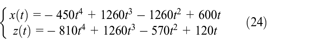
According to the calculation process of the number of characteristic cutter locations in previous section, two cutting processes are used for the parts that the same random two-dimensional curve is swept to form the curved surface. Change the different process parameters, and control the residual height to be less than the same limit of 10 mm. After the algorithm is realized by MATLAB, the calculated values of the tool points as shown in Tables 1 and 2 can be obtained. According to formula (1), the Bezier curve equation of the sample as
Statistics of the number of tool points and cutting parameters of the machining processes of “V” shape cutting.
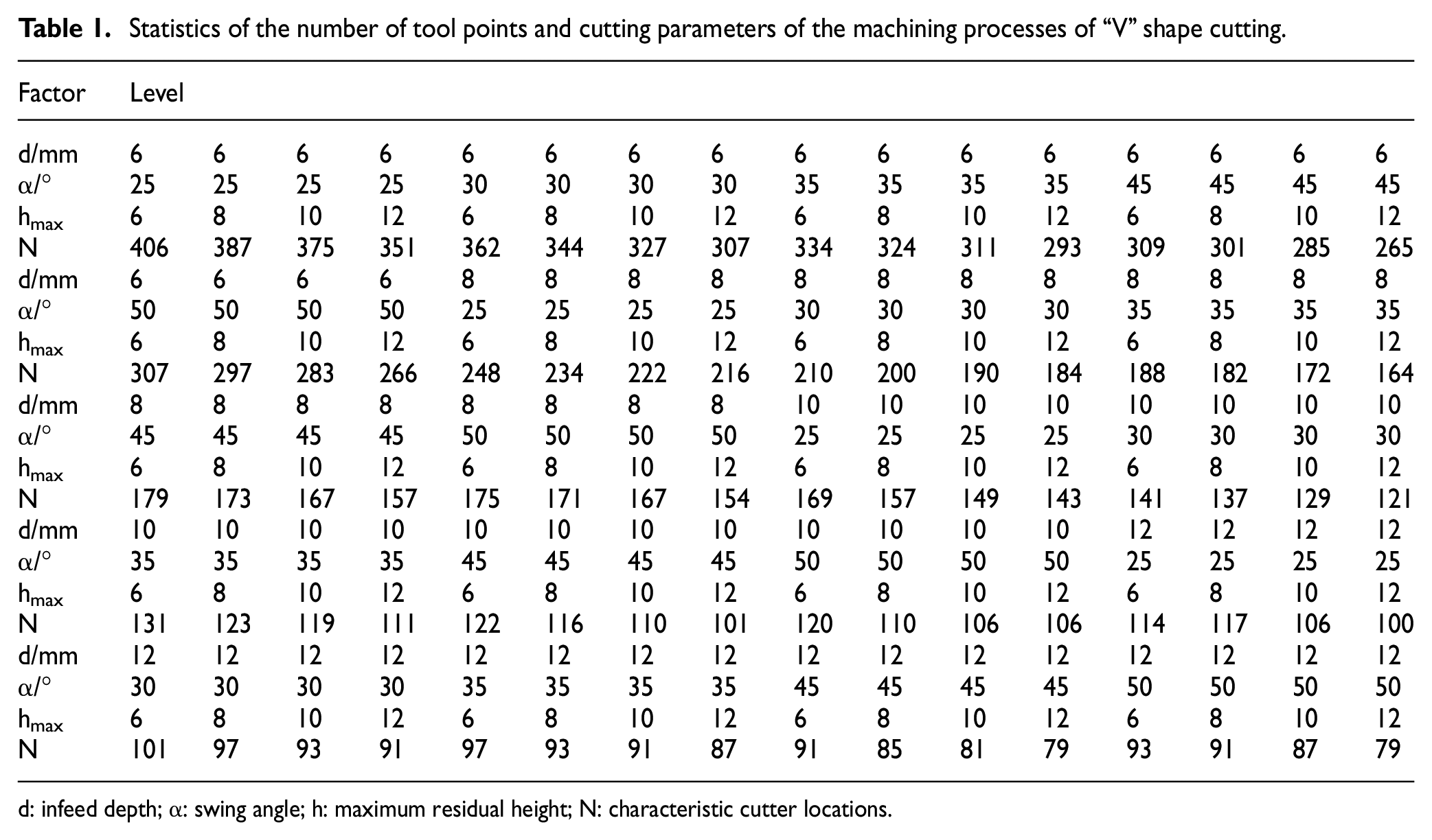
d: infeed depth; α: swing angle; h: maximum residual height; N: characteristic cutter locations.
Statistics of the number of tool points and cutting parameters of the machining processes of rectangular cutting.
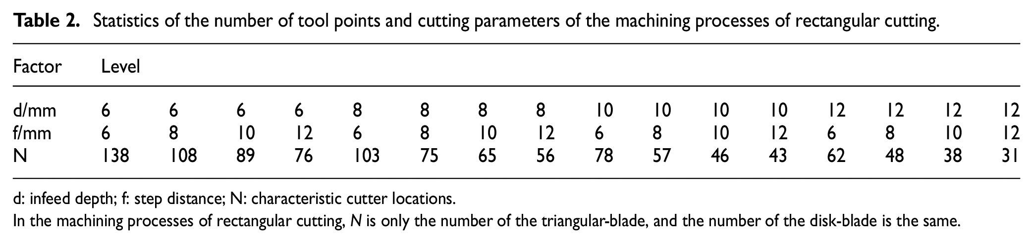
d: infeed depth; f: step distance; N: characteristic cutter locations.
In the machining processes of rectangular cutting, N is only the number of the triangular-blade, and the number of the disk-blade is the same.
Taking N as the dependent variable, the parameters α, d, and f are independent variables, and based on the sample data, multivariate non-linear regression analysis is performed with of SPSS software. The iterative records are shown in Table 3 and Table 4. It can be seen from the table that the optimal solution has been found after 4 iterations and stops running.
Iteration history of the machining processes of “V” shape cutting.

Iteration history of the machining processes of rectangular cutting.

According to the iterative result of Table 3, the coefficient of determination

According to the iterative result of Table 4, the coefficient of determination

The cutting efficiency model can be obtained by combining the characteristic cutter location counting model
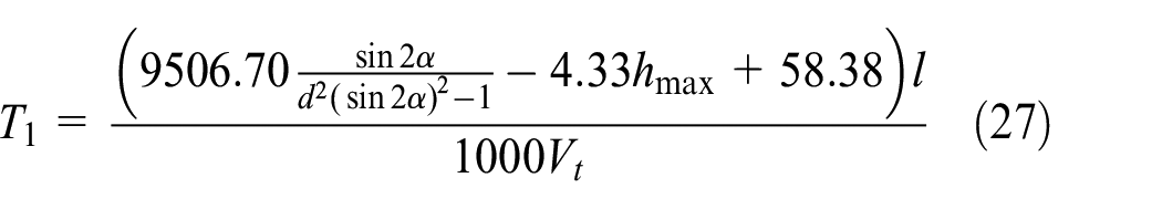

In the formula, T is the cutting time, l is the thickness of the honeycomb core part in the Y-axis direction, and V is the tool feed rate.
Considering the actual production and processing, the disk-blade’s feed rate is less than the triangular-blade’s feed rate. Generally, the feed rate of the disk-blade is in the range of 3 to 6 m/min, and the feed rate of the triangular-blade is in the range of 5 to 10 m/min. The feed rate of the disk-blade is 0.3 times, 0.6 times and equal to the triangular-blade. The remaining process parameters are the limit values of the current ultrasonic cutter. According to the above model, MATLAB is used to draw the three-dimensional fitting map that the dependent variable is T and the independent variables are l and V. The results are shown in Figures 10–12.

Change of cutting time when Vd = 0.3Vt.

Change of cutting time when Vd = 0.6Vt.

Change of cutting time when Vd = Vt.
From Figures 10–12, you can get:
It can be seen from Figures 10 and 11 that when Vd < 0.6Vt, the cutting efficiency of the machining processes of rectangular cutting is always lower than the machining processes of “V” shape cutting at any feed rate and workpiece size, and the processing time of the two is almost 1 time difference; and the larger the workpiece size and the smaller the feed rate, the greater the difference in cutting efficiency.
When Vd = 0.6 Vt, the two fitting surfaces are approximately parallel, and the overall efficiency of the machining processes of rectangular cutting is lower than that of the machining processes of “V” shape cutting. The specific difference time is also related to the tool change time. In this figure, the automatic tool change is performed, and the tool change time is 10s. In the case of manual tool change, the cutting efficiency of the “V” cutting process will be much higher.
As shown in Figure 12, when the feed rates of the two are equal, and l is greater than about 1000 mm, the machining processes of rectangular cutting efficiency begins to show an advantage, but the feed rate of the disk-blade is difficult to reach the level of the triangular-blade.
Conclusions
Aiming at the characteristics (surface residual shape difference after roughing in two processes) of two roughing processes of ultrasonic cutting honeycomb core parts, the residual height model is established, and the residual height is controlled within the controllable range by lateral offset and longitudinal lifting. On this basis, the non-linear regression statistical method is used to establish the characteristic cutter location counting model, and the two rough machining characteristic cutter locations calculations for the Bezier curve sweeping surface are realized. Finally, the interference-free cutter locations coordinate information is obtained by the interference check scheme for the ultrasonic special tool and the interference avoidance strategy of the deflection tool axis.
Compared with the machining processes of rectangular cutting, the machining processes of “V” shape cutting has a small cutting depth but no need to change the tool. Aiming at this feature, the cutting efficiency concept of roughing of ultrasonic cutting honeycomb material with processing time as index is proposed, and the cutting efficiency model is established by influencing factors such as feed rate and part scale. Based on the same machining surface, the machining efficiency is compared when Vd and Vt take different proportional relationships. The results show that when Vd ≤ Vt, especially when Vd ≤ 0.6Vt, the processing efficiency of the machining processes of “V” shape cutting has obvious advantages. When Vd > Vt, the machining processes of rectangular cutting begins to show advantages, and as the workpiece size increases, the difference in efficiency between the two is greater. The smaller the feed rate ratio between the disk-blade and the triangular-blade, the higher the machining efficiency of the machining processes of “V” shape cutting.
Footnotes
Appendix

| Term | Explanation |
|---|---|
| characteristic cutter locations | Cutter locations that can represent the effect of cutting efficiency. |
| characteristic cutter location counting model | A model used to calculate the number of characteristic cutter locations. |
| cutting efficiency model | A model used to calculate the cutting time. |
| disk-blade | A special ultrasonic tool similar to a disk. |
| machining processes of rectangular cutting | An ultrasonic machining process in which the chips are rectangular. |
| machining processes of “V” shape cutting | An ultrasonic machining process in which the chips are “V” shaped. |
| residual height model | A model used to calculate the residual height. |
| triangular-blade | A special ultrasonic tool shaped like a triangle. |
Handling Editor: James Baldwin
Declaration of conflicting interests
The author(s) declared no potential conflicts of interest with respect to the research, authorship, and/or publication of this article.
Funding
The author(s) disclosed receipt of the following financial support for the research, authorship, and/or publication of this article: This study was supported through the National Natural Science Foundation of China (No. 51975173, No. 51475130) and the Natural Science Foundation of Zhejiang Province (No. LY17E050025).