
Abstract
Wrinkling is one of the main failure modes in sheet metal forming process and may lead to assembly problems of the parts. Control of wrinkling is difficult due to the complex deformation behavior of the sheet metal. A finite element model for side blankholder method to control wrinkling was established and used for the simulation. Trials and simulations were conducted to analyze the parameters of wrinkling characteristics. Results show that with the increase in the angle of the side blankholder, the resistance force of the side blankholder decreases. The blank length on the side blankholder should be small enough. The fillet radius of the side blankholder should be large enough to reduce the deformation. The bottom gap between the die and the side blankholder cannot be too large because the support of the blank will decrease in the forming process. In order to verify the simulation results, three blank lengths (20, 15, and 5 mm) over the side blankholder were used in the experiment. The results of the comparison tests testify the reliability of the simulation. The optimal parameter of the blank length is 5 mm. A new clamp method was designed for wrinkling control to overcome the shortcomings of the side blankholder method. The precision of the part met the requirement using soft rubber and two layers of rubber plates.
Introduction
Sheet metal parts have been applied in various industrial sectors such as automobile, aerospace, and electrical equipments. Wrinkling, which is formed by excessive compressive stresses, is one of the main failure modes and may lead to assembly problems in sheet metal forming process. There are many factors affecting wrinkling such as the mechanical properties of sheet material, geometry of the sheet and tooling, process parameters, and contact conditions. 1 The control of wrinkling is difficult due to the complex deformation behavior of the sheet metal. Numerous researchers have attempted to study wrinkling theoretically and experimentally. Kong et al. 2 established a finite element model to study the deformation characteristics of the material in conventional spinning and found two stable compressive stress rings distributed at the middle surface of the formed part. The outer stress ring distributed at the flange was considered to be the key factor of flange wrinkling. Chen et al. 3 proposed a theoretical model on critical wrinkling stress by considering proper “reverse bulging effect” based on energy method and analyzed the influence of liquid pressure and other parameters on the critical wrinkling stress during sheet hydroforming. Tao et al. 4 predicted the forming defects including wrinkling using a modified Johnson–Cook model with a consideration of nonlinear strain rate hardening and the interaction between strain-hardening and thermal softening. Li et al. 5 explored the effect of pre-forming parameters and loading locus of cavity pressure on the sequential deformation of aluminum alloy to determine the suitable working conditions to form a conical part with deep cavity using multi-pass hydrodynamic deep drawing process. The defect patterns including wrinkling and tearing during the multi-step process were discussed. Zheng et al. 6 developed a buckling model based on the classical energy method of flange area material using a one-dimensional beam geometry assumption to predict flange wrinkling in hot deep drawing aluminum alloys with macro-textured blankholder surfaces. Lee et al. 7 proposed a hot-bend assisted gas forming method for shaping a longV-trough with deep bottom of longitudinal wavy shape for obtaining the product with harmless wrinkle and relatively uniform thickness. Wrinkling is one of the key research problems in the sheet metal forming field.
Rubber forming is a kind of soft-die sheet metal forming technology.8,9 Rubber forming has many advantages and has been used to manufacture different kinds of sheet metal parts. Liu and Lin 10 used rubber pad forming to fabricate the metallic bipolar plate for a proton-exchanged membrane fuel cell. Maziar et al. 11 presented rubber forming process of a drawing part. Three types of rubber, that is, natural rubber, silicon rubber, and polyurethane rubber, were used as flexible punch. Abbas and Iman 12 investigated the rubber forming process of circular metal blanks into quasi-cup specimens. Twelve rigid punches with different dimensions, two blank material types of aluminum and galvanized iron, and two Teflon fillers of PVC and polyurethane were used in several experimental tests. Xu et al. 13 investigated the influences of load velocity and rubber pad height on the characteristics of polyurethane rubber by compression tests in rubber forming of AA5182 aluminum alloy sheet. Sana et al. 14 studied the effect of rubber pad on forming capability by comparing flexible bulge to hydroforming. Comparisons between both processes in terms of thickness variation, damage occurrence, and sheet formability were conducted. Flanging is a typical part in sheet metal forming process. In the aircraft manufacturing, different flanges are widely used as connecting parts. Rubber forming is one of the effective methods to fabricate the flange.15–17 Sun et al. 18 utilized Abaqus to predict the wrinkling behavior in sheet metal forming of Ti-15-3 alloy sheets. The influence of rubber hardness on the wrinkling behavior in the rubber forming of convex flange was investigated. Chen et al. 19 analyzed wrinkling by shrink flanging in rubber forming process with orthogonal experimental design and found that three steps of forming was a good method to control wrinkling.
However, due to extensive adoption of high curvature and large flanges in recent years, as shown in Figure 1, wrinkling is becoming more prevalent in rubber forming of shrink flange. Thus, prediction and prevention of wrinkling in the shrink flange with high curvature and large flange are very important. In this article, a typical part with high curvature and large flange was studied with different wrinkling control methods. A new method was erected by experiment and numerical analysis.

Typical parts.
Wrinkling analysis
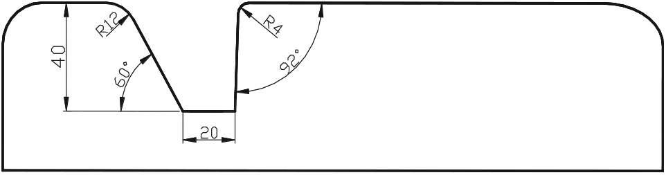
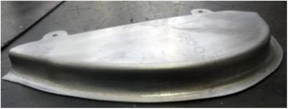
Figure 2 shows a typical part with high curvature and large flange. The height of the flange, h, was 25 mm. The radius of the fillet, r, was 4 mm. The radius of the die, R, was fitted to 88 mm. The material was 2A12-O, which is similar to that of 2024-O. Table 1 shows the material parameters. In Table 1, E is Young’s modulus; K is the strength coefficient; γ is Poisson’s ratio; σs is the yield strength; n is the strain-hardening exponent; and

Typical part with high curvature and large flange.
Material parameters.


Experimental result.
Side blankholder method
Geometric analysis
Wrinkling control is the key problem in the shrink flange forming process. There are many methods to control the wrinkling. The side blankholder is one of the main methods. 20 Figure 4 shows the scheme of the side blankholder used in the rubber forming process. The blank is supported by the side blankholder and gradually pressed to the die by the rubber force. The wrinkles will not occur due to gradual contact. The design of the parameters of the side blankholder is very important and has a large effect on the forming process. The parameters include the angle of the side blankholder, a; the blank length on the side blankholder, b; the fillet radius of the side blankholder, c; and the bottom gap between the die and the side blankholder, d.
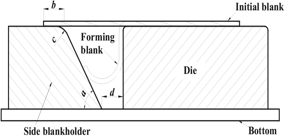
Side blankholder method.
Finite element simulation
In order to study the effects of the parameters (a, b, c, and d) on the forming process, finite element simulation was used to analyze the rubber forming using different side blankholders. Figure 5 shows the finite element model. There are five parts in the finite element model: blank, rubber, die, side blankholder, and bottom. The blank and the rubber are deformable bodies. The die, side blankholder, and bottom are rigid bodies. The forming process was simulated by ESI Pam-Stamp. The element used in this study was a four-node B-T shell. Five layers in the thickness were used in the B-T shell element. The yield model was that of Barlat and Lian. 21 The mesh size of the blank was 1 mm. The Coulomb friction coefficient of the contact surface was 0.1. The rubber pressure was 30 MPa. These simulation parameters have been optimized and proved to be effective for rubber forming. 22

Finite element model.
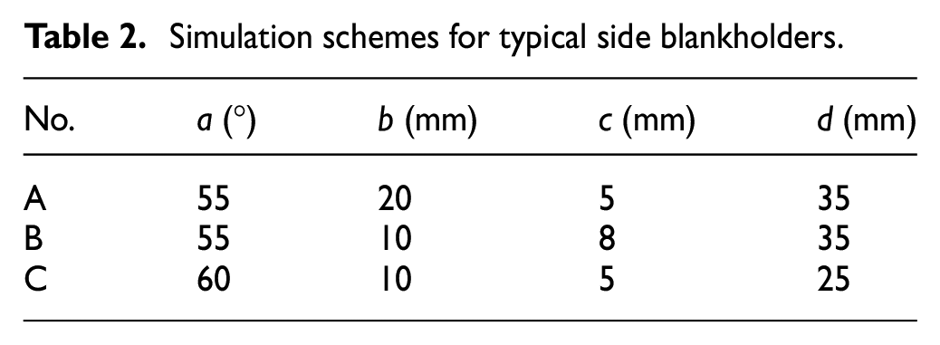
Many simulations have been done to compare the effects of different parameters on the forming results. The size ranges of the a, b, c, and d are 50°–60°, 5–20 mm, 5–10 mm, and 20–35 mm, respectively. Table 2 shows the typical simulation schemes using different side blankholders. Figure 6 shows the simulation results using these schemes:
Scheme A: The blank length on the side blankholder, b, is 20 mm. The bottom gap between the side blankholder and the die, d, is 35 mm. It can be seen that cracking occurs in the fillet of the part (see Figure 6(a)). Due to the long blank length, the blank flow is difficult. The deformation of the blank is focused in the fillet.
Scheme B: The blank length on the side blankholder, b, is 10 mm. The bottom gap between the side blankholder and the die, d, is 35 mm. It can be seen from Figure 6(b) that the blank was drawn in, and there are some large winkles on the flange. This is because the bottom gap is too large. The blank has no support in the gap between the side blankholder and the die.
Scheme C: The blank length on the side blankholder, b, is 10 mm. The bottom gap between the die and the side blankholder, d, is 25 mm. It can be seen that the blank was drawn in, and there are some small wrinkles on the flange (see Figure 6(c)). With the decrease in the bottom gap, the wrinkles move to the edge of the flange. This scheme is good for manufacturing with the cut of the edge.
Simulation schemes for typical side blankholders.

Typical simulation results: (a) Scheme A, (b) Scheme B, and (c) Scheme C.
Based on the results of scheme C, the effects of different factors on the forming results were studied. Table 3 shows the simulation results using different factors. As observed from No. 1, 2, and 3, the minimum thickness increases with the increase in the angle of the blankholder. The reason is that the resistance force of the side blankholder decreases with the increase in the angle of the side blankholder, a. As observed from No. 1, 4, and 5, the minimum thickness increases with the decrease in the blank length. The blank length on the side blankholder, b, should be small enough. As observed from No. 1, 6, and 7, the minimum thickness increases with the increase in the fillet radius. The fillet radius of the side blankholder, c, should be large enough to reduce the deformation. As observed from No. 1, 8, and 9, the minimum thickness increases with the increase in the bottom gap. The bottom gap between the side blankholder and the die, d, cannot be too large because the support of the blank will decrease in the forming process (see Figure 6(b)).
Simulation results using different factors.

Experiment
According to the finite element analysis, the side blankholder and the die were designed as shown in Figure 7. The parameters a, c, and d were 60°, 12 mm, and 20 mm, respectively. Figure 8 shows the photograph of the manufacturing die. In order to verify the simulation results, three blank lengths (20, 15, and 5 mm) on the side blankholder, b, were used in the experiment. Figure 9 shows the experimental results. The forming part splits when the blank length, b, was 20 mm (see Figure 9(a)). This agreed well with the simulation scheme A (see Figure 6(a)). There were some large wrinkles in the flange when the blank length, b, was 15 mm (see Figure 9(b)). The blank was not drawn in completely due to the large blank length, and this agreed well with the simulation scheme B (see Figure 6(b)). The blank was drawn in completely when the blank length was 5 mm (see Figure 9(c)). There were some small wrinkles in the edge of the flange, and this agreed well with the simulation scheme C (see Figure 6(c)). After cutting the surplus material, the wrinkling of the part was controlled. The results of the comparison tests testified the reliability of the simulation. The optimal parameter of the blank length, b, was 5 mm.
Section of the side blankholder and the die.

Photograph of the die and the side blankholder.
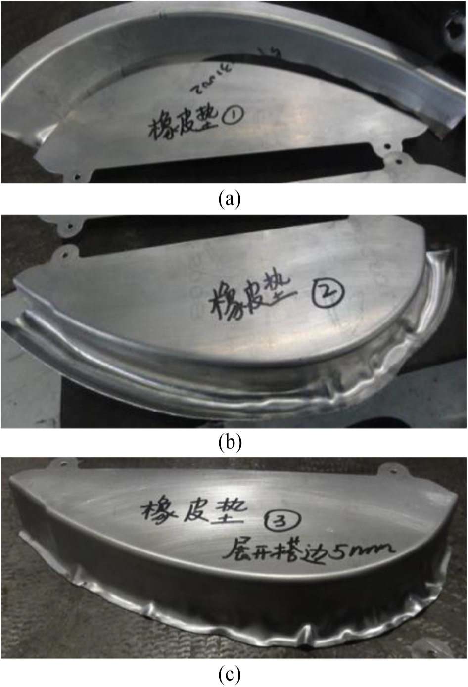
Experimental results with different b: (a) 20 mm, (b) 15 mm, and (c) 5 mm.
Clamp method
Analysis and design
The wrinkling in the flange can be controlled using side blankholder with optimal parameters, while there are some wrinkles in the edge of the forming parts. These wrinkles need to be cut off after rubber forming. It is a time-consuming operation, which often leads to some deformation of the parts due to stress redistribution. The blank is larger, and it is not economical. Precision forming is the trend in sheet metal forming at present. We need to design a new method for wrinkling control to fulfill net forming.
Figure 10 shows the design scheme of clamp method for wrinkling control. Initial blank was put on the die and fixed. Then, the flange was clamped and pressed to the bottom by the rubber force gradually. The wrinkling would not happen because of the progressive deformation. Figure 11 shows the newly designed combined mold. The combined mold contains five parts: two clamps, rubber, frame, and die. The die and the rubber were put into the frame. The clamps were put on the rubber within the frame. The blank was fixed on the die and clamped by two clamps. Figure 12 shows the manufactured combined mold.

Design scheme for wrinkling control.

Combined mold: (a) upper die and (b) lower die.

Photograph of the combined mold.
Experiment and result
The parts were formed in a rubber forming press. First, the combined mold and the blank need to be assembled. Figure 13 shows the assembling process of the combined mold. The die was put into the frame. Three layers of rubber plates were put in the frame, as seen in Figure 13(a). There was an interval of about 30 mm between the rubber plates. The height of one layer of the rubber plate was 10 mm. The width of the rubber plate was 30 mm. Figure 13(b) shows the net blank. Two pinholes were added. The blank was clamped by two clamps, as seen in Figure 13(c). In order to reduce the friction force in the forming process, the blank and the clamps were painted with castor oil.

Photographs of mold assembling: (a) rubber plates, (b) initial blank, and (c) clamp.
In the experiment, the hardness of the rubber plate has a large effect on the forming results. First, the rubber plates with Shore hardness A55 were used. The forming pressure was 35 MPa. Figure 14 shows the photograph of the part. We can see that the wrinkles in the flange disappear, but the flange was not pressed completely. The experimental results were similar by increasing the forming pressure. So, we modified the hardness of the rubber plates to Shore hardness A35. Two layers of the rubber plates were used. Figure 15 shows the photograph of the part after forming. From Figure 15, we can see that the forming part was perfect. The wrinkling did not occur. The precision of the part met the requirement. Based on the experimental results, we can conclude that the whole height of the rubber plates is not larger than half of the height of the die. There is sufficient clearance (>30 mm) between the two rubber plates.
Experimental result using Shore hardness A55 rubber.

Experimental result using Shore hardness A35 rubber.
Conclusion
The height of the flange is the key factor to control wrinkling on the basis of theoretical analysis. The forming parameters and die structure need to be designed to control the wrinkling for large flange. The effect factors of side blankholder method were analyzed by finite element simulation. With the increase in the angle of the blankholder, the resistance force of the blankholder decreases. The blank length on the side blankholder should be small enough. The fillet radius of the side blankholder should be large enough to reduce the deformation. The bottom gap between the die and the side blankholder cannot be too large because the support of the blank will decrease in the forming process.
A new clamp method was designed for wrinkling control to overcome the shortcomings of the side blankholder method. The flange was clamped and pressed to the bottom by the rubber force gradually. The wrinkling would not happen because of the progressive deformation. The hardness and height of the rubber plates have large effects on the forming results. The whole height of the rubber plates is not larger than half of the height of the die. There is sufficient clearance (>30 mm) between the two rubber plates. The precision of the part met the requirement using soft rubber and two layers of rubber plates.
Footnotes
Acknowledgements
The authors would like to thank Professor M. Ding, Qiu Xi, and Li Shanliang for their guidance and Jia Min, Qiao Fengmin, and Cai Yanmin for their help in the study.
Handling Editor: James Baldwin
Declaration of conflicting interests
The author(s) declared no potential conflicts of interest with respect to the research, authorship, and/or publication of this article.
Funding
The author(s) disclosed receipt of the following financial support for the research, authorship, and/or publication of this article: The research was supported by the National Natural Science Foundation of China (No. 51875146).