
Abstract
The purpose of this article is to propose an infinite variable transmission with orbital pulleys, which consists of two parallel transmission systems. The system comprises a planetary gear set and a continuously variable transmission. The principle of operation of the infinite variable transmission proposed in this article is based on the actuation of one half-sided pulley, which has a translational movement in a direction, and the same amount of movement is reproduced by the other half-sided orbital pulley in reverse to secure that the length of the belt remains constant. The fixed constant horizon enables the infinite variable transmission to change the transmission ratio from negative values to positive passing through zero in a continuous manner without using a clutch or interrupting the system. The dynamic model and prototype of the infinite variable transmission with orbital pulleys are developed for designing, controlling, and validating purposes. The model is obtained using the Euler–Lagrange methodology, and it is experimentally validated by comparing the proposed model with the experimental measures. The infinite variable transmission with orbital pulleys is controlled under different conditions; the experimental results show that the proposed design of infinite variable transmission provides robustness to maintain constant speeds at the output to changes at the input velocity.
Introduction
An infinite variable transmission (IVT) is a type of continuously variable transmission (CVT), which besides changing positive transmission ratios smoothly, can have negative transmission and zero angular velocity at the output despite the speed at the input to the system is different from zero. These advantages allow the IVT to optimize fuel consumption and improve the driving experience than its discrete counterpart, manual or automatic, in the automotive industry. 1 Other applications where an IVT can be used are wind turbines because it requires a variable speed ratio transmission that can run a generator at a constant speed and to enable the turbine rotor to capture maximum energy from the wind. 2 In robotics, IVTs can operate a knee joint with over 90% energy savings compared to a single-speed transmission. 3
Research has been conducted in two aspects: the first one is focused on analyzing aspects of modeling, for instance, physical phenomena that exist on the belt when transitions of the transmission ratio occur. The second aspect is in relation to proposing new configurations of IVT to make them more efficient and compact.
According to the first aspect, much research has been conducted on the dynamic modeling of CVT. Most existing models of the CVT are based on principles of quasi-static equilibrium. In studies by Kim and Lee 4 and Gerbert, 5 a set of equations that capture the interactions between the belt and pulley are developed. Because the belt can move both radially and tangentially, an approximation of a sliding variable angle is used for describing the friction between the belt and pulley. Gerbert 5 also studied the effects of bending and dynamic inertia rubber belt. Again, only the centripetal effects were modeled to be considered by inertia.
Gerbert and Sorge 6 developed a third-order model for the V-band rubber belt, introducing a new concept called “adhesive-like.” The model does not take into account either the bending or inertial effects. In that paper is proposed that the belt does not stick to the wall pulley around the arc of contact, but there is a region where a landslip occurs at a very low speed.
Julio and Plante 7 proposed a model of the CVT dynamics of a rubber belt. Newton’s laws of motion and a quantization belt are employed to solve the model using numerical methods. Each discrete element takes into consideration vectors such as tension attached to each node, radial force, axial force applied to the pulley, friction force in the belt, and an equivalent force of the bending moment. In this model, it is not considered inertia of the belt but its mass, which is divided by the number of nodes in the discretized model. The conclusion obtained is that the model works fairly accurately when changes in transmission ratio occur slowly.
Karam and Play 8 also reported a discrete analysis of a metal V-belt drive where a quasi-static equilibrium analysis is used. An extensive review of the dynamic modeling of belt and chain CVT and CVT control are shown by Srivastava and Haque. 9
According to the second aspect, many kinds of IVTs have been proposed according to the physical principle of operation such as friction,10–15 fluid flow guide, 16 or the torque and speed converted to pressure and flow rate.
Bottiglione and Mantriota17,18 developed an IVT, which consists of the usual components a CVT, a planetary gear train, and a constant transmission ratio mechanism. Two types of different power flows are obtained via clutches. Lahr and Hong 19 analyzed the operation and kinematics of a cam-based IVT. The cam is seen as the input and the sun gears as the output. All the sun gears are connected to a shaft using individual indexing clutches.
Berselli 20 studied an inertia-type IVT; the system includes a four-bar linkage mechanism, an epicyclic gear train, and a pair of one-way clutches. A pulse-drive IVT is proposed by Tsuchiya and Shamoto; 21 the rotational speed and torque is achieved by controlling the engagement time of compact slipless clutches. This principle is similar to duty control in electronic voltage converters, which utilize the ratio of engagement time rather than that of turns of coils.
A nested pulley configuration of the IVT-OP is proposed in Kembaum et al. 22 The CVT is a modified planetary gear, where the planets are turned into tilted cones. The ring is made up of rollers and can translate along with the cones to change the contact point radius and then the transmission ratio. Moreover, a three-dimension (3D)-printed continuously variable strain wave transmission (CVSWT) is built by Naclerio et al. 23 This conceptual design employs a magnetic strain wave gear, compressed metal rollers, a variable planetary gearing drive with small conical rollers, systems with orbiting pulleys, 24 and a variable transmission using nested pulleys. 22 The authors suggest that the CVSWT is suited for low-cost, low-weight applications that do not depend on a high degree of positional accuracy or stiffness.
In this article, a mechatronic IVT with orbital pulleys (IVT-OPs) is addressed. The two main contributions of this research are as follows: (1) the mechatronic design proposal to be able to control the transmission ratio to different speed and torque references, which is achieved by the novel design of a half actuated pulley. Also in this design, the inertial effects due to the orbital pulley are reduced. (2) Unlike the quasi-static models found in the literature, in this article, a dynamic model for the proposed IVT-OP is obtained and experimentally validated. Moreover, the proposed dynamic model considers changes in transmission ratio, which is time variable, when the automatically driven pulley is actuated at different operating conditions.
In section “Conceptual design” is shown the design of the pulleys such that it is possible to change the effective radii by an actuator, both the drive pulley and the driven pulley. Where particular attention is taken with the drive pulley, which is one of the key elements throughout the IVT-OP. The kinematic and kinetic model is obtained in section “Modeling.” Section “Model validation” demonstrates the model validation. Experimental results under different operating conditions are presented in section “Experimental results.” The proposed operating conditions are tracking step and ramp speed profiles at the output with a constant input speed. Control of a constant reference in the output velocity against speed changes in the input, as well as torque control in the output. Finally, conclusions are presented in section “Conclusion.”
Conceptual design
The proposed IVT-OP consists of two parallel transmission systems. The first system consists of a gear planetary train joined to a flywheel (Figure 1(a)), whose purpose is to maintain the fixed horizon. The fixed horizon 24 provides the ability to change the transmission ratio from positive to negative and vice versa. The fixed horizon works in the following way. The central gear is attached to the fixed frame (Figure 1(b)). The second element is an idler gear, and the third one is the orbital gear. The orbital gear can translate circularly, and it is supported by the flywheel and the idler gear (Figure 1(a)). The central and the orbital gear must have the same pitch diameter to avoid rotation in the driven pulley when it transmits torque to the driver pulley (Figure 1(b)). Therefore, a horizontal line in the orbital gear remains while this orbital gear translates around the central gear. A shaft attached to the orbital gear is as well fixed to the half-fixed orbital pulley (Figure 2). Both orbital gear and driven pulley turn simultaneously without relative angular displacement between them. Collinear with the fixed central gear is the driver pulley which is attached to the driven pulley through a multi-speed rubber V-belt.

Conceptual design IVT-OP: (a) schematic IVT-OP and (b) CAD design IVT-OP.
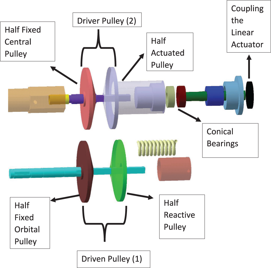
Pulleys explode.
The second system consists of two variable pulleys (CVT), whose function is to change the transmission ratio. According to the desired transmission ratio, the linear actuator pushes or pulls the half-actuated pulley, providing enough energy that both driver and driven pulley change their operating diameters. In the case of the driven pulley, both halves orbit but only the half reactive pulley (Figure 2) moves translationally on the shaft which is attached to the first transmission system. This translational movement is caused by a spring, which reacts to the pressure in the pulley. The driver pulley rotates but just the half-actuated pulley also translates. Conical bearings, bushings, and flanges are installed in the half-actuated pulley in such a way that it is possible to move it along with the linear actuator. Besides, this configuration allows transmitting the rotational movement to the load. Inside the half-actuated and reactive pulleys, a rectangular hole is required to allow the translational and rotational movement without sliding on the plane in which the translation takes place.A tensioning pulley is necessary precisely to maintain tension on the belt at any instant of operation. In addition, the tensioning pulley reduces the distance between the pulleys and, in consequence, inertia is minimized at the same time.
At the right end of the half-actuated pulley, there are two different depths and different diameter holes. In the smallest diameter hole, tapered roller bearings are installed. The narrowest ends of the bearings are face to face. In order to prevent translational movement of these bearings a screw cap keeps them pressed against the inner wall of the pulley. Inside this cap is a bushing which together with the bearings supports the shaft pushing or pulling the half-actuated pulley. Finally, a gear mounted on the half-actuated pulley transmits power to the output shaft.
The conceptual mechatronic prototype, as well as the coupling with the input motor, encoders, the linear actuator that acts on the driver pulley, and the torquimeter is shown in Figure 3. To obtain the input velocity, the position obtained with the encoder US Digital S2-2048-B 25 (Input Encoder) was derived using MATLAB (Simulink). Second, to measure the output speed and torque a FUTEK (a torque sensor distributor in North America) model TRS605 sensor is used. To measure the translational displacement in the driver pulley, an analog linear potentiometer is installed between the driver pulley and the load.
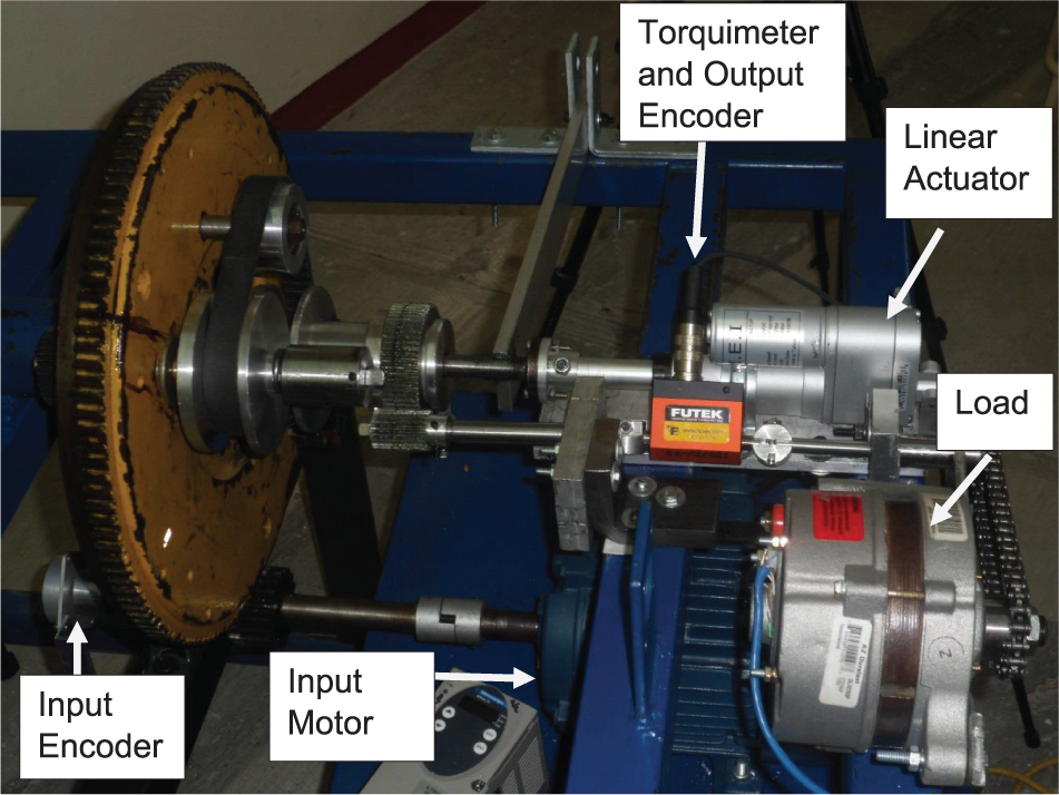
Experimental setup.
The card Sensoray model 626 (an embedded electronics distributor in North America) is used for data acquisition and is used with the real-time toolbox of MATLAB. Such a card has two modules for 48 channels of digital I/O, two modules for eight quadrature encoder inputs, and one module for digital inputs and outputs.
Modeling
In this section, the kinematics and kinetics of the proposed IVT-OP are analyzed. First, the kinematics of planetary gears is explained after the kinematics of the pulleys is analyzed. The transmission ratio is obtained at the end of the kinematics section. The transmission ratio is used to connect the input and output speeds in the system to express the dynamic model in terms of just one generalized variable.
Kinematics
It should be noted that all kinematic analysis is done with the angular velocity and not with the angular position because it is in angular velocity where the time variable transmission ratio has a physical meaning in the dynamic model.
The mechanism, guaranteeing the fixed horizon, is shown in Figure 4.

Gear kinematic.
As shown in Figure 1(a), the central gear (A) is attached to the frame; therefore, its angular velocity is equal to zero. The following equations describe the relationship between planetary gears and flywheel. Nomenclature is presented in the last part of this article

Substituting

Considering

As there is an orbital shaft attaching orbital gear (C) to the driven pulley (1), Figure 5, the angular velocity in the driven pulley is equivalent to the angular velocity in the flywheel as expressed in equation (4)


Pulleys kinematics.
Substituting

From equation (5), the transmission ratio between the output speed

From equation (6), it can be seen that when the radii on the pulleys are equal, the neutral operating point is reached. When radius
Kinetics
Although it is possible to find machinery where static transmission ratios are used, there are mechatronic applications such as robots and wind turbines where a dynamic transmission ratio can improve the performance of the entire system. In the case of a robot that reaches the desired position and the gravity acts against the link, the motor could omit the use of the dynamic brake, taking the IVT-OP to the neutral operating point. The IVT-OP can be used to maintain a constant speed output in the generator despite changes of speed on the blades. The two examples cited before are the motivation to present the dynamic model of the IVT-OP. Likewise, analyzing the behavior of the transmission ratio when pulleys change their radius to follow the desired speed profile.
To obtain a time variable transmission ratio, it is necessary to know how to change the radii linear function of displacement of the pulleys. When the half-actuated pulley is retracted by a distance X, the belt moves down a distance Y (Figure 6). The left side of Figure 6 shows the half-actuated pulley in two different operating times. On the right side of Figure 6, the half-fixed central pulley is depicted. The half-fixed central pulley does not have translational movement due to the pressure of the V-belt. The dotted line symbolizes the width of the V-belt, which touches the walls of the two pulley halves.

Displacement of the V-belt.
Based on Figure 6, the next equation can be stated

The initial radius of the pulley must be previously known to add or subtract the distance

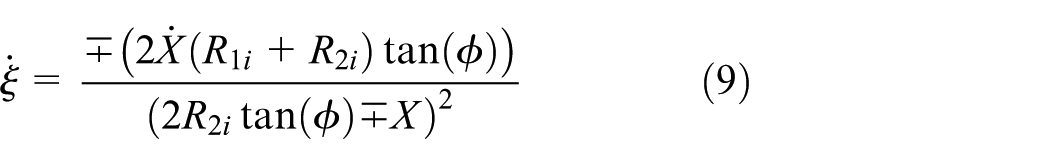
The variation of the transmission ratio over time,
Input and output positions, velocities, and accelerations are required so the general model can be expressed in terms of just one variable and it can be compared with experimental results. Inputs and outputs are related through the transmission ratio as

Deriving equation (10), it holds the following

Finally, to obtain the output position,

Some assumptions are taken into consideration.
Viscous friction is considered in different elements such as bearings and bushings.
Displacement in magnitude is the same in the driven and driver pulley.
The V-belt weight is neglected.
Shafts, gears, and pulleys are rigid.
First, the Euler–Lagrange methodology is used for finding the dynamic model of the mechanical system. Therefore, the driving torque can be expressed as

Input torque, Figure 1(a), at the input shaft is given by

The torque between the coupled pinion to the Input Shaft and the Flywheel is directly proportional to the ratio of the number of teeth

Torque in the driven pulley is given by

Combining equations (14) and (15) with (16)

This equation can be expressed only in terms of the torque applied at the driven pulley, as

The driver pulley torque is given by

Likewise, the torque transmitted to the gear of the output shaft (Figure 1(a)) is

Equations (19) and (20) are related by the ratio of the number of teeth
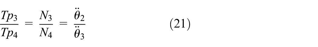
Combining equation (20) with equation (21), we obtain

Equation (22) in terms of the output variable of the driver pulley can be written as

The relation between the driver pulley, equation (23), and the driven pulley, equation (18), is established through transmission ratio:
The position

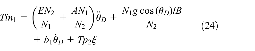
where
where
Equation (25) relates the input torque provided by the motor and the dynamics in the driver pulley considering all the elements that constitute the IVT-OP. The model obtained is a non-linear ordinary differential equation which is undetermined when the transmission ratio approaches the neutral operating point. The kinetic indeterminacy generates that the torque at the output tends to infinity as the transmission ratio tends to the neutral point of operation.
IVT-OP efficiency
The flowchart, Figure 7, shows the power flow existing in the IVT.

Power flowchart of the IVT-OP.
As shown in the flowchart, the efficiency of the IVT-OP

In the literature, different dissipative phenomena are reported that impact on the efficiency of transmissions with straight gears. Depending on the relative movement, it can be classified as friction by sliding and rolling. Friction can be generated by sliding between two solid bodies, between layers of fluids, friction by rolling due to deformation of the profiles and fluids. A complete review of the state of the art on efficiency in straight gears can be found at Díez Ibarbia. 26
In the case of a rubber V-belt CVT, the loss of efficiency is due to torque loss or speed loss. Factors that impact on torque loss are due to bending hysteresis, wedge-in, and wedge-out, radial sliding motion and compression. Factors that impact torque loss are due to belt extension, rubber compliance, shear deflection, seating, and unseating. 27
Model validation
To validate equation (25), the output angular velocity has been compared to measurements on the IVT-OP (Figure 8). In Figure 8, the dotted line symbolizes the output speed of the IVT-OP, while the continuous line represents the model given by equation (25). The system starts from rest until the input shaft reaches a constant speed of 420 r/min. The initial configuration of the IVT-OP starts in a reverse transmission ratio until it reaches a positive one following a ramp-type reference. The spring starts from rest at the installed length until reaching the operation length, where the spring reaches the maximum working load. When the driven pulley arrives at the operation length, the linear actuator, which moves the driver pulley, activates its limit switch. The activation of the limit switch sensor marks the end of the positive transmission ratios.

Validation of the IVT-OP dynamic model.
The absolute error, which is the amount of physical error in

Absolute error.
Experimental results
This section shows results for different operating conditions of the IVT. In the first case (Figure 10), the flywheel has a constant input speed. Three stepped speed references at the output of the IVT-OP are required. Figure 10 shows the first step reference at 5 r/min and stays for 30 s. Then the second step reference is at 0 r/min and it is kept 20 s. The last step reference is 5 r/min negative for 35 s. This type of operating condition is similar to a maneuver while parking in a parallel spot. Control gains for a proportional–derivative (PD) controller are set to Kp = 3 and Td = 0.0334. Initial conditions are set to zero.
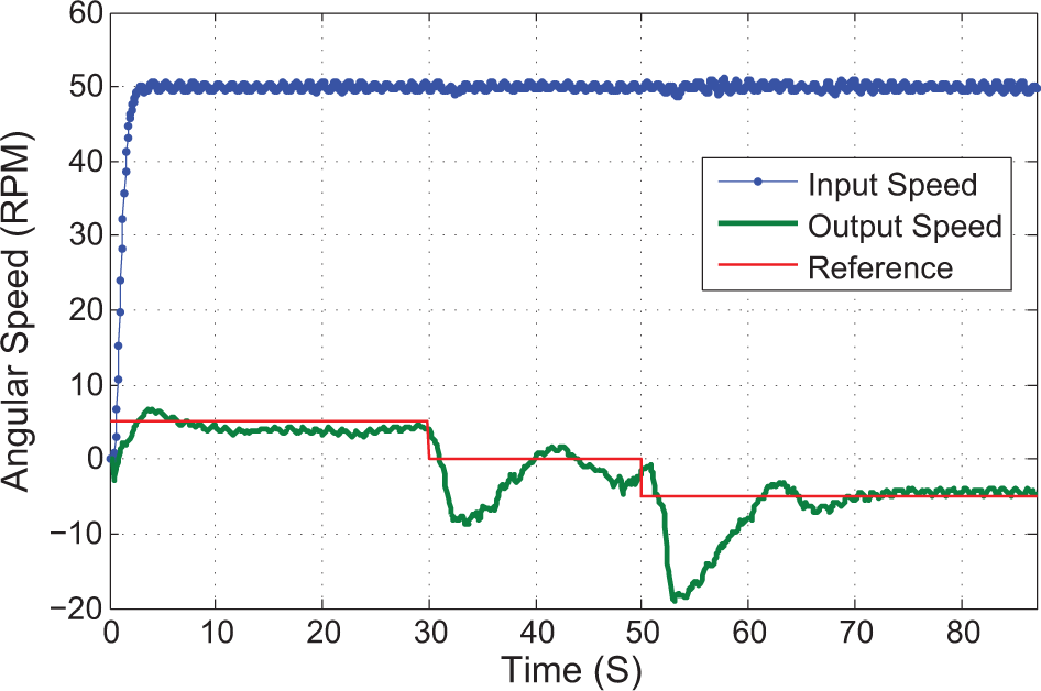
Speed control steps.
In the second experiment, shown in Figure 11, a ramp with a negative slope is requested as a reference. This type of operating condition is similar to a maneuver while parking in a perpendicular spot. In Figure 11, it can be seen that the angular velocity starts from positive angular velocity and ends with negative angular velocity. Control gains used in this experiment are the same as those used for the previous graph. Initial conditions are set to zero.
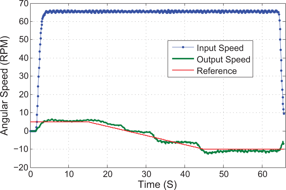
Speed control to a negative ramp reference.
Similarly, in Figure 12, a ramp with a positive slope is requested as a reference. This type of operating condition is similar to certain moments of operation of a robot performing pick and place operations. Besides, larger power is required by the actuator when it moves the driver pulley from negative to positive transmission ratios than otherwise. The need for more power is due to the potential energy of the spring when the system moves from positive to negative transmission ratios, the potential energy is released and the contraction of the linear actuator consumes less work than during compression of the spring. Therefore, the driver pulley moves faster. Control gains for this case are Kp = 3.6, Ti = 180, and Td = 0.0556. Initial conditions are set to zero initial velocity.
Speed control to a positive ramp reference.
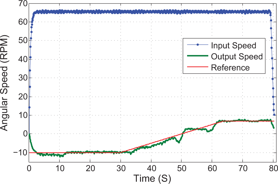
In the fourth experiment, a constant angular velocity at the output is required as a reference, while the angular velocity at the input is changing, as shown in Figure 13. This type of operation condition could be used in the case of wind turbines, in which a constant speed output is required despite the different speeds at which the blades can be moved. From Figure 13, it is observed that speed changes of 15 r/min at the input represents a disturbance of 2 r/min at the output of the IVT-OP, which makes the IVT-OP a viable solution for wind turbine applications, since it would reduce the cost of electronic circuits such as voltage regulators and peak suppressors. Control gains for this case are Kp = 1.05, Ti = 8.75, and Td = 0. Initial conditions are set to 67 r/min as initial velocity.

Constant output speed to changes in the input speed.
Finally, Figure 14 shows changes at the output speed of the IVT-OP when the load shows torque perturbations. When load changes the magnitude and direction of rotation, the IVT-OP changes its output angular velocity in the opposite direction to the load. For example, when disturbances are generated at the output of the IVT-OP in the clockwise direction, the angular velocity at the output of the IVT-OP is positive, as it can be observed in the first 15 s of the experiment (Figure 14). On the contrary, when the torque disturbance at the output occurs in the anticlockwise direction, the angular velocity at the output of the IVT-OP is negative as can be observed at approximately 20 s (Figure 14). This kind of behavior is desirable in apparatus for direct physical interaction between a person and a general purpose manipulator controlled by a computer because they react in the opposite direction by changing their transmission ratio when load opposition is found. The control gains are set to Kp = 120, Ti = 30, and Td = 0.

Torque control.
Figures 11 and 12 show that changes in the transmission ratio are made smoothly on ramp-type references. On the contrary, the rearrangement of the pulleys is more abrupt in the case of step-type references (Figure 10). In the case of step-type references, it takes about 7 s for the IVT-OP to reach the reference, although the response speed depends on the magnitude of the load and the power capacity of the linear actuator.
Conclusion
In this article, an IVT-OP has been presented. Two parallel mechanisms have been used to avoid using clutches or power-split principles to achieve forward, reverse, and neutral. Since a clutch is not required to make changes in the transmission ratio, these changes occur continuously and smoothly without jerks. In addition, the fixed horizon, which is constructed in this particular case with three gears, allows reducing the number of parts necessary to build up the IVT. The viability of applying the IVT-OP in robotics, automotive, and wind turbine fields has been exposed in the experimental results. The model of this system has been analyzed and verified using a systematic methodology. A precise agreement has been found between the model and experimental results in steady state and during shifting maneuvers.
One of the main advantages in the control of the transmission ratio in a dynamic way is the ability to improve the efficiency of the whole system by bringing the engine closer to its point of the best-operating efficiency. Also in the case of robotic applications, the use of the dynamic brake could be omitted by taking the IVT-OP to a neutral operating point, where according to the model in the neutral position, there is high mechanical opposition to the movement.
Footnotes
Appendix 1
Handling Editor: James Baldwin
Declaration of conflicting interests
The author(s) declared no potential conflicts of interest with respect to the research, authorship, and/or publication of this article.
Funding
The author(s) received no financial support for the research, authorship, and/or publication of this article.
Supplemental material
Supplemental material for this article is available online.
References
Supplementary Material
Please find the following supplemental material available below.
For Open Access articles published under a Creative Commons License, all supplemental material carries the same license as the article it is associated with.
For non-Open Access articles published, all supplemental material carries a non-exclusive license, and permission requests for re-use of supplemental material or any part of supplemental material shall be sent directly to the copyright owner as specified in the copyright notice associated with the article.