
Abstract
Vibration generated by engine and its accessories deteriorates product performance. At present, lacking global model, mounting design of engine and accessories are separate, not conductive to solving the vibration of engine, belt, and accessories as a whole. In this article, three problems of the typical structure are analyzed, that is, the belt tension is unstable, static preloading makes engine mount design deviate, and the belt is prone to lateral vibration. Then, a rigid constraint rod is proposed to fix the center distance. The vibrational motion equation is established. By matrix analysis, the accessory mount along the rod is canceled. Then, engine and accessories can be analyzed as independent systems. Among them, the vibration isolation of the engine tends to be good, and for accessories and belts, the influences of the accessory mount stiffness on the force and torque transmission rate and belt vibration response were comprehensively evaluated, and that the infinite stiffness is presented. The innovative design of five-rod structure mainly composed of two connecting rods is obtained which does not transfer vibration perpendicular to rod and the vibration of engine, belt, and accessories are all well controlled. This experiment proves the five-link structure as a useful solution.
Introduction
Engine–accessory system is a common configuration of many mechanical products. Engine and accessories are vibration excitation sources to belt, and belt is easily excited to resonance. Any one of the three can seriously affect the sound and vibration of mechanical products. At present, the research of engine, belt and accessory is mainly carried out independently.
Vibration of powertrain and accessories is mainly controlled by mounting system. A powertrain consists of an engine and other parts, such as a gearbox, that is rigidly connected to the engine. The powertrain and its mount system constitute the powertrain mounting system. Powertrain is generally treated as a rigid body, and the passive end of the mount is treated as a foundation of infinite stiffness and mass. 1 The optimized parameter variables include mount position, stiffness, damping and mounting angle, and so on. 2 There are mainly two kinds of optimization objective at present, one is to make the rigid modal frequency in a reasonable distribution range, and reduce the coupling between the modes, namely maximize the mode energy in each direction.3–5 Another optimization goal is to minimize vibratory forces transmitted through the elastomeric mounts under certain engine excitation conditions.6,7 Courteille et al. 8 and Xie et al. 9 adopted the multi-objective genetic algorithm to solve the multi-objective robust optimization problem.
The vibration control of belt is studied in the front-end accessory drive system which consists of several belt pulleys and belts. It includes the continuous lateral vibration of belt and the rotary vibration of belt pulleys. Based on the string’s dynamic model, Ulsoy et al. 10 established the linear coupling equations of the lateral motion of the belt and the rotary motion of the tensioner. Zhang and Zu 11 extended the string model to non-linearity and analyzed the parameter resonance of coupled vibration. Shangguan et al. 12 estimated the natural frequency and displacement of the coupling model of the pulleys and string. One-way clutch is an effective way to reduce belt vibration, and its function is similar to that of vibration absorber.13,14
Although, the above research methods can achieve certain results in local vibration control, due to ignoring the interaction between the three research objects of engine, belt, and accessories, it is difficult to guarantee the overall vibration control. Rare reports on the study of engine–belt–accessory as a system, in view of the deficiency in this aspect, this article mainly carries out the analysis and research on the mechanical model and mathematical model of the engine–belt–accessory system. Since the excitation and responses are mainly in the plane, computational costs can be reduced and computational efficiency during the establishment of a mechanical model can be improved, 15 the complex three-dimensional problems are simplified to plane problems for analysis in this article.
This article takes the engine–belt–accessory of typical structure of a passenger car as the research object. First of all, the three structural defects are analyzed, that is, the belt tension is unstable due to the change of pulley center distance, static preloading makes engine mount design deviate, and the belt is prone to lateral vibration. According to the problem caused by the change of center distance, a rigid constraint rod between the engine and the accessory is proposed to fix the center distance. Then, the mathematical model after adding this rigid constraint rod is established. Based on the analysis of the stiffness matrix, the cancelation of the mount of the accessory subsystem along the rigid constraint rod is put forward. Then, after ignoring the tiny coupling term in the mass matrix, the engine subsystem and the accessory subsystem can be analyzed separately. Among them, the vibration isolation of the engine subsystem is in a good direction and no further study is needed.
The accessory subsystem can be simplified as a 2-degrees of freedom (2-dof) system, and the influence of the stiffness on the force transfer rate and vibration displacement is studied. Based on the comprehensive consideration, we think that the infinite stiffness is the best solution, that is, the second rigid rod is proposed. So far, an innovative five-link-rod structure consisting mainly of two mutually perpendicular connecting rods is deduced. Test on a passenger car shows that the vibration of the engine, the accessory and the belt are well controlled. For engine and its accessory systems in various mechanical products, the five-link-rod vibration isolation structure proposed in this article is a beneficial solution to the problem of vibration of engine, belt, and accessory.
Proposal of rigid rod constraint scheme for engine–accessory
Defects of independent mount design
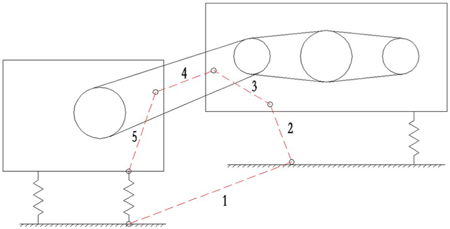
Typical design scheme of the engine and accessory is shown in Figure 1. The engine and accessory are connected by the main belt. All the accessories are rigidly fixed on the accessory frame. The accessories in this article include air conditioner compressor and generator.

Typical design of engine and accessory: (a) engine and accessory and (b) mechanical model by plane analysis.
At present, lacking the global model, the mount design of both the engine and the accessory is designed independently, which has the following three problems. (1) Because of independent mount design, the vibration of the engine and the accessories is also independent, resulting in the change of center distance of belt pulley, which makes the belt tension unstable and fluctuating greatly. In order to alleviate this problem, a tension spring is added in the original typical design. (2) Tension forces generated by the main belt make the engine’s mount produce great preloading and additional deformation. As the mount stiffness is greatly influenced by preloading, 16 this will result in a large deviation from the mount system original design. (3) The vibration of engine subsystem and accessory subsystem can be decomposed into transverse vibration component, perpendicular to the main belt, and longitudinal vibration component, along the belt. The transverse vibration component is the source of excitation for belt transversal vibration, and the longitudinal vibration component can make the belt tension change with time. For the transverse vibration natural frequency of the belt is affected by belt tension, therefore belt is prone to transverse vibration, and often resonance.
Put forward of rigid constraint link-rod scheme
For the first problem, namely, the problem caused by the change of center distance, the traditional design is to alleviate the problem by increasing the tensioning spring, but there are still problems in the scheme, that is, the pulley center distance will still change to some extent, and the belt tension will also fluctuate. Therefore, we propose to add a rigid constraint link-rod to fix the center distance, and the first problem can be solved successfully. In the structural design, the rod is connected with the engine and the accessory rack by hinge. The belt tension required can be achieved by adjusting the length of the rod slightly. Now, the tension spring of the original structure can be canceled, as shown in Figure 2.
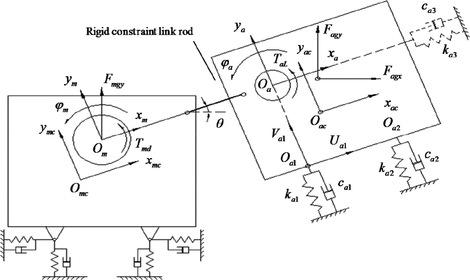
Mechanical model of adding a rigid constraint rod.
Since the force exerted by the rigid constraint rod on the engine is equal to and opposite to force that exerted by the main belt on the engine, the second problem is also solved at the same time.
Mathematical model of rigid constraint link-rod scheme
System equation of motion
The mechanical model after introducing the rigid constraint rod is shown in Figure 2. For the convenience of establishing the model, the horizontal coordinate axis is selected in accordance with the direction of the connecting rod, which has an angle
By adding a rigid constraint rod, the system dof in the two directions of
The five generalized coordinates adopted by the model are
Generalized coordinates adopted.

The system motion equation can be obtained by substituting the total kinetic energy, the total potential energy, and the total dissipated energy of the system into the Lagrange equation17,18

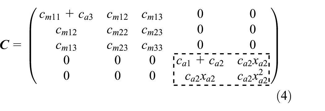
The generalized mass matrix, the generalized stiffness matrix, and the generalized damping matrix are shown in equations (2)–(4)
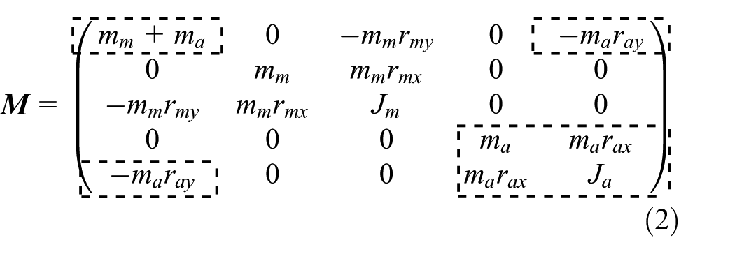

In the above equations, the subscripts m and a refer to the engine subsystem and the accessory subsystem, respectively. mm and ma refer to the quality of the engine and accessory, respectively.
The main driving sources in this case are engine, inline six-cylinder, and compressor, Vee-formation and four-cylinder. When analyzing according to the two-dimensional plane, there are seven excitations, namely, engine inertial driving torque
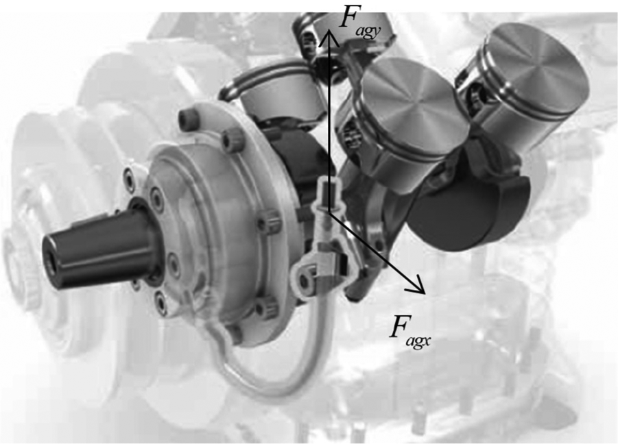
Internal structure of the compressor.
Since the effect and position of
The engine inertial force excitation
Engine driving torque
Horizontal component of compressor inertial driving force
Vertical component of compressor inertial driving force
Compressor load torque
According to the above analysis, the generalized force matrix of the motion equation is shown in equation (5), where

Analysis of system motion equation
By analyzing the generalized mass matrix
For the rod connection effect, the quality of accessory subsystem and stiffness along the rod direction
In the stiffness matrix
The size of the coupling term
Vibration isolation design of engine–accessory frame with rigid rod constraints
As shown in Figure 2, because both ends are hinged, the connecting rod only transmits the force along the rod between the engine subsystem and the accessory subsystem. Since
At the same time, the excitation force generated by the accessory subsystem itself along the
Analysis of the accessory subsystem transfer rate and belt vibration response
For the rod connection effect, the accessory subsystem is attached to the engine subsystem and vibrates with it in the
The generalized coordinates of the 2-dof vibration system are
The original structure of the engine subsystem and the accessory subsystem of a 9 m bus is shown in Figure 1. In order to solve the defects of the original typical structure, the scheme of adding one rigid constraint rod is adopted as shown in Figure 2.
At idle speed, the engine speed is 800 r/min. Due to a certain transmission ratio, the compressor speed is 900 r/min. Under this condition, the main excitations generated by the compressor are second-order, 30 Hz, and fourth-order, 60 Hz.
To be able to generate isolation, the natural frequencies of the 2-dof of
After selecting
Because the lateral vibration of main drive belt affects the whole vibration, for the engine and its accessory system, not only the better isolation performance is required, but the lateral vibration of the belt also needs to be controlled at the same time.
For the 2-dof vibration system of the accessory subsystem, in order to investigate the transmission of vibration and the lateral vibration of belt, we select three output variables of the system as follows: the transmission force
The amplitude frequency of force transfer rate

where

The amplitude frequency of torque transfer rate
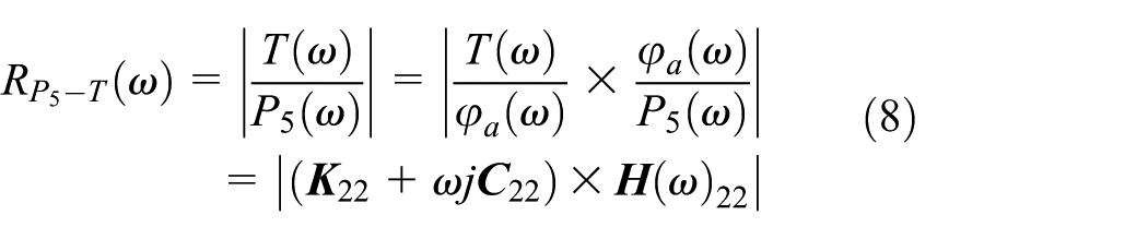
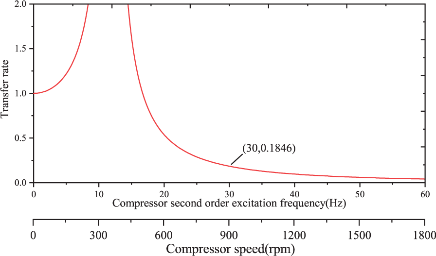
The calculated transfer rate curve is shown in Figure 4. The horizontal coordinate is excitation frequency, that is, the speed of the compressor and the compressor second-order excitation frequency.

Transfer rate of compressor excitation to the frame.
It can be seen that when the excitation frequency is 30 Hz, the force transfer rate is 0.3253 and the torque transfer rate is 0.1503, and the vibration is greatly attenuated.
Idle speed is the lowest speed, and 30 Hz is the lowest frequency of the compressor. This frequency is preferable for vibration isolation, and compressor vibration isolation will be better when rotating speed rises.
Therefore, adding rigid constraint rod and selecting
Matching of accessory subsystem mount
Although the vibration isolation performance is satisfied, we found the lateral vibration of the belt is still serious.
Keeping the stiffness

Changes of excitation transfer rates
From above definition,
As shown in Figure 5, there are three sections. When
Obviously the resonant region state in the middle is not desirable. When
When

A schematic diagram of a five-link-rod for engine–accessory system.
A diagrammatic drawing of a five-link-rod for engine–accessory system.
With the five-link-rod scheme, the excitation force transfer rate
As shown in Figure 8, when the excitation frequency is greater than 30 Hz, the torque transfer rate
Changes of the torque transfer rate
Application and test of vibration isolation scheme of five-link-rod mechanism
The application of five-link-rod structure for engine–accessory technology in a bus is shown in Figure 9. The thread rotation motion can be used to adjust the length of the rigid connecting rod to meet the belt tension. The stiffness

The application of five-link-rod structure for a engine–accessory technology in a bus: (a) assembly and (b) parts.
The point on the back seat skeleton in the bus is selected as the vibration evaluation point, as is shown in Figure 10(a).

The vibration evaluation point and test equipment: (a) vibration evaluation point and (b) test equipment.
The test equipment is shown in Figure 10(b). The main parameters of LMS data acquisition front-end are as follows: 24-bit analog-to-digital converter (ADC) and digital signal processor (DSP); SNR (signal-to-noise ratio) >106 dB; background noise: <−138 dB. The main parameters of accelerometer are as follows: sensitivity: 10.2 mv/(m/s 2 ), non-linearity ≤1%, frequency range 0.5–4500 Hz.
Compared with the previous structure, the belt runs very smoothly, and the vibration inside the vehicle is also greatly reduced.
The vibration acceleration of the original structure is compared with that of the new structure in bus three directions (front and rear, left and right, and vertical) of the acceleration measurement points on the floor, as shown in Figure 11.
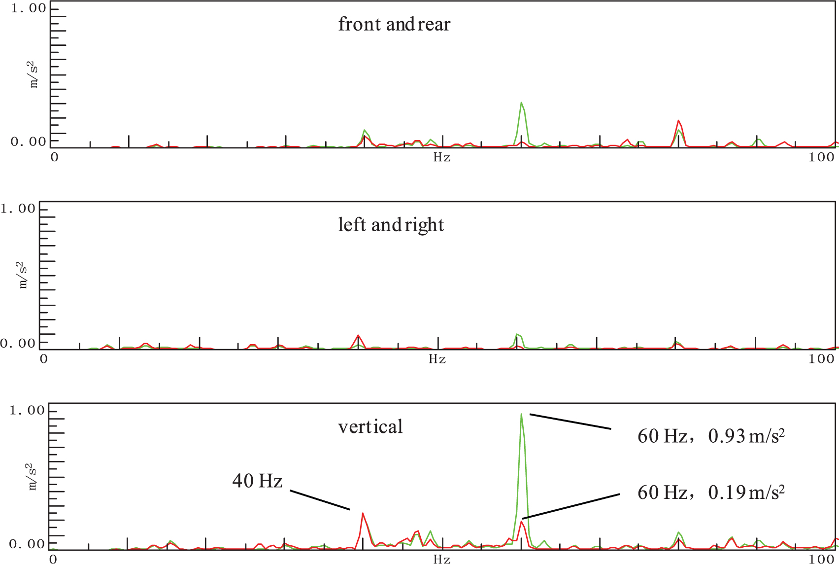
Comparison of vibration acceleration between the original structure and the five-link-rod structure on the rear floor of the bus.
In order to compare the vibration in each direction at the same time, the longitudinal coordinate range of the three directions in Figure 11 is set to 1 m s−2, which can intuitively show the main direction of vibration. As can be seen from Figure 11, the vibration inside the bus is mainly distributed in the vertical direction.
In the two structures, the interior vibration measuring point did not change significantly at 40 Hz generated by the engine in the third-order, while the 60 Hz vibration generated by the compressor in the fourth-order decreased significantly from 0.93 to 0.19 m s−2, with a decrease of 79.57%. At the same time, stable operation of belt can be observed.
Conclusion
Through the analysis of existing problems of engine and accessories typical structure, and the theoretical derivation and experimental verification, the following conclusions are obtained:
By adding a rigid constraint rod between the engine and the accessory, the problem of unstable tension and large static load of engine mount can be solved.
After adding the rigid constraint rod, the mount of the accessory subsystem along the connecting rod direction can be eliminated in the view of reducing natural frequency through matrix analysis.
For the engine subsystem, because the mass of the accessory subsystem is added in the mass matrix, the natural frequency also tends to be in a low direction, therefore, according to the vibration theories of the single free degree system, the vibration isolation tends to be in a good direction.
The influences of the accessory mount stiffness on the force and torque transmission rate and belt vibration response were comprehensively evaluated, the optimal scheme of infinite stiffness is proposed, and a five-link-rod innovative structure is obtained.
Footnotes
Handling Editor: Yanjun Huang
Declaration of conflicting interests
The author(s) declared no potential conflicts of interest with respect to the research, authorship, and/or publication of this article.
Funding
The author(s) disclosed receipt of the following financial support for the research, authorship, and/or publication of this article: This work was supported by the Xiamen Science and Technology Bureau Science and Technology Innovation Public Technology Service Platform Project (grant number 3502Z20151002).