
Abstract
In order to investigate the essence of sticking for drill rod served in underground coal mine, a comprehensive solution combing finite element analysis with fuzzy proportion–integration–differentiation on the drilling rig is proposed. First, the structure and working mechanism of the drilling rig are studied; then, the static and modal analyses on the drill rod with finite element analysis are performed according to the actual working conditions of the drilling rig. Furthermore, a load-sensing hydraulic power system of the drilling rig is built, and the co-simulation with AMESim and Simulink is performed on the response, overshoot, and vibration, when the hydraulic power is controlled with the conventional control method, proportion–integration–differentiation control method, and fuzzy proportion–integration–differentiation method, respectively. The simulation results show that the strength, stiffness, and vibration frequency of the drilling rig model meet the working requirements, and no resonance occurs; furthermore, the load-sensing hydraulic power system with fuzzy proportion–integration–differentiation method is preferable than the other two control methods.
Keywords
Introduction
In order to solve the problem of gas outburst that happened in underground coal mine, a drilling rig is adopted to drill holes toward the special position of the coal wall so that the gas is released ahead of coal mining, and then, the gas is gathered and carried out of the underground coal mine with the special pipeline.1,2 However, the accident of sticking for the drill rod often happens due to the tough working conditions shown in Figure 1, for example, high stress, soft coal, and unstable geological conditions; even the drill rod fractures into two separated parts, one part is connected with the drilling rig, but the other one is left inside the hole of the coal wall, which leads to not only the huge cost waste but also great hazard for the operators due to the probable spark created along with the drill rod fracture.3,4

Fractured drill rod left inside the hole of underground coal mine.
Drilling hole in underground coal mine is performed under tough working conditions, which are diverse, variable, and may affect each other. When the stresses exerted on the drill rod exceed certain limits, sticking for the drill rod will happen.
In order to figure out sticking for the drill rod, a mathematical model of drilling rig is presented, anti-sticking method for the drill rod is proposed, and the possibility of anti-sticking method is calculated. 5 A fault tree is established to analyze sticking for the drill rod, the possibility coefficient for every influence factor is calculated, and finally, the key factors are obtained. 6 However, the current solutions on sticking for drill rod only provide theoretical plans, and the partial factors that may cause sticking for drill rod are improved and corrected.
Based on the reasons of sticking for the drill rod, a comprehensive solution combining finite element analysis (FEA) and fuzzy proportion–integration–differentiation (PID) hydraulic power of the drilling rig is proposed. This article is arranged as follows: first, the drilling rig structure and working mechanism are given. Then, the stresses exerted on the drill rod are studied with FEA. Furthermore, the load-sensing hydraulic system of drilling rig is controlled with PID and fuzzy PID algorithm successively. Finally, the analysis conclusion combing FEA and fuzzy PID hydraulic power is drawn.
Structure and working mechanism of drilling rig
Structure of drilling rig
There are many types of drilling rig, for example, petroleum drilling rig, construction drilling rig, and mining drilling rig, among that, the mining drilling rig is adopted to drill holes toward the special position of the coal wall to release the gas in advance, and the structure of a typical mining drilling rig (hereinafter drilling rig) is shown in Figure 2. It mainly consists of five parts—that is, chassis, rotary unit, feeding unit, drilling angle adjustment unit, and electronic hydraulic control unit.7,8

Actual scene of drilling operation in underground coal mine. 1: coal wall; 2: drill rod; 3: drilling rig; 4: operator.
Working mechanism of drilling rig
When the drilling rig works, it moves and arrives at the drilling location required first, and keeps steady attitude under the support role of the support mechanism. Then, the drilling angle is adjusted by the operator (labeled as “4” in Figure 2) with the hydraulic cylinder according to the drilling requirement. Next, the drill rod (labeled as “2” in Figure 2) rotates under the influence of the output torque from the transmission mechanism composed of the hydraulic motor and the gearbox. Then, the drill rod starts to feed along the guide rail toward the special position on the coal wall (labeled as “1” in Figure 2) with the driving force from the hydraulic cylinder. Finally, the drill rod is extracted with the same hydraulic cylinder after finishing drilling operation.
FEA on the drill rod
Drill rod model
There are many types of drill rods adopted in underground coal mine, for example, geological drill rod, high-speed spiral drill rod, three-edge drill rod, and wide-blade drill rod. Among these, the last one is shown in Figure 3 and is popular currently; next, its model is built.

Prototype of wide-blade drill rod.
The wide-blade drill rod is hollow, and it consists of a flat drill rod and a wide blade welded on the surface of the flat drill rod, and its structural parameters are set as follows: external diameter, internal diameter, blade thickness, blade height, and spiral blade lead are 73.5, 63.5, 5, 18, and 96 mm; then, it is modeled with three-dimensional (3D) software and shown in Figure 4; furthermore, it is transferred to the static analysis module of ANSYS Workbench.

Model of the wide-blade drill rod.
Static analysis on the drill rod
The drill rod is made of DZ40, and the material property is shown in Table 1; thus, its material property can be set according to Table 1.
Material properties of DZ40.

According to the characteristics of the drill rod model, the way of the model selection, and the common way of the mesh division, the mesh is generated and set as follows: the wall thickness and the geometry unit are set as 10 mm and SOLID92, respectively; besides, the combination of hexahedron and tetrahedron is adopted to generate the mesh;9,10 the mesh division is shown in Figure 5, and generates 25,967 points and 11,730 units.
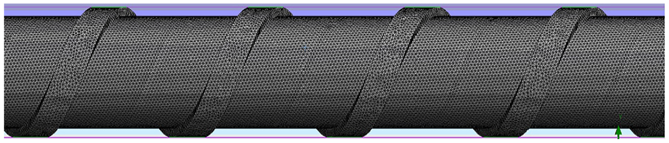
Mesh generation of the drill rod.
Static analysis on the drill rod aims to obtain the effect of the constant load on the drill rod when no inertia and damp is taken into account, and its dynamic formula with the classical mechanics theory is shown in equation (1). Among that [M], [C], [K], {x}, and {F} denote mass matrix, damp matrix, stiffness coefficient matrix, displacement vector, and force vector, respectively.

During the process of static analysis, the force is independent of time variation; thus, equation (1) can be simplified as the formula

Loads and constraint condition exerted on the drill rod.
As for the loads, the inertia load is set as 9.8 m/s2 due to the weight of the drill rod. The force loads are exerted with the feeding force F1 and the rotation torque M2, and they are set as 102 kN and 3500 N.m, respectively. As for the constraint condition, a fixed constraint is exerted at the end of the drill rod closing to the drill bit based on the actual working conditions. After the loads and constraint condition are exerted, the model can be solved with ANSYS Workbench, and the cloud map of the static analysis is shown in Figure 7.
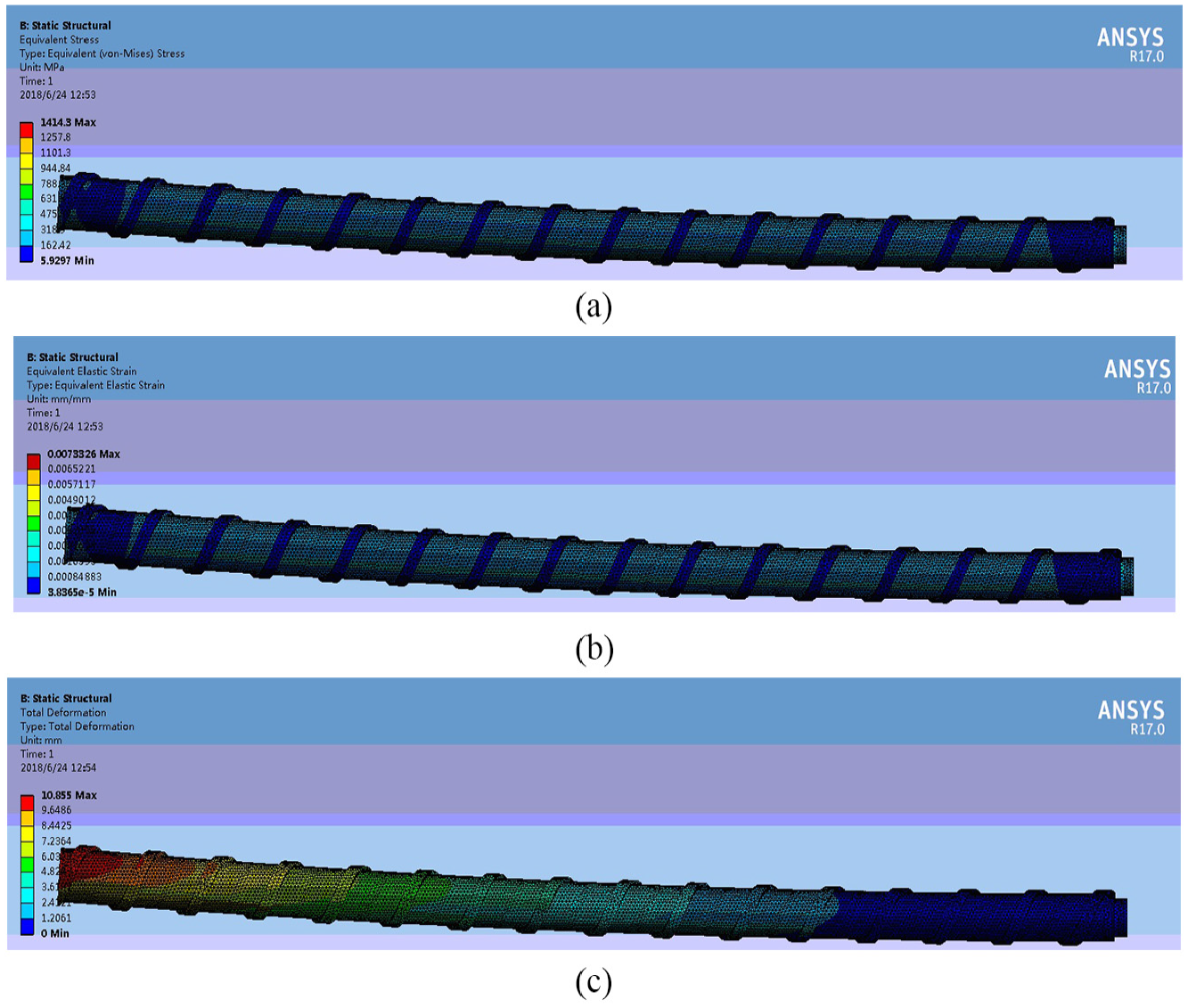
Cloud map of the static analysis on the drill rod: (a) stress, (b) strain, and (c) deformation.
Moreover, the static analysis results on the drill rod are shown in Table 2.
Static analysis results on the drill rod.

According to the analysis results, the maximum stress is generated on the top of the drill rod and reaches 1.4143 MPa, however much less than the allowable stress of the material DZ40, that is, 165 MPa; therefore, the strength of the drill rod meets the requirement. Besides, the maximum elastic strain is generated at the middle of the drill rod, and it is not high, that is, only 7.3326e–5 mm; therefore, the stiffness of the drill rod meets the requirement. Finally, the maximum deformation of the drill rod is 10.885 mm, which meets the requirement too.
Modal analysis on the drill rod
As an analytical approach to reflect the structural vibration, modal analysis is the basis of other dynamic analysis, thus the natural frequency, vibration mode, and vibration mode coefficient can be obtained; furthermore, resonance can be avoided with modal analysis. Based on the above theory, modal analysis on the drill rod is performed to avoid resonance during the process of drilling operation. 11 The previous six-order modal vibration modes shown in Figure 8 are extracted, and the natural frequency shown in Table 3 is analyzed.

Previous six-order modal vibration mode: (a) first-order modal vibration mode, (b) second-order modal vibration mode, (c) third-order modal vibration mode, (d) fourth-order modal vibration mode, (e) fifth-order modal vibration mode, and (f) sixth-order modal vibration mode.
Modal analysis results on the drill rod.

The critical rotation speed can be calculated with equation (2), that is, the critical rotation speed equals to 60 times natural frequency, thus the previous six-order critical rotation speeds are obtained and shown in Table 4.

Previous six-order critical rotation speeds (unit: r/min).

The rated rotation speed of the drill rod is 120 r/min according to the detection data, and it is less than the first-order critical rotation speed. Furthermore, there is a huge gap between every-order critical rotation speed and the rated rotation speed; therefore, no resonance occurs when the drilling rig works.
Analysis on simulation results
Based on the static working mechanism and dynamic working mechanism of the drill rod, the static and modal analyses on the drill rod are performed, and the model of the drill rod is verified. First, the deformation of the drill rod is only 10.885 mm according to the static analysis; moreover, the drill rod performs drilling operation stably, which proves that the model of the drill rod is built correctly. Second, the rated rotation speed of the drill rod is 120 r/min, so it should generate 2 Hz vibration frequency based on theoretical calculation, otherwise the previous six-order modal natural frequencies vary between 22.1 and 389 Hz, which is more than the natural frequency of the drill rod; therefore, no resonance occurs.
Hydraulic control for the drilling rig
Load-sensing hydraulic system
Classical closed hydraulic loop consists of a variable displacement pump and a hydraulic motor (or hydraulic cylinder). The motor is directly driven by the pump, and the oil from the motor outlet is directly delivered to the pump inlet, thus its rotation speed and rotation direction can be adjusted by the variable displacement mechanism of the pump. Load-sensing system provides with necessary hydraulic pressure and flow rate according to the requirement of the loads.12,13 As for the load-sensing closed hydraulic system, when the external loads vary, the motor receives and transfers them to the pump, thus the output flow rate is controlled via the swash plate inclination angle of variable displacement mechanism, that is, the variable displacement pump can provide with the proper flow rate according to the variable loads.
Conventional simulation on drilling rig hydraulic power
AMESim is a multi-disciplinary simulation platform adopted for the complex system modeling and simulation, and can provide with a flexible solution on fluid power, mechanical engineering, thermal fluid, and control system. And, the simulation process consists of sketch mode, sub-model mode, parameter mode, and run mode,14,15 and the sketch model of the closed hydraulic loop of the drilling rig is built and shown in Figure 9. Among that, the external load signal that the motor receives (labeled as “7”) is fed back to the comparison unit (labeled as “8”); next, an error is generated after the load signal is compared with the control signal (labeled as “6”). Finally, the pump provides with proper displacement according to the error.

Simulation model of drilling rig hydraulic power 1: variable displacement pump; 2: motor; 3: supply pump; 4: pressure regulating valve for supply pump; 5: pressure regulating valve for variable displacement pump; 6: control signal; 7: load signal; 8: comparison unit.
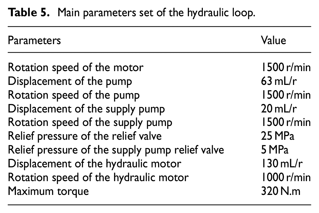
Furthermore, the parameters in the simulation model are set and shown in Table 5.
Main parameters set of the hydraulic loop.
The load labeled as “7” in Figure 9 is set to increase sharply from 0 to 320 N.m at 1 s, which is shown in Figure 10.
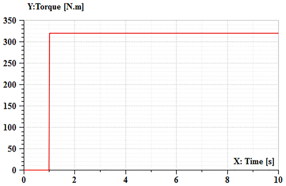
Load setting.
The control signal labeled as “6” in Figure 9 is set to be 1000 r/min to control the rotation speed, which is shown in Figure 11.

Control signal.
The simulation parameters are set as follows: the duration time and the sampling period are set to be 10 and 0.01 s, respectively. Next, simulation is started, and the simulation curve of the hydraulic motor rotation speed is shown in Figure 12. It can be found that, under the above conditions, the hydraulic motor rotation speed reaches the maximum value of 960 r/min at 1.11 s and achieves the stable value of 795 r/min at 2.64 s. It indicates that the system responds rapidly; however, the system overshoot is up to 20.7%. Besides, it takes 2.64 s for the system to become stable, and the system oscillates seriously during the period.

Curve of the hydraulic motor rotation speed.
The simulation curve of the hydraulic motor pressure is shown in Figure 13. It indicates that the system overshoot is about 25%, and it takes 2.1 s for the system to become stable.

Curve of the hydraulic motor pressure.
Similarly, the simulation curve of the hydraulic motor torque is shown in Figure 14. It indicates that the system overshoot is about 89%, and it takes 2.79 s for the system to become stable; thus, some measures are needed to be taken to decrease overshoot and vibration, and accelerate stability.

Curve of the hydraulic motor torque.
Hydraulic power controlled with fuzzy PID
PID is a control method adopted in the industrial engineering, for example, hydraulic system, and it consists of proportion unit, integration unit, and differentiation unit. 16 Besides, the hydraulic system can be simulated via joint AMESim and Simulink (a plug-in in MATLAB) to examine control algorithm performance, and the simulation models built are shown in Figures 15 and 16.

Co-simulation on AMESim model.

Co-simulation on Simulink model.
The key parameters in PID are set according to the critical proportioning method and the empirical data, and proportion Kp, integration Ki, and differentiation Kd are set to be 1.374, 1.0992, and 0.429, respectively, and the curves of the hydraulic motor rotation speed with the conventional method and PID method are shown in Figure 17. It indicates that the rotation speed overshoot and vibration with PID are both lower than the conventional method. 17 However, the response of rotation speed with PID is slower than that with conventional method, and it takes 2.75 s for the rotation speed to become stable.

Hydraulic motor rotation speed with PID and conventional method.
Similarly, the curves of the hydraulic motor pressure with the conventional method and PID method are shown in Figure 18, and it indicates that it takes nearly the same time to reach steady state; however, the system overshoot and vibration with PID are lower than the conventional method. Finally, the curves of the hydraulic motor torque with the conventional method and PID method are shown in Figure 19, and the simulation results are nearly the same with them of the hydraulic motor pressure.

Hydraulic motor pressure with PID and conventional method.

Hydraulic motor torque with PID and conventional method.
Therefore, the system overshoot and vibration obtained with PID are preferable than with the conventional method, despite the former response is slow a little.
In order to further improve response ability and complete performance, fuzzy theory is also introduced and adopted to control the hydraulic system. Furthermore, simulations on the hydraulic motor rotation speed, pressure, and torque are all performed with conventional method, PID, and fuzzy PID method.
The simulation results of hydraulic motor rotation speed with three methods are shown in Figure 20; similarly, the simulation results of hydraulic motor pressure and torque are shown in Figures 21 and 22, respectively.

Hydraulic motor rotation speed with three methods.

Hydraulic motor pressure with three methods.

Hydraulic motor torque with three methods.
Analysis on simulation results
Based on the simulation results, it indicates that the response of the hydraulic motor rotation speed obtained with fuzzy PID is the quickest among three methods, besides the overshoot and vibration obtained with fuzzy PID are the lowest too. In addition, the stable state of the hydraulic motor pressure and torque obtained with fuzzy PID is achieved in the quickest time among three methods, meanwhile the overshoot and vibration obtained with fuzzy PID are the lowest too.
Conclusion
In order to identify the essence of sticking for the drill rod adopted in underground coal mine, a comprehensive solution combing FEA and fuzzy PID on the drilling rig is proposed. Then, the static analysis and the modal analysis on the drill rod indicate that the strength and stiffness of the drill rod meet the requirement. Furthermore, the co-simulation on the drilling rig hydraulic power with AMESim and Simulink controlled with fuzzy PID is preferable than that controlled with PID and the conventional method.
Footnotes
Handling Editor: James Baldwin
Declaration of conflicting interests
The author(s) declared no potential conflicts of interest with respect to the research, authorship, and/or publication of this article.
Funding
The author(s) disclosed receipt of the following financial support for the research, authorship, and/or publication of this article: This work was supported by Open Fund from State Key Laboratory of Mine Disaster Prevention and Control Co-founded by Shandong Province and the Ministry of Science and Technology (No. MDPC201609), Open Foundation of the State Key Laboratory of Fluid Power Transmission and Mechatronic Systems (No. GZKF-201614), Project of Natural Science Foundation of Shandong Province (No. ZR2015EM042), Project of Shandong Province Higher Educational Science and Technology Program (No. J18KB020), and Tai’an City Science and Technology Development Program, China (No. 2017GX0033).