
Abstract
The unique thing about this research work is that it is the first comprehensive study out of all its kinds in Pakistan. Pakistan is an agricultural country and faces dearth of water resources availability for crops. This research work is very inevitable because it fulfils the water needs and also helps to minimize the energy deficit. This research article represents the means of wind speed data collection, design of wind-driven water pumping system and analysis of the design under different wind conditions in Pakistan. Wind speed data for province Punjab and Sindh are collected from Global Wind Atlas, Pakistan Meteorological Department and World Weather Online. First, design calculations have been made on the basis of analytical methods. Then proposed design is analysed using ANSYS Fluent Simulation models. Wind energy input, lift and drag on blades, rotor power output transmitted to the pump and water discharge from the pump have been calculated and verified from the simulation results. It has been shown that for any rotor size windmill produces maximum power output when angle between blade chord and axis of blade rotation is in the range of 23°–27°. Recommended height of windmill tower for 8–12 ft rotor diameter is 35–50 ft. Designed wind pump system can lift the ground water from 50 ft depth and discharge depends upon the size of windmill used. From the outcomes of the analysis, different designs having different power output and water pumping capacity have been proposed for different operating and wind conditions in the country.
Introduction
With an increase in prices of the fossil fuels, world has been focusing on the new means of renewable clean energy which is cheaper and environmentally friendly. Wind energy is one of the most important types of renewable energy. In ancient days back to 3500 BC, wind energy was used to produce aerodynamic push to meet very low energy demands to drive boats. 1 As the years passed, there were observed some innovations and modifications in design resulting from more energy needs. First windmill was developed in China and it was a vertical axis windmill having long curved metal strips as blades. Windmill rotor was connected to a large pulley having many small water buckets mounted over a rope.
Renewable energy has always been a key research area for many researchers because of continuously increasing energy demands. Recent development and technologies in the field of renewable energy harnessing has positive impact on public health and environment. World energy requirement is anticipated to increase about 15% from 2012 to 2020. 1 Horizontal axis wind turbine was introduced in Northern Europe in middle ages. It was a modified design using a hub and blades called sails. Design also used shaft and gears for power transmission and conversion of rotary motion into reciprocating. At first, it was used to grind gains and cutting of timber.
Revolution in the design took place in the United States when more efficient windmill was developed using previous research work. The purpose of the windmill was to lift the ground water for irrigation, drinking water for livestock, store surface water in elevated tank and drainage of the rain water in flood seasons. There were a lot of significant improvements in the design, that is, self yawing mechanism to ensure that rotor always faces the wind direction, optimum lift and drag coefficients, safety against damage in high winds or storms, efficient power transmission mechanism, developed materials and durability, etc. These windmills were manufactured commercially, and technology was adopted my different countries like Australia, South Africa and Argentina and other around the world where wind potential was significant. In all these countries, windmills were used to meet the water requirements when there had been scarcity of water during summer seasons. Thus, this technology played a very important role in economic development of these countries. During 1950s, there has been a decline of this technology due to innovations in the field of engines and methods to use the fuels efficiently. Now world is moving again towards the green energy owing to fact of high fossil fuels costs, limited availability and severe climate impacts. In rural areas of developing countries like Africa, Kenya and Nigeria, wind pumps have been used to fulfil water requirements.
A series of multi-bladed windmill designs for irrigation purpose was developed in the United States in the 19th century. Later on, horizontal axis windmills were used for electricity as well. With increasing benefits from the technology, more research work was conducted which resulted in an up-to-date design. Design of windmill is effective in those locations where wind speed ranges from low to moderate. For high wind speed locations, aerofoil design of the blades is used and such type of wind turbines is used for electricity production. This technology has helped in reducing the emission and dependence on non-renewable energy.
All the components and working of the wind pump are shown in Figure 1. Windmill is a multi-bladed rotor which is mounted on a hub. There may be 8, 16, 18 and 24 blades depending upon the wind parameters and design. Multiple blades in the form of curved blades (sails) are rigidly mounted at some angle to the wind direction. Curved shape of blades helps to harness more energy when air passes over the sail of the blades. When all the blades are mounted over the hub, they form the rotor. When wind passes through the rotor, it rotates to produce the mechanical energy. Rotor is connected to a shaft which tends to rotate the gears. Transmission system consists of gears, guide wheel, pitman arm and guide shaft. Pump rod passing through transfer the motion to the pump plunger. Tower is a high strong support holding windmill and gear mechanism. Tower must be high enough to surpass the top of nearby trees and buildings to avoid any obstruction in wind path approaching the windmill.

Components and working of a wind pump.
The practice of traditional windmills for lifting water was introduced in Holland from the start of 15th century onwards. The well-known Dutch windmill had been used for water drainage like drainage of swamplands and lakes to reclaim new lands for different purposes. It was then adapted to other applications such as water supply to storage tanks and irrigation. 2 Now wind pumps are used globally for different purposes. Smulders 3 showed wind pumping can find its place in different pumping technologies, for example, hand pumps, solar and engine-driven pumps.
Applications such as water supply to small communities, cattle watering and small-scale irrigation require little power usually, typically ranging from 10 to 250 W of hydrodynamic power output uninterruptedly. There are plenty of regions around the world with enough wind power resources for wind pumping as moderate wind speeds suffice the purpose.
Water is a primary need of mankind as it is equally important and used for all types of domestic uses, life on earth and sea, and for cultivation of crops. So there is need in most of the rural areas where water should be lifted from the ground depth or from river and ponds to supply for the crops. Though scope of using wind for irrigation purposes is old, its importance in field of renewable energies can never be underestimated. Ultimately such kind of mechanism is required which can lift water from ground using wing energy. 2
US National Renewable Energy Laboratory (NREL) has developed geographical wind map in Pakistan and suggested the utilization of unexploited wind energy in the country. Pakistan has a wind potential of 346 GW. 1 The city of Hyderabad and Karachi along with the streak of coastal area are the potential locations where this kind of systems can operate efficiently. Moreover, southwestern Pakistan is rich in wind resources. 4 Atlas 5 shows the wind map data of Pakistan, and these potential areas are expected to play a very vital role in fulfilling future energy requirement of the country.
In rural areas, wind energy resource is sufficient enough that it can be used to operate the wind pump system and have potential to replace energy production from fuels as they have high cost and large emissions, thus securing the environment and future. Wind is the most important and prominent type of renewable energy. It is available in all locations due to different temperature zones and resulting pressure variation on different locations. 6 La Rotta and Pinilla 7 investigated the commercial positive displacement pump for wind-water pumping and the evaluated pump performance in terms of its overall and volumetric efficiencies.
The technological advancements starting in early 1900s in the field of hydro energy systems had bought an innovative change world’s energy productions. Recently, this kind of systems has become very efficient due to use of highly consistent equipment and many researcher and engineers believe that they will overcome most of the energy demand with their overwhelming outcomes. These systems have gained enough capacity to store energy in the form of potential energy of water. 8
Díaz-Méndez et al. 9 used a very simple methodology and made a comparison between different renewable technologies in term of effectiveness, cost, reliability, energy production and installation at particular location. Some non-renewable energy sources were also discussed to make comparison fairer. In all the systems, the main idea was to supply water for irrigation. For this purpose, they chose three different locations in Cuba, Spain and Pakistan because all these three countries have different environment, coordinates and geographical backgrounds. The investigation took into account wind resources and availability at locations, power capacity, distance to the grid, seasonality, water storage tank volume requirements and dates of plantation. Comparison was made in terms of cost estimation and energy associated with each system. The locations where no grid connection is available, the distance to the grid and the wind resource available are key factors to be taken into attention while deciding among available options. Finally, it was also showed that the water elevation has a major impact on the economic feasibility of wind pump technology as compared with that of solar radiations on solar photovoltaic pumping technology. The results revealed that usually the critical factors to be considered while making energy management decisions differ country to country. In Spain, the closeness of the electrical grid to wind station makes it the best option. Similarly in Pakistan, limited wind resources are a there, but they can be harnessed and water need can be met by installing wind pumps.
Cruz et al. 10 used an integrated approach to find scheduling and the optimal operation of a wind-powered water pumping system. In his approach, he performed the modelling the technical operational limitations of system and diminished the effect of variations in wind parameters on the active power output of the wind energy resource. He also showed that a mixed-integer linear optimization-based approach should be used to maximize cost effectiveness and sustainability of the system. 10
Peillón et al. 11 used a methodology and estimated balance between water availability and water needs to evaluate the feasibility of the windmill-based irrigation system. To meet the purpose, they include several factors like daily 3-hourly wind speed, greenhouse evapotranspiration as a function of planting date of crops. Flow supplied by the wind pump was considered as a function of the elevation height or lift. Windmill had 2.2 m diameter with eight blades and it required wind velocity of 2.77 m/s to start. The system was designed to operate between range of 2.77 and 10.8 m/s. Wind pump had a tower 6 m high tower with a triangular section whose cross section area decreases gradually towards top. Harries 12 also proposed that generation of electricity using wind energy needs wind speed more than 5 m/s to rotate the turbine but for wind pumps lower wind speeds can be sufficient because most of the wind pumps can operate at wind speed of 3 m/s and will start furling at speed of about 12–15 m/s.
Ayodele et al. 13 conducted a comprehensive study of this system. They used 16 years’ daily average wind speed data obtained from Nigeria Meteorological Agency (NIMET) Oshodi, Lagos. The results he obtained showed that the wind power densities of the two different areas range from 165 to 207 W/m2 and it was sufficient to provide energy for the water needs between 1900 m3/day to 2300 m3/day for these areas. The wind speed of these regions was found to be 2.7 m/s and 9 m/s, respectively. He suggested the use of Goulds model submersible pumps in the range of 30–50 hp for meeting the water requirements.
Rehman and Sahin 14 conducted their research in Saudi Arabia with a purpose to provide water using wind energy to remotely located areas which did not have any electricity facility. Small windmills of order 1–10 kW were selected combination with Goulds 45 J water pump model. Pump used the energy from wind and pumped water to locations like Rawdat Ben Habbas, Arar and Juaymah in Saudi Arabia. Odesola and Adinoyi 15 also tested wind pump setup at wind speed of 1.45, 1.80 and 2.10 m/s with a water discharge rate of 6.61, 6.78 and 7.81 L/min, respectively.
Computational fluid dynamics (CFD) is one of the powerful tools for blade shape analysis of wind machines. Investigation of the system can create an opportunity for research into CFD methods that definitely allows engineers to simulate complete turbines at realistic conditions. There is a huge scope for refining the wind-water pumping system with various combinations of number of designs and using different materials for the fabrication of blade which have better stability, efficiency and cost-effectiveness.16–18
In Punjab, southwest region of the province including Rahimyar Khan, Bahawalpur, Bahawalnagar, Lodhran and some parts of Dera Ghazi Khan have enough potential to be used for water pumping. All these are agricultural areas and demand of water is high. Wind speed usually has some variation with respect to season so wind velocity lies in the range of 2.5–7 m/s, giving the average of 4 m/s approximately. Figure 2 shows the wind map of Pakistan provided by Pakistan Meteorological Department (PMD).

Wind map of Pakistan. 4
Recently, Wind Power Potential organization conducted surveys of coastal areas including Sindh coast and southwest belt of Punjab province of the country with help of PMD and indicated the existence of a potential for harvesting wind energy using currently available modern technologies.
Methodology and data collection
Method to conduct this research can be divided into following steps (Figure 3).
Comprehensive study of wind pump, its operation and background
Determine the suitable geographical locations in the country having sufficient wind potential and wind parameters from Alternative Energy Development Board (AEDB), Global Wind Atlas (GWA) and PMD
Estimation of power requirements and capacity of water pump and calculations of blades size, rotor diameter and swept area, tower height and gear box specifications accordingly
Measure the characteristics of windmill, that is, power and torque using analytical approach
Design and analysis of wind pump model using Solid Edge and ANSYS
Derivation of results and conclusion

Schematic of methodology.
Theoretical study involves a deep investigation of working operation of wind pump and current designs used in the world. The design process starts off with analysis of the existing windmill designs and their respective operating condition. This formed a rough idea of the eventual windmill design that would be modified to the Pakistan regions. In order to achieve the optimum design characteristics such as torque and power produced by the windmill, various calculations and structural analysis would be done as well. Thus, design modifications of windmill and pumping system to meet geographical wind conditions in Pakistan are main target. Calculations and results thus obtained using analytical methods would be used in Solid Edge to develop a model and validation of results using ANSYS.
Wind speed data are collected from GWA, PMD and World Weather Online, and data are organized for different cities of province Punjab and Sindh in Pakistan. It is very important to evaluate the wind velocity values of the desired regions in order to design a wind pumping system. In this research study, we investigated the wind conditions in Pakistan especially southeast belt of Punjab and suburb regions in Sindh province. All these areas have enough wind availability per day and large reserves of underground water. Being an agriculture region, wind powered pump finds its large applications in this area.
Wind speed data of some selected cities are presented on monthly average basis and yearly average for a particular year in Table 1 and Figures 4 and 5.
Month-averaged wind speed data for different cities of province Punjab and Sindh, Pakistan. 19

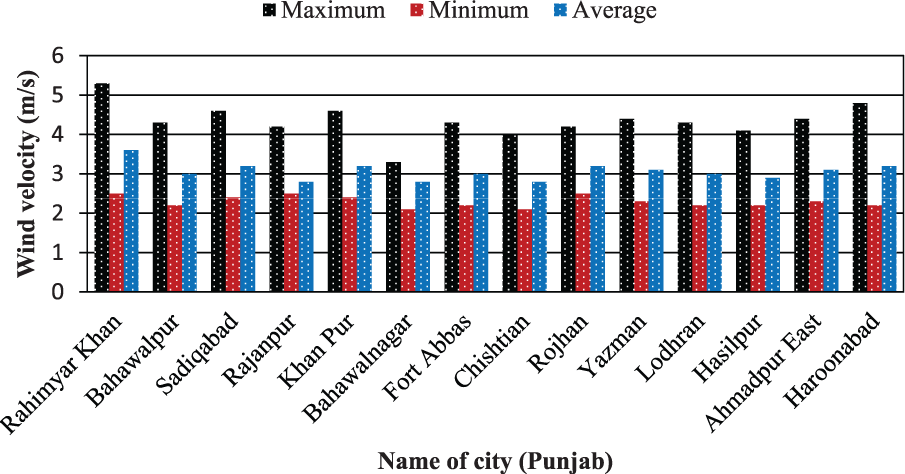
Representation of wind speed data of cities in Punjab.

Representation of wind speed data of cities in Sindh.
Wind speed is never constant all the time; instead, it varies in different time of the day. In this study, two different wind speed distribution methods have been applied to find out the average wind speed for a particular city.
Weibull distribution method
According to Weibull, wind speed distribution is governed by the following equation 20

Value of Weibull shape factor K lies between 1 and 3. The area which has very low variations in wind velocity has higher value of K. When there are considerable variations in wind velocity data, value of K is closer to 1. Both Weibull scale parameter
Similarly, annual wind energy in kilo watt hour available per unit area is given by

Gamma function
Meteorological distribution method
Meteorological distribution method states that occurrence frequency of wind velocity is mainly the function of cumulative frequency of wind velocity during a particular interval to time. Smaller the interval, greater would be the credibility of wind velocity value distribution. Knowing the wind velocity cumulative frequencies, occurrence frequency can be given by 20


Applying the statistical techniques on available wind speed data gives us close prediction of wind speed and wind energy data. Vf, Ve and Vm are most frequent, energetic and simple mean velocities, respectively, as shown in Figures 6 and 7.

Wind speed and annual wind energy prediction using Weibull and meteorological distribution methods – Punjab.

Wind speed and annual wind energy prediction using Weibull and meteorological distribution methods – Sindh.
Design of wind pump
It is very important to evaluate the wind velocity values of the desired regions in order to design a wind pumping system. In this research study, we investigated the wind conditions in Pakistan, especially southeast belt of Punjab and suburb regions in Sindh province. All these areas have enough wind availability per day and large reserves of underground water. Being an agriculture region, wind-powered pump finds its large applications in this area.
Wind speed data of some selected cities are presented on monthly average basis and yearly average for a particular year in Table 1.
Basic design requirements
Following are the basics requirements for a windmill design used for water pumping:
High torque, T
High solidity, σ
Relatively low tip speed ratio λ, low rpm ω
To drive a reciprocating water pump, high torque is the basic requirement. Multi-bladed windmills have high solidity and low tip speed ratio which results in higher starting torque. There are two choices to set our target:
Set the desired output of the system and specify all parameter in accordance
Analyse how much wind energy is available at the rotor at specific location and what output can be attained while considering all impracticalities and losses
Keeping in view all wind parameters pertinent to Pakistan, it is desirable to go for later choice. Taking different possible value to wind velocity, various wind pump design specification will be proposed. Schematic of the major components involved in the system is shown in Figure 8. Design specifications for all these components are proposed below.

Components of the wind pump under design considerations.
Wind energy calculations
Wind velocity of selected regions in Pakistan lies in the range of 2.5–5 m/s. For model development, mean wind speed of 3.5 m/s is considered

From chart,20,21 suitable diameter of windmill for given wind velocity is 3 m. Taking windmill diameter as 3 m and 3.5 m/s of wind speed, corresponding values of Pw have been calculated which equals 109 W.
Consideration of losses in system
Wind wheel losses
As per law of inertia, a body will come to rest when some external force is applied to it. In this case, external force is mainly due to aerodynamic friction which gradually stops the wheel or tends to stop it. A well-balanced and efficiently designed wind wheel will have an efficiency value of 60%. If this value is required to increase or frictional losses are desired to decrease, then surface area of the wheel must be reduced to offer less friction. But doing this will decrease the amount of energy acquired from the wind and much of wind will pass through the wheel unused. It is undesirable. Less parts and light-weight design structure increase the efficiency, but there are also some restrictions regarding design failure and materials strength. So the optimum value of wind wheel efficiency is taken to be 60%.
Bearing and gears
Bearing and gears are normally most efficient part of the system, but there are some losses associated with them. Babbitt metal which is durable, less wear and has decreased energy losses is used for manufacturing of bearing. Gears with excellent design and very fine finished surface can have 97% efficiency per mating pair. Amount of energy lost is also dependent on load applied on the wheel. Well-balanced gear set increases the life of system and cause fewer vibrations, and provides leverage to the system to operate under low wind and pump water at high head. Overall efficiency of the bearing and gears system is taken to be 95%.
Fluid friction losses
Whenever a fluid passes through a pipe or duct, frictional loss is accompanied with it which is given by Darcy formula

f is Darcy factor and depends upon diameter and velocity of the fluid. In the above expression, we can see that friction losses are mainly dependent on fluid velocity and hydraulic diameter of pipe. Fortunately in our case, fluid velocity is quite low and hydraulic diameter is large enough to minimize the losses. Thus, by using smooth pipe with enough size, good values selection and avoiding sharp bends will make the efficiency up to 95%.
Losses in pump
Pump is the most important part of the system which must be considered while estimating the system losses. Nowadays, pump cylinder made of bronze or brass tubing having polished bore and leather seals are considered more efficient.20,21 This design has long life and very less leakage over times. But frictional loses in the pump are very significant. Thus, with best design and excellent material, overall efficiency of the pump is taken to be 75%.
For designing purpose, it is required that pump should lift water to 50 ft height. Thus, mechanical power available to for pump is calculated as

Thus, power delivered to pump after considering all above losses is estimated to be 44.26 W. With every design there are some uncertainties associated with the system. So we incorporate all these uncertainties so that system may work even for minimum fluctuating value of power delivered. So to ensure the minimum possible output, consider 20% unaccountable losses due to different natural uncontrolled phenomenon; we get power 37 W available for pumping. Figure 9 shows distribution of total wind energy taken by different components due to limitations, losses and useful work.
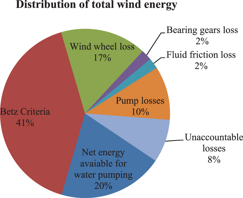
Distribution of total wind energy.
Water capacity
Flow rate from the pump is calculated as

So using theoretical knowledge we determine that a windmill having 3 m (10 ft) diameter operating under wind velocity of 3.5 m/s can lift about 250 gallon of water per hour from a depth of 15 m (50 ft).
Blade design consideration
It is the most important parameter to be considered while designing a windmill blade because almost all the other parameters like configuration, rpm and torque depend upon it. Tip speed ratio λ gives the relationship between blade tip velocity ω and actual wind speed V

Table 2 shows the different considerations regarding selection of suitable tip speed ratio.
Tip speed ratio and design parameters.

If the tip speed is high, low chord length is required which definitely reduces the blade dimensions and material used. But higher tip speed ratio increases the aerodynamic and centrifugal frictional loss. To reach some conclusion, we have to fix some parameters like rotor size and number of blades, and evaluate the performance.
A windmill operating a reciprocating piston pump for water supply requires high torque. Rotational speed is not very crucial for such applications. High torque requirement suggests that lower value of tip speed ratio must be selected to meet the purpose.
Threshold tip speed ratio is given by


Using the above-mentioned known values, area of each blade is estimated to be 3.77 ft2 (0.35 m2).
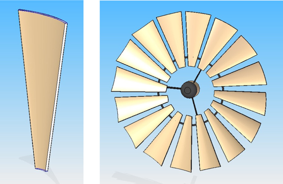
Blade and rotor designed on Solid Edge.
Solidity σ ranges between 0 and 1. For a windmill used for water pumping, value of solidity is high to achieve high starting torque. For that purpose, condition of σ = 0.8 must be met for the smooth operation of the system. 22 Value of solidity obtained for this design is well above the threshold limit for water pumping windmills.
Windmill characteristics
Actual torque produced by wind force at the rotor is given by
Torque coefficient is the ratio of actual toque transmitted to pump and theoretical torque produced. For multi-bladed high solidity windmill its values is 0.24 (Figure 11(a)). It is important to calculate and relate the power coefficient of the design whose standard value ranges from 0.30 to 0.40 (Figure 11(b)). For this design, power coefficient equals 0.35 which is comparable with the standard range.

Dimensionless (a) torque-speed and (b) power-speed characteristic of wind rotors of mechanical wind pump. 22
Different design of rotor behaves differently under specific wind conditions. Modern rotors are designed to convert wind energy into mechanical work for electricity generation. Thus, they are designed to possess high tip speed ratio. Under low tip speed scenario, they do not perform well and have low value of power and torque coefficient. Contrarily, classic rotors are designed to operate under low wind conditions and have low value of tip speed ratio. It enables the classic rotor to possess high value of power and torque coefficient which is the basic requirement of a wind pump to operate as shown in Figure 11(a) and (b).
Power transmission
Power extracted from the wind through rotor is transmitted to the pump with the help of a shaft, gears, bearings and pump rod. All the mentioned components constitute the power transmission mechanism. Design of gearbox and gear ratio used must match the pump size and number of strokes per hour to meet the desired water output.
In windmill power transmission system, gear box has two pairs of meshing gears which transmit the power to pump rod with the help of Pitman Arm. When the wind energy rotates the rotor, shaft rotates the pinion which ultimately drives the larger gear. Pitman Arm pivoted to the gear converts the rotary motion into reciprocating motion of guide wheel which moves up and down in pump rod guide. Pump rod connected to the centre of guide wheel thus moves up and down. This up and down movement constitutes the stroke of the piston of pump. Gears used in water pumping windmills are usually low velocity external spur gears which have teeth parallel to axis of the gear rotation.
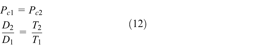
As mentioned earlier, high torque is required for smooth operation of water pumping system. Therefore, gear ratio of 3/2 is used to increase the torque. Now consider D1 and D2 be the diameter of driver (pinion) and driven gear, respectively. Gear ration is given by the equation

Diameter of pinion is calculated to be 3.15 in. (8 cm) which is also called pitch circle diameter.
Angle between common tangent at pitch point and common normal at the point of contact of two gears is called pressure angle. Standard values of pressure angle are 14½° and 20°. 23 Here value of 20° is used. For two meshing gears, value of circular pitch or module must be same, so
With the gear ratio of 3/2, number of teeth on gear and pinion are 24 and 16, respectively. With all the basic design parameters calculated above, KHK Gears allows creating a complete gears design and simulating the results. Figure 12 shows the interface of KHK Gears designing software. 21 All the basic input data are provided to get gear specification like size, strength, force acting on gears and tooth form coordinates. Figure 13 shows the two meshing gears’ design.

Designing of gears using KHK Gears designing software. 23

Two meshing gears, large gear and pinion have 24 and 16 teeth, respectively.
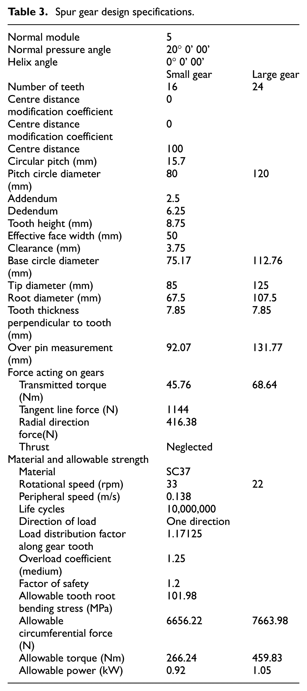
Table 3 shows the design specifications of the spur gears used in wind-driven water pumping system.
Spur gear design specifications.
Pump design
Selection of pump size is made on the basis of flow rate requirement and rotational speed driven to meet the desired output.
Water discharge per stroke is calculated as

Number of strokes in 1 min equals to rpm of driven gear so pump size be such that 22 strokes must deliver 0.015 m3 per minute

Referring standards, 24 it is desirable to use 100 mm pump for the desired discharge. Minimum stroke length is calculated as

It is important to note that stoke length can never be less than
Simulation setup of the design
Simulation of the designed rotor has been done using ANSYS Fluent 14.0 by importing the model from Solid Edge.igs file. First, the 3D computational domain is defined for single blade. Name selections are created and mesh is generated. Default mesh is refined using Global Mess Control which applies settings to whole mess altogether (Figure 14). Mesh number for this simulation is 50/inch with more than 107 cells. To make the results more precise, double precision method is used. For solution, K-omega SST equation is chosen for viscous laminar model. After setting materials, boundary conditions, solution method, monitors, and so forth, calculations are run.

Meshing of a single blade domain.
Mesh independence test
Mesh independence or sensitivity analysis is carried out to apply suitable mesh control to the computation domain. Five different mesh controls with cells ranging between 9×10⁶ and 1.4×10⁷ have been applied to the domain. Results show that values become stable, and very insignificant variation occurs when mesh number exceeds 107 (Figure 15).

Mesh independence test.
Validation of Simulation results
Historical data validation (HDV) method is used to validate the results of the simulation. A number of similar design analysis and optimization has been done experimentally in literature.10,12,15,17,20,24 Results obtained in this research work are comparable with peers’ work conducted previously.
Results and discussions
Optimization of angle of attack
Simulation of one blade to find out the optimum value of angle of attack is shown in Figure 16. Maximum value of coefficient of lift is obtained at 19° angle of attack (α) as shown in Figure 17. But at this value of α, coefficient of drag also become significant and has value of 0.18. So such value of α must be chosen at which lift and drag values are comparative so that tangential and axial force acting on a blade are maximum and minimum, respectively.

Simulation of one blade to find out the optimum value of angle of attack.

Representation of coefficient of lift and drag for different values of angle of attack.
To find out the most suitable value of angle of attack (α), its different values ranging between 8° and 20° have been used to calculate corresponding values of lift force
where

Different orientations of blade with plane of rotation.
Effect of angle between blade’s chord and relative wind speed on lift force and power output
Tangential component of the lift force is responsible for the rotation of blade about the axis of rotor. Angle between the chord of blade and plane of rotation is very important to consider because it affects the power out of the windmill.
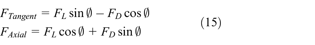
From Table 4, it is obvious that α = 10°–13° gives the best trade-off between tangential and axial forces. Increasing α beyond 13° decreases the tangential force and increases the drag effect on the curvature of the blade.
Results of simulations for different values of angle of attack.
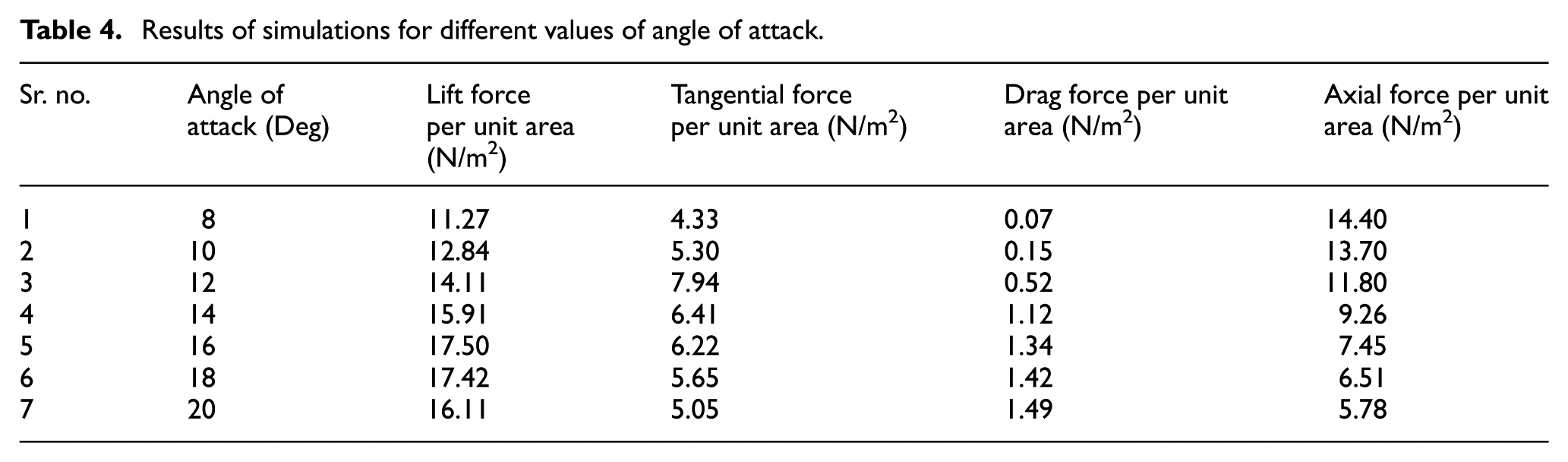
Figure 19 shows that when the angle between the chord of blade and plane of rotation is 25°–28°, power produced from the windmill is the maximum. Values of angle below or above this range decrease the power output due to corresponding decrease in lift force.

Effect of angle of attack on lift force and power output.
Steady states streamline velocity profile
Analysis shows that velocity of the streams which come into contact with the blade differs along the length of the blade (Figure 20). Velocity is the maximum at the tip of the blades and decrease gradually towards the side near hub. But at the bottom tip of the blade, velocity is slightly high due to sharp curvature of the blade. We can see that velocity of the stream at the tip reaches about 6.2 m/s and the interior regions have velocity in the range of 3.5–4.5 m/s.

Simulation of full rotor having optimum angle of blades.
Wind speed, mechanical power and water discharge
As the relation
Effect of wind speed on mechanical power and water discharge.

GPH: Gallons per hour.
Wind speed, mechanical power and water discharge.
Seasonal variations and performance
Performance of the wind pump system is greatly affected by variations in wind velocity in different months of a year. Fortunately in selected regions in Pakistan, wind blows with sufficiently high speed in the months in which water consumption is high due to increased summer temperature. To estimate the seasonal variations in the performance of wind pump due to variations in the wind speed, monthly average data of all the selected cities in Punjab and Sindh provinces are collected. Performance can be evaluated by considering power from wind, mechanical power delivered to pump and water discharge for a specific wind pump design. As different locations have different wind speed data, wind pump will perform differently in these locations. Estimation of wind energy, power delivered to pump and water discharge are the main parameters to be considered in this study, so performance of a wind pump can be characterized by calculating all these factors. Once the wind speed data are available for a particular location, all the parameters mentioned previously can be determined (Figure 21).
It is obvious from Figures 22 and 23 that 6 months (April–September) have higher wind speed, thus ultimately increased water discharge. This period is summer season and water requirement for crops is high. Thus, it is blessing from the nature that both water availability and demand are matched in this season.

Effect of seasonal variation in wind speed on performance of the wind pump system – Punjab.

Effect of seasonal variation in wind speed on performance of the wind pump system – Sindh.
Conclusions
Wind speed data in different cities are evaluated and wind pump is designed for Pakistani wind conditions. Following conclusions have been made.
Southwest regions in Punjab and the most of the cities in Sindh have sufficient wind potential (wind speed ranging from 2.5–5 m/s) that can be used for water pumping.
Wind pump can perform well under low wind speed and estimation of seasonal variations on performance showed that when water demand is high, wind speed is also high enough to match the requirements.
For wind speed of 3.5 m/s, windmill having 10 ft diameter can deliver about 250 GPH of water for use in irrigation, livestock and domestic purpose.
Analysis of the designed model in ANSYS Fluent augmented the theoretical results and design is validated.
Blades with different design and dimensions have been tested, and the most suitable design is curved blade with uniformly variable width having 16 in. and 6 in. chord length at the top and bottom, respectively. Including angle for both curved ends is 45°, and the radial length of each blade mounted on hub is 4 ft.
Power and torque coefficient of the windmill comes out to be 0.35 and 0.24, respectively, which are comparable with standard values for a multi-bladed windmill.
Wind speed is not constant over a period of time. Keeping the windmill rotor diameter same, that is, 10 ft, wind speed of 2.5, 3.0, 3.5, 4.0, 4.5 and 5.0 m/s can deliver 86, 150, 250, 355, 507 and 694 GPH of water, respectively.
This research work has revealed that there are multiple suitable locations in the country where this system can be installed. Wind pumps not only save the environment by limiting the use of fossil fuels but also meet the water needs at both commercial and domestic levels. More technological innovations and automation in the field of wind powered water pumping can lead to more efficient and reliable system.
Footnotes
Appendix 1
Acknowledgements
We thank all the colleagues whose help has been a source of light for us.
Handling Editor: James Baldwin
Declaration of conflicting interests
The author(s) declared no potential conflicts of interest with respect to the research, authorship, and/or publication of this article.
Funding
The author(s) received no financial support for the research, authorship, and/or publication of this article