
Abstract
In this article, a novel fully compliant spherical four-bar mechanism is introduced and its generalized design methodology is proposed. The original fully compliant mechanism lies on a plane at the free position (undeflected position); therefore, it has the advantages of ease of manufacturing, minimized parts, and no backlash. First, the mobility conditions of the mechanism are obtained. The dimensions of the mechanism are optimally calculated for maximum output rotation, while keeping the deflection of flexural hinges at an acceptable range. Using an optimization method, design tables are prepared to display the relationship between arc lengths and corresponding deflections of flexural hinges. Input–output torque relationship and stresses at compliant segments are obtained analytically. A mechanism dimensioned by this novel design method is analyzed by a finite element analysis method, and the analytical results are verified. Finally, the mechanism is manufactured and it is ensured that the deflections of the compliant segments are consistent with the theoretical results.
Introduction
The moving links of spherical mechanisms are constrained to the concentric surfaces of a sphere, and therefore, they generate three-dimensional movements. 1 Spherical four-bar linkages are the simplest and most compact mechanism that generates spatial motion. Spherical linkages have numerous applications such as generating functions and motions 2 or accomplishing specified spatial reorientations of an object. 3 They can be employed as grippers 4 or wrists 5 in applications such as robotic surgery. 6 Spherical mechanisms are employed to establish orientations in aerospace 7 and to simulate flapping wings inspired by natural flight. 8
Structures that gain some or all of their motion through the deflection of compliant segments are defined as partially or fully compliant mechanisms, respectively. Fully compliant mechanisms possess no friction-based classical joints in their structure. The advantages of compliant mechanisms include reduced number of parts and weight, lubrication free, low cost, and less wear, clearance, and noise. 9 The compliant segments are replaced by an equivalent system of torsional springs, joints, and links using a pseudo-rigid-body model (PRBM) technique. 9 In the literature, planar compliant mechanisms have been extensively studied.10–12 However, there are limited studies available on spatial compliant mechanisms. 13 A special case of the spherical four-bar mechanism, the compliant Cardan universal joint, was studied by the authors, and it was ensured that compliant segments are majorly exposed to normal stresses due to bending. Hence, if the output torque is not high, torsional stresses can be neglected.14,15
In the literature, there are studies on “compliant spherical mechanisms.” Bowen et al. 16 described a method for obtaining mechanisms providing motion in action origami and utilized this method for creating a classification scheme. Zhang et al. 17 analyzed a type of origami kaleidocycle-inspired symmetric multistable compliant mechanism. Jacobsen et al. 18 utilized a lamina emergent torsional joint in a spherical compliant mechanism. Bowen et al. 19 presented a position analysis of coupled spherical mechanisms found in action origami. Lusk and Howell 20 described a new micro-mechanism, namely, the spherical bistable micro-mechanism. Callegari et al. 21 described the design of a robotic wrist that can perform spherical motions. Li and Chen 22 explored spherical mechanism design from possible compliant planar linkages. Palmieri 23 performed an elasto-static analysis of a 2-degree-of-freedom (DOF)-compliant spherical parallel wrist. Rad et al. 24 introduced an analytical compliance analysis and a finite element verification of spherical flexure hinges for spatial compliant mechanisms. Rad et al. 25 studied the design and stiffness analysis of a compliant spherical chain with 3-DOFs.
To the best of our knowledge, there is only one study on “compliant spherical four-bar mechanism” in the literature. Wilding et al. 26 identified and classified possible spherical lamina emergent mechanisms (LEMs) and built origami examples.
In this article, the first robust (no plastically deformed compliant segments) “fully compliant spherical four-bar mechanism” with small length flexural hinges is introduced. A novel generalized analysis and design methodology for the fully compliant spherical four-bar mechanism is proposed. The mechanism is initially at the planar state; all segments are on parallel planes, and all compliant segments are at their undeflected positions. The planar configuration enables ease of manufacturing (all segments are made of planar materials), and as the motion is symmetric to both directions, input–output rotation can be doubled; if the input link is rotated clockwise or counterclockwise, the other movable links perform the same amount of angular motion according to the fixed link, that is, symmetry axis. The mechanism can be produced from a single block by carving out the compliant segments via computer numerical controlled milling. As an alternative, compliant segments can be sandwiched between rigid plates. Moreover, in the mass production case, it can be manufactured by plastic injection molding. Therefore, the original mechanism has the advantages of minimized parts and manufacturing tolerances, ease of manufacturing, compactness, and no joint clearance.
Design of the fully compliant spherical four-bar mechanism
The mathematical model of the fully compliant spherical four-bar mechanism is constructed using the PRBM technique. Therefore, first, the conditions satisfying the planar position are investigated for a rigid spherical four-bar mechanism. Cervantes-Sanchez and Medellin-Castillo 27 described a classification layout for spherical four-bar mechanisms.
A spherical four-bar linkage is presented in a general position in Figure 1. The output angle ϕ can be determined 27 in terms of the input angle θ

where

Spherical four-bar linkage.
According to Wilding et al.,
26
there are three classes of spherical four-bar mechanism satisfying a planar state: two of them are actually the same mechanism if the output and the input link are switched, and the other one is a cross-configuration mechanism. Length of the rigid part of a compliant link must be much greater than length of the compliant part. However, it is very hard to obtain this property with the cross configuration due to its complex shape. Therefore, the open configuration mechanism is selected for the design. According to the type synthesis of the rigid spherical four-bar linkage (Figure 2), when

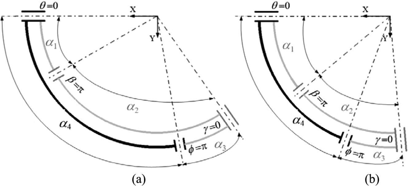
Type synthesis of the rigid spherical four-bar mechanism with different arc lengths: (a) α4 is an obtuse angle and (b) α4 is an acute angle.
Here, α1, α2, α3, and α4 are the arc length of the input link, coupler, output link, and fixed link, respectively. In Figure 2, two different simplified sketches of the selected spherical four-bar linkage type are presented for different arc lengths at the planar position. For the compliant counterpart, the values of the arc lengths must satisfy equations (1) and (2) and also the mobility conditions derived in next section. It is clear that all of the revolute joint axes must intersect at the center of the sphere. Note that the coordinate systems in Figures 1–3 are the same. At the planar state, the position variables are as follows: θ = 0, β = 180°, γ = 0, and ϕ = 180°, as shown in Figures 2 and 3.
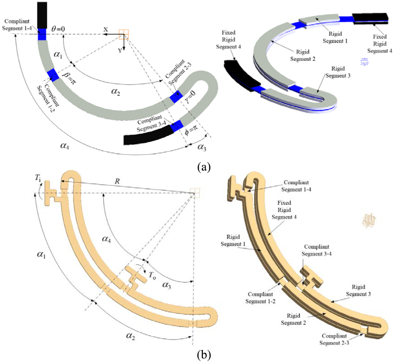
Designs of the original fully compliant spherical four-bar mechanism where: (a) rigid segments 3 and 4 curl up outside and (b) rigid segments 3 and 4 curl up inside and there are extensions on rigid segments 1 and 3.
According to the selected type of rigid spherical four-bar mechanism, two novel compliant counterparts are designed using a rigid-body replacement synthesis technique, as shown in Figure 3. The revolute joints are replaced by single-axis flexural hinges at the compliant counterparts. The axes of the compliant segments must intersect at the center of the sphere, as displayed in Figure 3. The flexural hinge between the ground (rigid segment 4) and rigid segment 1 is compliant segment 1-4. The flexural hinge between the ground and rigid segment 3 is compliant segment 3-4. The flexural hinges between rigid segments 1-2 and between rigid segments 2-3 are compliant segment 1-2 and compliant segment 2-3, respectively. The input is at rigid segment 1, and the output is at rigid segment 3. As shown in Figure 3, rigid segments 3 and 4 may curl up inside or outside and there may be extensions on rigid segments 1 and 3 for ease of transmission; the center of the extensions must be coincident with the center of the corresponding compliant hinges. Note that R is the radius of the outer rigid segment measured from the sphere center that defines the overall size of the mechanism.
The sandwiched mechanism in Figure 3 can be manufactured from one thin polypropylene plate inside and two thicker (rigid) polypropylene plates outside that are fastened by small screws. Alternatively, it can be manufactured from one thin blue polished spring steel inside and two thicker (rigid) steel plates outside that are fastened by small screws or by special glues for steel.
Mobility conditions of the fully compliant spherical four-bar mechanism
The arc lengths of the compliant spherical four-bar mechanism are determined using the rigid-body replacement synthesis technique, and, therefore, the mobility conditions of rigid segments and limiting conditions for the deflections of compliant segments are derived from the geometry of the rigid spherical four-bar linkage at the critical positions. 27
The mobility and limiting conditions are determined as follows. As θ = 0 at the initial position, there should be no lower limit for θ. The condition for no θmin is

The condition for nonexistence of an upper limit of θ is

If equation (4) is violated and θmax exists, the value of θmax can be determined by equation (5)

If θmax exists, the predefined input for the complaint mechanism (Δθmax) must be smaller than or equal to θmax. The relationship between β and the output angle ϕ is

At the initial position β = 180°. Therefore, there should be no upper limit for β. The condition for no βmax is

If the following condition is satisfied, no lower limit of β exists

If equation (8) is violated and βmin exists, the value of βmin can be determined as

If βmin exists, the maximum deflection of compliant segment 1-2 (Δβmax) cannot exceed 180° − βmin. The relationship between γ and θ can be determined from equation (10)

In the case of planar position γ = 0. Equation (11) must be satisfied for no lower limit of γ

If equation (12) is satisfied, then γ does not have an upper limit

If equation (12) is violated, the value of γmax can be determined by equation (13)

If γmax exists, the maximum deflection of compliant segment 2-3 (Δγmax) cannot exceed γmax.
The variable ϕ is equal 180° at the planar position. Hence, equation (14) must be satisfied for nonexistence of ϕmax

A lower limit exists for ϕ if equation (15) is violated

If lower limit exists, the value of ϕmin can be determined by equation (16)

If ϕmin exists, the maximum deflection of compliant segment 3-4 (Δϕmax) cannot exceed 180° − ϕmin.
Arc length optimization of the rigid segments
In previous sections, the conditions that satisfy the planar state of the design, mobility conditions of rigid segments, and limitations of the deflections of compliant segments are determined. It is clear that there are infinite numbers of arc length combinations that satisfy the related conditions. For the design, the input is at rigid segment 1 and the output is at rigid segment 3. It is intended to obtain the maximum output rotation corresponding to a predefined input rotation. Generally, maximizing the output stroke is advised to perform a specified task. Therefore, the objective of the optimization is to determine the maximum Δϕ corresponding to the predefined Δθ. Moreover, the deflections of the other compliant segments should be in an acceptable range. Hence, arc lengths are optimized for maximum Δϕ according to input rotations of Δθ = 5°, 10°, 15°, 20°, and 25°. Here, the maximum deflection of the remaining flexural hinges are limited to 10°, 15°, 20°, 25°, and 30° respectively. This specified set of deflections is common in numerous compliant mechanism designs. The optimum results of the arc lengths are searched between the specified values that yield feasible solutions, and the related regions are 10° ≤ α1 ≤ 70°, 10° ≤ α3 ≤ 70°, and 40° ≤ α4 ≤ 150°. Note that the value of α2 is dependent on other arc lengths, and it is determined by equation (2).
A constraint optimization routine is utilized to determine the optimum arc length values of the mechanism by maximizing the Δϕ function when there is a nonlinear inequality constraint. Therefore, the objective function is set as Δϕ, which is a function of the α1, α2, α3, and α4 variables. The lower and upper bounds of the αi variables are defined as vectors, and the nonlinear constraints are specified as another function. For the optimization process, Global Optimization Toolbox of MATLAB R2016a is utilized and GlobalSearch solver with “fmincon” function is used. The GlobalSearch uses gradient-based methods to return local and global minima. It starts “fmincon” that finds minimum of constraint nonlinear multivariable function from multiple starting points and store local and global solutions found during the search process. Note that, the aim is to maximize the Δϕ function. Minimizing –Δϕ is equivalent of maximizing Δϕ. Thus, –Δϕ function is used in the optimization routine.
Different sets of optimum results are shown in Table 1. In this way, the local optimum results can be observed and the arc lengths from different regions can also be selected. Moreover, the effect of different arc lengths on the output rotation can be visualized. Therefore, designers have several alternatives rather than the only one global optimum. Note that some results are shown in boldface in Table 1. For these results, the values of α3 are fixed to 20°, 25°, 30°, and 35°, and the other arc lengths are optimized. If the value α3 is not specified, it mostly converges to the minimum value of 10° during the optimization for a slightly larger Δϕ.
Optimization results serving as a design table.

Note that the radius of the arc measured from the sphere center that defines the overall size of the mechanism (R) is a free parameter and that can be arranged in combination with the length of the compliant segments. Therefore, a sufficient rigid segment/compliant segment ratio can be satisfied owing to the type of application. The conditions listed provide flexibility for the designers for possible applications. For these reasons, various optimization results are presented, and thus, Tables 1–7 can serve as a design table.
Optimization results for α4 = 45°.

Optimization results for α4 = 60°.

Optimization results for α4 = 75°.

Optimization results for α4 = 90°.

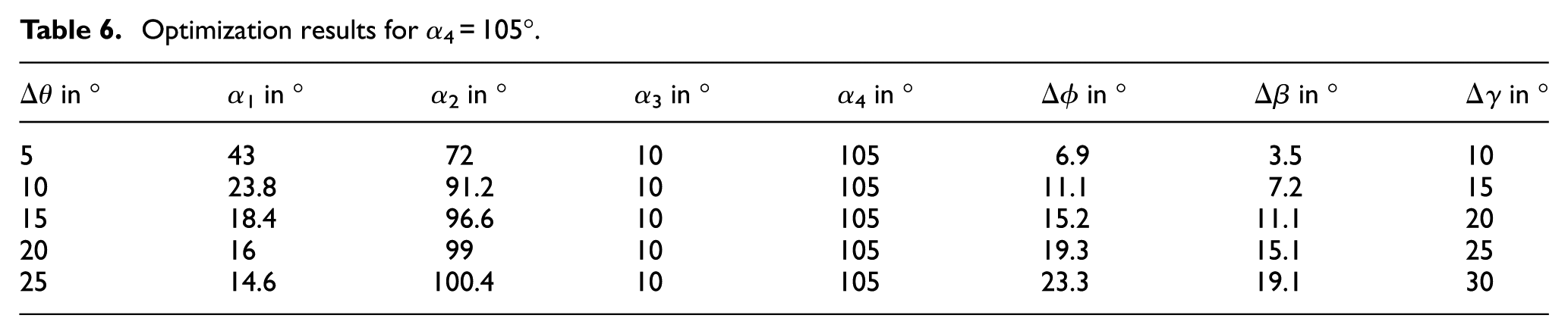
Optimization results for α4 = 105°.
Optimization results for α4 = 120°.

For the design of spherical four-bar mechanisms, generally, the axes of the input and output are predefined parameters. Therefore, generally, the arc length of the fixed link is specified. Considering this situation, we employed the same optimization procedure, but with different specific arc lengths of the fixed link. The results of the optimization for the specified values of α4 = 45°, 60°, 75°, 90°, 105°, and 120° are presented in Tables 2–7, respectively. As can be observed in Tables 2–7, α3 converges to the minimum value of 10°. Moreover, the value of Δϕ decreases as the value of α4 increases.
The optimization routine derived, the conditions listed in this section, and the results shown in Tables 1–7 can be very useful during the initial design stage of a fully compliant spherical four-bar mechanism that performs input–output motion transmission.
Input–output torque relationship and stresses at compliant segments
The PRBM technique 9 is utilized to obtain the input torque corresponding to a specified output torque, as shown in Figure 4. The aim of PRBM is to ensure a simple but accurate technique for the analysis of compliant mechanisms, even for large nonlinear deflections of flexural hinges.

Pseudo-rigid-body model of the fully compliant spherical four-bar mechanism.
As operating speeds are slow and the masses of the rigid links are negligible, a static force analysis via the virtual work method is appropriate. The virtual work performed by the active generalized forces can be derived as in equation (17)

where Ti is the input torque and To is the output torque.
The virtual work performed by the spring forces can be derived as in equation (18)

In equation (18), kij are the spring stiffness values of compliant segments i – j. The width, thickness, and length of the compliant segment of a rectangular cross section are defined as w, t, and l, respectively. Hence, the second moment of area of the flexural hinge can be obtained from equation (19)

Since the torsion can be neglected,14,15 the stiffness of the compliant segment of a rectangular cross section can be determined from equation (20)

The virtual rotation of compliant segment 3-4 can be determined as a function of θ from equation (21)

where
Similarly, the virtual angular displacements of the remaining position variables can be determined as a function of θ from equations (22) and (23)

where

where
The total virtual work done can be determined from equation (24)

Finally, the input torque Ti can be obtained for a specified output torque To from equation (25)
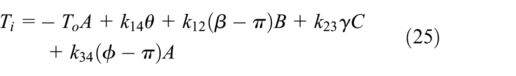
Commonly, bending is the predominant type of deflection at compliant segments, as in the case of compliant spherical four-bar mechanisms. A beam with an end moment–type loading is the main source of this deflection, if the output torque is small or zero.9,14,15 When the primary loading is an end moment type, even for the case of large deflections, the moment M can be determined from equation (26) as a function of the beam end angle 9 (the slope of the beam at its end is Θ)

The maximum stress at compliant segments with zero output torque is determined from equation (27)

Design example
First, an optimum mechanism is selected from Table 1, where the arc lengths of the mechanism are rounded without decimals as α1 = 47°, α2 = 42°, α3 = 35°, and α4 = 54°. A compliant mechanism is established using a rigid-body replacement method according to the design presented in Figures 2 and 3. Compliant segments are dimensioned as follows: the geometry of the compliant hinges is homogeneous rectangular constant cross section where thickness, t = 1 mm; width, w = 10 mm; and length, l = 12 mm. Here, length of the compliant hinge is the effective length (no fillets). A solid model of the mechanism is constructed using the CATIA® multiplatform software suite. The material is selected as polypropylene, which has a modulus of elasticity E = 1.5 GPa and a yield strength σy = 35 MPa. The position variables ϕ, β, and γ are calculated analytically from the PRBM; from equations (1), (6), and (10) for a specified input rotation θ. The deflections of the compliant segments are determined as Δθ = θ, Δϕ = 180° − ϕ, Δβ = 180° − β, and Δγ = γ, where the maximum values of deflections corresponding to an input of Δθmax = 20° are Δϕmax = 16.45°, Δβmax = 16.02°, and Δγmax = 24.9°, as shown in Figure 5. Numerous arc lengths are analyzed, and we observed that the increments of the deflections of the flexural hinges are approximately linear as in Figure 5. Note that the mechanism is initially at the undeflected position and that the motion is symmetric for both sides of the rotation. Therefore, it can be concluded that the total rotations should be multiplied by two; for example, this mechanism possesses a 32.9° (–16.45° ↔ 16.45°) output segment rotation corresponding to a 40° (–20° ↔ 20°) input segment rotation.
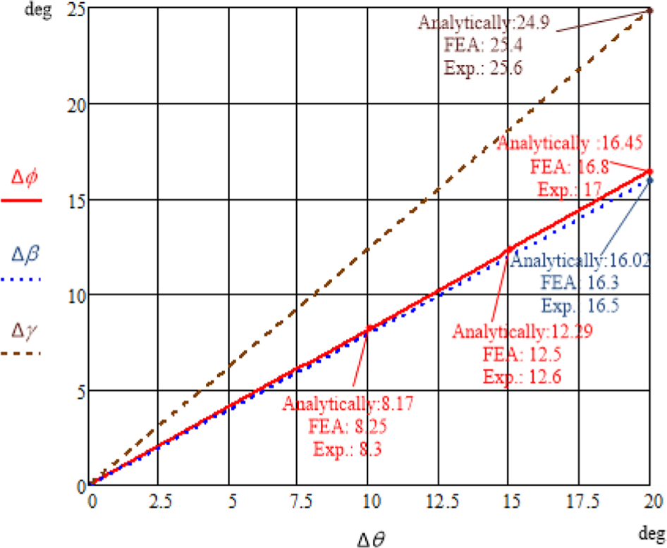
Deflections of the compliant segments.
The solid model of the compliant mechanism is exported to a finite element analysis (FEA) software (ANSYS®) for further analysis. The large deflection mode is activated and the nonlinear analysis option is selected. Solid Tetra 10 and Brick 20 elements with mid-nodes are used. Two quadratic (with midside nodes) elements along the minimum thickness are used. For the compliant segments of the mechanism, the element size is chosen as 0.5 mm. First, the motion of the solid model is simulated in ANSYS®, as presented in Figure 6; the T-shaped extension of the input rigid segment is rotated (10°, 15°, 20°) about the Z-axis, and directional deformations (m) at the Y-axis are determined. By measuring the positions of specific predefined points from FEA, we calculated the deflections of the compliant segments Δθ, Δϕ, Δβ, and Δγ (°) from the geometry of the mechanism. It is calculated that the deflections of the flexural hinges are approximately 1%–2% (the amount of error increased as the deflection increased) larger than the values that are determined analytically as shown in Figure 5.

Calculation of the deflections of the flexural hinges by finite element analysis.
The FEA technique is again utilized to obtain the resultant stresses at the compliant segments. The resultant stress at the compliant segments calculated by ANSYS® is the equivalent (von Mises) stress (Pa). The solid model of the mechanism is presented in Figure 7, where Δθmax = 20°, Δϕmax = 16.45°, Δβmax = 16.02°, and Δγmax = 24.9°. Maximum stresses at compliant hinges occurred while the deflections are at the maximum, and they are calculated analytically from equation (27) as σ14 = 21.8 MPa, σ12 = 17.5 MPa, σ23 = 27.2 MPa, and σ34 = 17.9 MPa. During the FEA simulations, stress values are measured from different points on compliant hinges (Figure 7(a)–(d)). It is verified that the average of the resultant stress on each compliant hinge is in close agreement with the corresponding theoretical value, as shown in Figure 7. For the selected material, the yield strength is equal to 35 MPa. The maximum stress value even at the most deflected compliant hinge (2-3) is smaller than the yield strength. Therefore, it is ensured to be in the safe elastic region.

Measurement of stress values at the end of the stroke by FEA and enlarged view of flexural hinges: (a) 1-4, (b) 1-2, (c) 2-3, and (d) 3-4.
Finally, the analyzed mechanism is manufactured from single piece polypropylene plate with a thickness of 8 mm, via computer numerical controlled milling as shown in Figure 8. Due to easiness of manufacturing, there are no fillets at the ends of the compliant segments. The deflections of the compliant segments of the prototype are measured with the custom-built test setup. A steel probe is fixed on the extension of the output, and a steel protractor is fixed to the ground. The probe rotates with the output’s rigid segment. The pitch angles of the extension, probe, and protractor are the same (Figure 8(c)). Also, center of rotations of the output compliant hinge, probe, and protractor are coincident at the undeflected position. By this way, correct output rotation can be measured for a given input rotation. The relative angle between the rigid segments 1-2 and 2-3 is measured with a digital angle gauge. First, the input’s rigid segment is fixed to a certain position, that is, 20° and relative angles of the rigid segments are measured. Then, the input’s rigid segment is again fixed at 20° to measure relative angles of the rigid segments again. The same procedure is repeated 10 times successively. Then, the average of these data is calculated and presented in Figure 5 as the deflection of each compliant hinge. The same procedure is repeated for input angles of 10° and 15° to measure angle of the output’s rigid segment (red line in Figure 5), since input–output motion relationship has major significance. It is observed that the experimental values of the deflections of compliant segments are approximately 2%–3% (the amount of error increased as the deflection increased) larger than the theoretical values, as shown in Figure 5. Note that, flexure hinge notch shape affects the motion range, rotational axis shift, and precision.28,29 The mechanism is operated numerous times for a 20° input angle, and there is no indication of failure (neither a color change nor a tear) at the hinges.

Prototype of a fully compliant spherical four-bar mechanism: (a) measurement of angular motion of the output link with the probe and protractor, (b) top view at the free position, and (c) front view at the free position.
Conclusion
In this article, a novel fully compliant spherical four-bar mechanism with small length flexural hinges is introduced. The mechanism’s generalized analysis and design methodology are proposed. An optimization routine is developed for optimizing the arc lengths, resulting in maximum output rotation for a defined input with an acceptable amount of flexural hinge deflections.
The optimization routine, the listed conditions, and the design tables can be very useful during the initial design stage of a fully compliant spherical four-bar mechanism. Due to the initial planar position, input–output motion can be doubled with the mirror symmetry. After the analysis of numerous arc lengths, it is observed that the increments of the deflections of flexural hinges are approximately linear. The analytical results are verified with FEA and experiments. It is ensured that fully complaint spherical four-bar mechanisms that allow relatively large rotations without plastic deformations can be designed.
Spherical four-bar linkages have numerous applications. It is possible that a fully compliant spherical four-bar mechanism may be a good alternative for some of the applications of spherical four-bar linkages. We believe that this study can also be a pioneer for other scientific researches on fully compliant spherical four-bar mechanism.
Footnotes
Handling Editor: James Baldwin
Declaration of conflicting interests
The author(s) declared no potential conflicts of interest with respect to the research, authorship, and/or publication of this article.
Funding
The author(s) received no financial support for the research, authorship, and/or publication of this article.