
Abstract
Stick-slip phenomenon in some mechanical structures, especially in machine tools, should be eliminated or inhibited, otherwise the vibration will occur and the position error will inevitably be obtained. In this study, different kinds of surface textures were carried out on the lower samples of the pin-on-disk contact. The starting process of the machine tools was simulated on an Rtec-Multi-Function Tribometer. The stick-slip phenomenon was observed in each kind of samples. However, the stick-slip phenomenon of smooth sample is larger than that of the textured samples. The bulge-textured surface shows excellent anti-stick-slip effect, and the critical stick-slip speed of bulge-textured surface is 95.9% lower than that of the smooth surface. Simultaneously, the anti-stick-slip effect of bulge-textured surface is superior to that of the dent-shaped texturing surface. What’s more, when the amount of lubricating oil is 15 mL, the standard deviation values of friction coefficient and critical speed of stick-slip phenomena (rotational speed when the standard deviation of friction coefficient is abrupt) are the lowest at different rotational speeds. It can be predicted that the bulge textures and adequate amount of lubricating oil (15 mL) can eliminate stick-slip phenomenon when processed in the surface of the machine tool because the bulge textures and adequate amount of lubricating oil can improve frictional state effectively and avoid the slip of the contact surface.
Keywords
Introduction
Under some circumstances, especially at low speed and heavy load, a sliding motion between two contact surfaces does not always generate constant friction force, but the motion changes between adhesion and sliding periodically. 1 This unstable motion of vibratory friction is called jerky motion or stick-slip phenomenon, which will be repeated in rapid succession until the slide reaches a certain velocity (critical speed).2–4 The stick-slip phenomenon exists mainly when the machine tool table operates at heavy load and low speed, and the motion is in mixed or boundary lubrication instead of hydrodynamic lubrication. Therefore, the lubricant film cannot carry all the loads and the static friction force is larger than the kinetic friction force when the two surfaces slide on each other.5–8 This unstable motion should be eliminated especially in CNC (computer numerical control) machines. Otherwise, the exact positioning will never be achieved. 9 In addition, the characteristics of lubricants (such as bonded coating, grease, and liquid) will affect the noise of stick-slip behavior caused by tribological contact between materials, and the stick-slip characteristics of lubricating oil will greatly reduce as the viscosity of lubricating oil increases. 1
Recently, a great deal of research has shown that changing the contact state between the surfaces appropriately can effectively improve the tribological properties of the surfaces. S Das et al. 10 studied the stick-slip friction influence on the performance of the gecko-mimetic adhesives and believed that stick-slip friction would reduce the properties of gecko-mimetic adhesives. M Trabelsi et al. 11 reported that the friction and wear properties of polytetrafluoroethylene (PTFE) matrix composites were improved significantly under oil lubrication.
Laser surface texturing (LST) technology, as a newly developed advanced surface texture technology, has attracted more and more attention from experts and scholars because of its advantages of high processing accuracy, fast processing speed, non-contact processing without damage to the surface, and environmental protection. Most importantly, it can greatly improve the lubrication and friction properties between materials. 12 Bulges and dimples (grooves) are two basic surface texture shapes. For an oil storage tank, dimples (grooves) can increase the hydrodynamic pressure effect in the low-speed zone and significantly reduce stick-slip in boundary lubrication, thereby improving the positioning accuracy of machine tool guideways. 13 It can also affect the tribological behavior of railway brake system and reduce or even suppress noise. 14 The deformable high harness surface texturing is applied in roll, which can extend the service life, form corresponding pits, and improve the stamping forming ability, surface image clarity, and surface coating properties.15,16 In addition, laser texture processing can increase the roughness of the non-data area of ordinary disk, reduce the static friction and head wear, extend the service life of the head, and increase the storage capacity of disk .
It can be reasonably assumed that under oil lubrication conditions, LST can effectively improve the contact state and tribological behavior of the sliding friction pair surface and have a positive effect on the suppression of stick-slip phenomenon. However, the application of laser surface texture technology to the surface of slideway friction pairs has not been systematically studied, and the effects of different texture surface morphologies on the surface stick-slip phenomenon of slideway friction pairs are rarely compared. In order to better suppress the stick-slip phenomenon of the machine guide rail, this article simulates the initial working condition of the machine guide rail on the friction test machine and explores the influence of different texture surface morphologies on the stick-slip phenomenon of the friction surface of the guide rail. Consequently, the comprehensive influence of different lubricating oil amount and different texture surface morphologies on stick-slip phenomenon are compared, which provides theoretical guidance for the application of surface micro-texture morphology on friction surface of guide rail.
Experimental details
Experimental equipment and methods
The crawling principle of machine tool guideway proposed by Soviet scientists in 1960s has been widely accepted. The driving parts start to move first, and the moving parts stop due to the friction between the moving parts and the guide rail. When the driving force (elastic deformation force of the driving system) used on the moving part exceeds the static friction force, the moving parts start. In this instant, static friction turns to dynamic friction, and the speed of moving parts is further accelerated due to the relatively small dynamic friction force. At the same time, the elastic deformation of the driving system decreases rapidly, even the direction of driving force changes. Finally, the moving parts are decelerated and the speed turns to zero.
A MFT-5000 Multi-Function Tribometer (Rtec instruments, USA) was used to observe the stick-slip phenomenon and the friction and wear properties. The pin-on-disk configuration was selected to simulate the surface-to-surface contact form of sliding guideway friction pair. The physical map of the contact form and the sizes of the upper and lower samples are shown as Figure 1. The upper sample keeps still, while the lower sample rotates.

Contact form and dimensions of upper and lower samples.
In order to simulate the low-speed and heavy-load working condition of machine tool when it starts, the load was set to 700 N and the rotational speed changed from 0.5 r/min and increased by 0.5 r/min for every 1 min of operation until the speed increased to a certain value. During the whole operation time, slick-slip phenomenon occurs first because of the low speed and the friction coefficient has a large vibration. However, the slick-slip phenomenon fades away with the increase in the rotational speed and the friction coefficient tends to be stable. There is a critical point in this process when slick-slip phenomenon disappears, which is called critical speed of the stick-slip phenomenon. However, the standard deviation values of the friction coefficients under different rotational speeds can reflect the vibration circumstances of the friction forces. Specifically, the standard deviation values of the friction coefficients are large at the low speed and decrease as the rotational speed increases. Similarly, a critical speed exists during the process when the standard deviation values of the friction coefficients decrease.
LST process
The substrate material for upper and lower samples was GCr15 bearing steel with a hardness of 60–65 HRC after quenching. Before testing, both upper and lower samples were polished using the metallographic abrasive papers with a grit size ranging from 180# to 1500# before using a polishing machine for the final polishing. After polishing, the average surface roughness was 0.05 μm. In order to change the contact form between the friction pairs, five kinds of lower samples were prepared as Table 1 (the upper samples were smooth). In Table 1, S1 is the smooth sample which represents the control group, while S2, S3, S4, and S5 are different kinds of textured samples which represent the observation groups. The S2 sample was produced by a fiber optic microsecond laser with the laser parameters of 70 W and 1000 μs, while S3, S4, and S5 samples were processed by an acousto-optic Q diode-pumped YAG laser (laser power 15 W, wavelength 1064 nm, the pulse width 70 ns, and frequency 50,000 Hz).
Features of five lower samples.
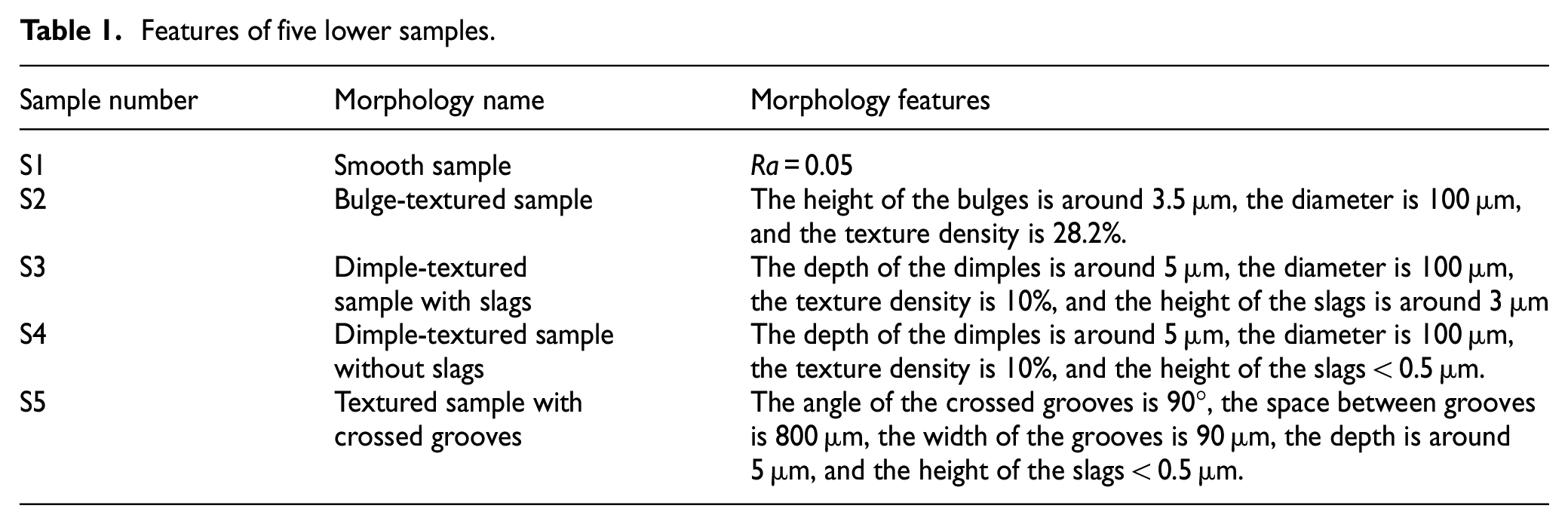
In particular, the laser thermal effect will produce slags around the textures. In order to obtain the dimples and grooves with smooth border, the S3 and S5 samples were polished and cleaned ultrasonically in acetone to wipe off the slags after laser texturing. However, to explore the influence of slag bulges on the stick-slip phenomenon, the slags of S4 samples were retained after laser processing and the height of slags around the micro-dimples (Figure 2) is about 3 μm. The morphologies of the samples were observed by a confocal microscope (nanofocus, Germany).

Different texture morphology features: (a) bulge-textured sample (S2), (b) dimple-textured sample with slags (S3), (c) dimple-textured sample without slags (S4), and (d) textured sample with crossed grooves (S5).
Results and discussion
Comparison of stick-slip phenomenon of different kinds of surface morphology
The stick-slip phenomenon usually occurs at the beginning of starting process because of the difference between the kinetic and static friction coefficients. Figure 3 shows the friction coefficient curves of the smooth sample at the load of 700 N and the rotational speed in the range of 0.5–25.5 r/min. The friction coefficient shows a large amplitude of vibration from the beginning of the relative motion until the rotational speed reaches 24.5 r/min. In other words, the critical speed of stick-slip process is 24.5 r/min under this circumstance. What’s more, it can be seen from Figure 3(b) that before rotational speed reaches the critical value, the friction coefficient changes periodically and constantly from a larger value to a smaller one, that is because the motion alternates periodically between adhesion (static) and sliding during stick-slip process. 1 In one changing cycle, the largest friction coefficient is the static friction and it will drop to a smaller value if sliding occurs. However, when rotational speed exceeds the critical value, the friction coefficient tends to be stable because the adhesion phenomenon gradually disappears with the increase in the rotational speed. Figure 3(b) also illustrates that the larger value of the friction coefficient has disappeared when rotational speed is greater than 24.5 r/min. Thus, it can be concluded that the static friction has been inexistent, and it is always dynamic friction at this period. In terms of the motion state, the sliding process occurs all the time and the stick-slip phenomenon fades away after the rotational speed reaches the critical value (24.5 r/min in this case), which conforms to the rule of stick-slip phenomenon. Figure 4 shows the variation of friction coefficient standard deviation values at different rotational speeds for the smooth sample. As is known, standard deviation values reflect the extent of variation of the friction coefficient at some rotational speed in 1 min. The standard deviation value shows a decreasing trend with the increase in the rotational speed. It can be seen that before reaching critical speed, the standard deviation is relatively large because the stick-slip phenomenon leads to a strong vibration of the friction force. However, when stick-slip phenomenon disappears, a smooth movement can be obtained and the amplitude of friction force decreases; hence, the standard deviation of friction coefficient also decreases to a relatively low value. The critical speed shown in Figure 4 is 24.5 r/min, which is in accordance with what Figure 3 reveals.

The coefficient friction changes with time for the smooth sample.

The standard deviation value of the friction coefficient changes with the rotational speed for the smooth sample.
Figure 5 illustrates the friction coefficient curves of the textured samples with different kinds of surface morphologies (S2–S5 samples). It can be clearly seen that all kinds of the textured samples have obvious anti-stick-slip phenomenon comparing with the smooth sample, and the critical speed values of the textured samples are 1, 7.5, 9.5, and 11.5 r/min,, respectively, when stick-slip phenomenon fades away. Figure 6 shows the variation of friction coefficient standard deviation values at different rotational speeds for the samples of S2–S5. It can be seen that the variation tendency of the vibration for friction coefficient and the critical speed for stick-slip also conforms to what is shown in Figure 5. So far, it can be confirmed that the technology of surface texturing can effectively inhibit the stick-slip phenomenon.

The coefficient friction changes with time for different textured samples.

The standard deviation value of the friction coefficient changes with the rotational speed for different textured samples.
Figure 7 reveals the critical speed when the stick-slip phenomenon disappears for different kinds of samples. It can be seen that the critical speed values of S2–S5 samples (textured samples) are obviously lower than those of S1 sample (smooth sample). The critical speed of S1 sample can be defined as


Critical speed for stick-slip phenomenon of different textured samples.
According to Figure 7, the inhibition efficiency values of S2–S5 samples are 95.9%, 69.4%, 61.2%, and 49%, respectively. Among them, the difference between S3 and S4 samples is that the slags caused by laser thermal effects were left around the dimples of S3 sample, while the S4 sample was polished after laser processing and the surface around the dimples is relatively smooth. Thus, it can be concluded that the textured surface with “bulge” morphology (S2 and S3 samples) has better anti-stick-slip effect comparing with the dent-shaped textures (S4 and S5 samples).
Figure 8 shows the schematic diagram for anti-stick-slip phenomenon of three kinds of surface morphologies. Figure 8(a) reflects the contact form of two smooth surfaces. The untextured upper surface contact with the bulge-shaped and dent-shaped texturing surfaces is shown in Figure 8(b) and (c), respectively. It can be seen that the actual contact area of the smooth surface is the largest among these three contact forms and has the maximum number of touchpoints under the same normal pressure. Thus, it will be more difficult to overcome the static friction force and start moving, which means the stick-slip phenomenon is more likely to happen. When it comes to textured surfaces, if bulge textures exist, the surface-to-surface contact is replaced by several point contacts as Figure 8(a) shows and the number of touchpoints significantly reduces. Therefore, the sliding motion is more likely to occur and the stick-slip phenomenon can be effectively restrained. However, the anti-stick-slip mechanism of dent-shaped texturing surface is different from that of the bulge-textured surfaces because the dimples or grooves morphologies have the capability to reserve lubricating oil, and the lubricating film thickness will increase. Therefore, the static friction force which needs to be overcome will reduce and the stick-slip phenomenon can be controlled. According to the conclusion above, the anti-stick-slip effect of bulge-textured surface is superior to that of the dent-shaped texturing surface.

The schematic diagram for anti-stick-slip phenomenon of three kinds of surface morphologies.
The stick-slip phenomenon of different kinds of surface morphologies changing with payload
Section “Comparison of stick-slip phenomenon of different kinds of surface morphology” shows that all of the four different kinds of textured surfaces have the effects of inhibiting stick-slip phenomenon and the inhibition function follows the order: bulge-texturing > dimple-texturing with slags > dimple-texturing without slags > crossed grooves texturing. In order to verify the correctness of this conclusion, the tribological tests of S1–S5 samples were carried out under the load of 100, 200, 300 400, 500, 600, and 700 N, respectively, when the rotational speed remained at 10 r/min and the duration time of each working condition was 1 min, and then, the vibration of friction coefficient was observed. Figure 9 shows the standard deviation values of the friction coefficient under different loads.
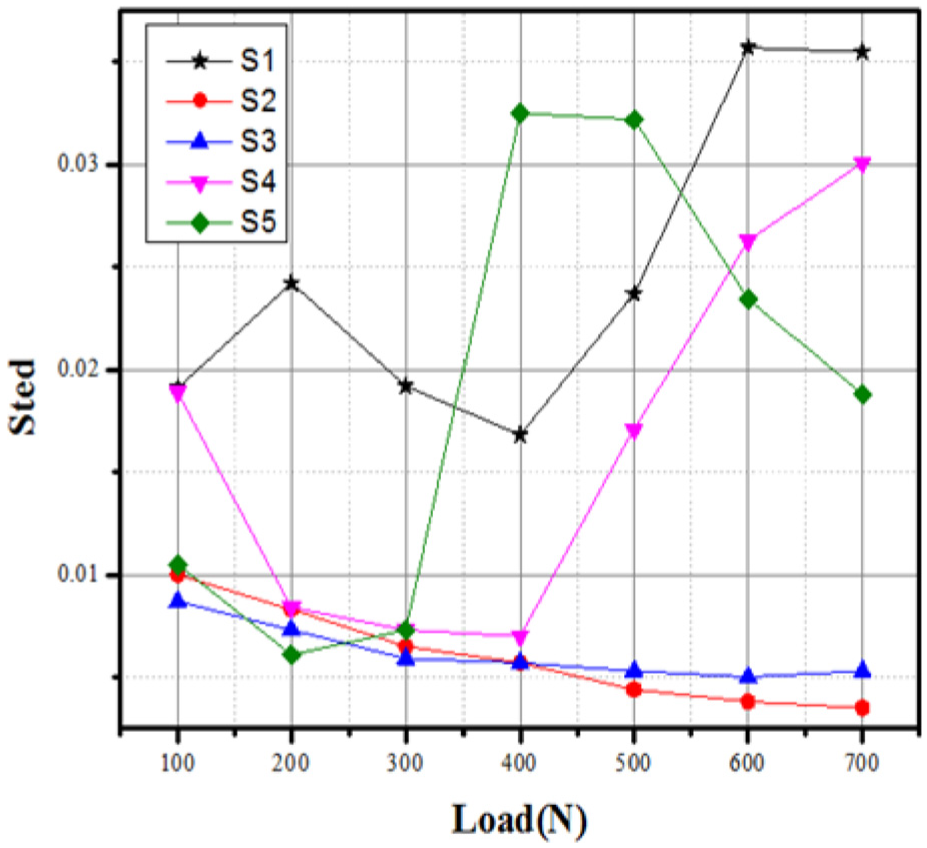
The standard deviation values of the friction coefficient change with the load for different textured samples.
It can be seen from Figure 9 that the standard deviation values of friction coefficient (hereafter referred to as STED) for different kinds of surface morphologies present large difference with the increase in the load. First, the STED value of S1 sample has been high under different loads and the friction coefficient fluctuates greatly all the time, which means the stick-slip phenomenon of smooth sample always exists under the load ranging from 100 to 700 N. However, the STED values of S2 and S3 samples are always in a low state and stick-slip phenomenon rarely occurs throughout the whole moving process. Besides, the STED values of S4 and S5 samples are relatively small under lower load and the motion is steady, but a sudden increase occurs when the load increases to certain value, which means stick-slip phenomenon starts to happen and this load value can be called critical load for stick-slip phenomenon. The critical load values for S4 and S5 samples are from 400 to 500 N and 300 to 400 N, respectively. In addition, according to the analysis above, the critical load for S1 sample is less than 100 N, and it is more than 700 N for S2 and S3 samples. The larger the critical load, the less likely it is to crawl. Therefore, the conclusion is consistent with section “Comparison of stick-slip phenomenon of different kinds of surface morphology.”
The effects of lubricating oil amount to the stick-slip phenomenon of different kinds of surface morphologies
In order to explore the effects of lubricating oil amount on the stick-slip phenomenon of different kinds of surface morphologies, frictional tests under the initial working condition of machine tool (the load is constant at 700 N and the rotational speed varies from small to large) of S1–S5 samples were carried out in 0.5, 5, and 15 mL volumes of lubricating oil, respectively. Figure 10 shows the STED values of smooth sample in different volumes of lubricating oil. It can be seen that the STED values of smooth sample demonstrate a big difference with different amounts of lubricating oil. First, the STED value in the lubricating oil amount of 0.5 mL is always larger than that in the lubricating oil amount of 5 and 15 mL at different rotational speeds. Besides, the STED values between 5 and 15 mL of lubricating oil are almost unanimous. When the amount of lubricating oil is insufficient (0.5 mL), the surface of friction pair is in a state of poor oil lubrication and the static friction force is larger. Thus, the crawling vibration is more intense. However, if the lubricating oil is sufficient, the static force will decrease and the coefficients of kinetic friction and static friction may tend to be the same. Therefore, the intensity of stick-slip phenomenon will reduce. In general, when the STED value is larger, the crawling vibration is more intense. Therefore, when the oil quantity is small and almost oil-poor, the stick-slip phenomenon is the most intense and the critical speed of the stick-slip phenomenon is larger. In the actual working state, the phenomenon of larger crawling vibration due to lean oil also occurs. Thus, the conclusion is consistent with the actual working state.

The standard deviation values of the friction coefficient change with the speed with different amount of lubricant oil under initial working condition of the machine tool for the smooth sample.
Figure 11 shows the STED values of different kinds of textured samples under different rotational speeds. It can be seen that the bulge-textured sample of Figure 11(a) and the dimple-textured sample with slags of Figure 11(b) show almost the same effect of inhibiting stick-slip phenomenon in different lubricating oil quantities, and there is no significant difference in the critical speeds of the stick-slip phenomenon. The dimple-textured sample without slags of Figure 11(c) and crossed groove–textured sample with slags of Figure 11(d) show different effects of inhibiting stick-slip phenomenon in different lubricating oil quantities.

The standard deviation values of the friction coefficient change with the speed with different amount of lubricant oil under initial working condition of the machine tool for different textured samples.
When the amount of lubricating oil is insufficient (0.5 mL), the STED values and the critical speeds of the stick-slip phenomenon (rotational speed when the standard deviation of friction coefficient is abrupt) at different rotational speeds are larger. However, with the increasing amount of lubricating oil, the standard deviation of friction coefficient and the critical speeds of the stick-slip phenomenon at different rotational speeds decrease significantly. Besides, the STED value and the critical speed of 15 mL oil are slightly lower than those of 5 mL oil.
Comparing different kinds of three-dimensional (3D) surface morphology of each sample (Figure 2) to analyze the causes of this phenomenon, it can be concluded that the bulge-textured sample of Figure 11(a) and the dimple-textured sample with slags of Figure 11(b) both have the bulge-shape. When the two planes are in contact, the bulge-shape of the textured sample comes into contact with the upper sample (smooth surface), and the suppression of the stick-slip phenomenon is mainly due to that the bulge-shape of the textured sample suppresses the stick-slip phenomenon between the two planes. Besides, the height of bulge-shape of textured sample may be slightly higher than the thickness of the lubricating film, and the amount of lubricating oil has no absolute influence on the stick-slip phenomenon. Therefore, the stick-slip inhibition effects of S2 and S5 samples under different lubricating oil amounts are almost the same.
However, the dimple-textured sample without slags of Figure 11(c) and crossed groove–textured sample with slags of Figure 11(d) both have the dent-shaped texturing surface. The dimples or grooves morphologies have the capability to reserve lubricating oil. When the upper samples and lower samples are in contact and move relative to each other, there is a certain thickness of the lubricating oil film between the upper and lower samples. Therefore, the thickness of the lubricating oil film may have some influence on the stick-slip phenomenon. The more amount of oil is stored in the dimples or grooves, the deeper thickness of the lubricating oil film is, and the more obvious the crawling suppression effects are. It can be seen that the suppression effects of the stick-slip phenomenon of S2 and S5 samples are mainly due to the lubricating oil film when the upper and lower samples move relatively to each other. Therefore, a greater influence can be made on the stick-slip phenomenon by the amount of the lubricating oil.
Conclusion
This article simulates the initial working condition of the machine guide rail on the friction test machine and the main conclusions are as follows. First, the inhibition function of bulge-textured sample is the best and the inhibition function of different surface morphologies follows the order: texture surfaces with “bulge” morphology (bulge-textured sample and dimple-textured sample with slags) > dent-shaped textures (dimple-textured sample without slags and textured sample with crossed grooves) > smooth. Second, when the amount of lubricating oil is insufficient (0.5 mL), the crawling vibration is intense. However, if the lubricating oil is sufficient, the amount of lubricating oil has little effect on the bulge morphology, but has certain effect on the dent-shaped textures.
With the advent of the era of intelligence, high-end CNC machine tools, as the working machine of intelligent manufacturing in equipment manufacturing industry, are important symbols to measure the development level and product quality of a country’s equipment manufacturing industry. For this reason, it is of great practical significance to apply LST technology to the guide rail of machine tool to make the surface of the guide rail have “bulge” morphology, and the amount of lubricant oil is more than 5 mL, which can reduce the crawling vibration and stick-slip phenomenon of the guide rail, improve the positioning accuracy of machine tool, and prolong the service life of machine tool.
Footnotes
Handling Editor: Jixiang Yang
Declaration of conflicting interests
The author(s) declared no potential conflicts of interest with respect to the research, authorship, and/or publication of this article.
Funding
The author(s) disclosed receipt of the following financial support for the research, authorship, and/or publication of this article: This research was supported by the National Natural Science Foundation of China (Grant No. 51975252), the National Key Research and Development Plan: High Efficient Facility Agricultural Spraying Technology and Intelligent Equipment (grant no. 2016YFD0200708), and Science and Technology Project of Jiangsu Province (grant nos. BE2017122 and BE2015095).