
Abstract
The contact problem of system of particles rolling over a viscoelastic layer bonded to the rigid half-space was considered. Particles have a spherical shape and their radiuses are distributed along Gauss. Earlier, the friction coefficient was obtained for the particles between surfaces in the relative movement of the surfaces using the three-body interaction method. In this study, the contact area was calculated for a system of particles rolling over the viscoelastic layer bonded to the half-space. Using the three-body interaction approach, the friction coefficient was calculated, taking into account the rolling of particles. The results demonstrate that the coefficient of friction, calculated using the three-body model, decreases when the rolling of particles is taken into account.
Introduction
Real sliding and rolling contacts are characterized by the presence of particles (third body), which should be taken into account in calculations of actual contact area. There are three types of contact behavior depending on the wear debris. It can be surface-to-surface two-body contact, three-body contact, and particle-to-surface two-body contact. The surface-to-surface two-body contact takes place when the diameter of the particle is smaller than the gap between surface asperities. The particle-to-surface two-body contact realizes when the particle diameter and the number of particles per unit area are larger, so there is the gap between surfaces. Three-body contact is an intermediate case, which can be realized by increasing load and decreasing the gap in surface-to-surface case.
The contact problem between two rough surfaces was investigated in many studies beginning with the fundamental work by Greenwood and Williamson. They proposed the Greenwood–Williamson (GW) model of multiple contact and established the criterion to determine elastic and plastic deformation of asperities. 1 Based on the GW model, other approaches to study contact between rough surfaces were developed. The fractal model of contact between isotropic rough surfaces based on the scale-independent fractal roughness parameters was developed by Majumdar and Bhushan 2 and Ciavarella and Demelio. 3 The approach to describe contact surfaces by the combination of trigonometric functions was described by Ciavarella et al. 4 In previous studies,5–8 rough surfaces simulations based on numerical calculation methods involving finite-element (FE) approaches were presented. Models based on the simulation of the multiscale roughness in the form of a periodic function and nonlinear soft layer were developed by Goryacheva.9,10 An analytical solution for a contact problem, where the wavy surface was represented by two cosine harmonics without accounting for the frictional forces, was obtained by Tsukanov. 11
The behavior of wear debris trapped in the contact region is still not well understood. There were several researches where the effect of third-body particles on contact characteristics was investigated. The material continuum and granular medium models of wear debris were discussed by Zmitrowicz. 12 Within the framework of suggested models, the dependence of the friction coefficient and wear rate on the presence of the wear debris were studied. Ghaednia and Jackson 13 presented the approach to model nanoparticles in contact between rough surfaces. The results suggested that the presence of particles reduces the real contact area and friction force. The third-body contact model for two rough surfaces and particles of different sizes defined by a distribution function was developed by Ghaednia et al. 14 A statistical approach was used to model the contact of surface asperities and particles. The combination of the caulking effect, covering effect, and three-body elastic contact model was suggested to analyze the mechanical properties of large particles in the powder lubrication process by Wang et al. 15 The relation between load and the contact area and the separation between the two surfaces in the presence of a third body was determined. Three-body microcontact model for rough surfaces was proposed by Horng 16 in application to the polishing of wafer. Simplification of this model allows obtaining the transitional surface-to-surface and particle-to-surface two-body microcontact simulations. The model of three-body microcontact with elastic deformation was described by Horng-Wen et al., 17 where the contact temperature was calculated for different size and density of wear particles and friction coefficient.
In the upper mentioned studies, the third-body contact models were developed neglecting the motion of wear debris. Taking into account the imperfect elasticity of surface, the rolling of wear debris affects the contact characteristics such as friction coefficient and contact area.
The rolling contact of two cylinders with the viscoelastic layers such as rubber was considered by Kalker 18 and Braat and Kalker. 19 The research about rolling friction when the layer is modeled with Maxwell body is presented by Goryacheva and Sadeghi 20 and Goryacheva. 21 The resistance force for rolling problem when one of the bodies surfaces has the viscoelastic coating was studied by Morozov and Makhovskaya, 22 where the Kelvin model was used to describe the mechanical properties of the layer. The internal stresses of elastic bodies in rolling contact with the layer were analyzed by Goryacheva et al. 23 The three-dimensional (3D) contact problem for a rigid sphere rolling over a viscoelastic layer bonded to the rigid half-space with the evaluation of traction force and the configuration of stick and slip subregions was considered by Miftakhova. 24
In this article, the third-body contact model, along with the rolling of particles, is considered. We assume that wear debris or foreign particles presented in the interface of contact bodies are rolling and there is always some gap between the surfaces. Lower surface is covered with the viscoelastic layer, modeled with the Kelvin body. The 3D contact problem of system of spherical particles rolling over a viscoelastic layer coupled to a base is considered. In modeling, the contact problem is divided into two parts: the calculation of actual contact area for one rolling particle and the contact problem of the system of particles between surfaces, neglecting the interaction between particles.
Contact problem formulation
Three-body microcontact theory
The three-body contact system, which consists of rough surfaces and rolling particles, located in the gap between surfaces, is considered. According to Chang et al. 25 the contact of two rough asperities can be assumed as the contact of a plane with an equivalent rough surface.
Figure 1 shows the geometry of the contacting bodies, where viscoelastic layer (3) is bonded to the lower surface (2). It is assumed, that particles are rigid and the contact interface is under dry friction conditions.
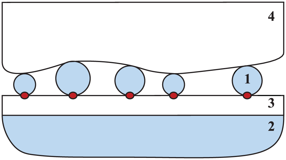
Geometry of particle-to-base three-body contact, where 1 is the particle, 2 is the surface, 3 is the interfacial layer.
Particles, located between two surfaces, have spherical shape and their diameters are distributed along Gauss

where xa is the mean diameter of the particle, and σa is the standard deviation of the particle diameter.
The contact problem of rolling particles over a viscoelastic layer is considered within the framework of the three-body interaction model. 16 Originally, in this model, the particles themselves do not rotate; therefore, rolling contact model was added to consideration. Sliding of particles was not taken into account because particles are rigid and the total pressure and the penetration of particles into the surface layer are small. In problem formulation, it was assumed that the particles diameters are much smaller than the curvature radius of surface roughness. It follows, that the distribution and height of surface roughness did not affect the calculations, and the surfaces were considered as flat for each isolated contact.
Rolling contact model
To calculate the actual contact area for rolling particle, we consider the problem of sphere rolling over a viscoelastic layer coupled to a half-space. The sphere of radius R rolls along the base with a constant angular ω and linear V velocities. The motion of the sphere can be considered as steady with respect to a moving coordinate system associated with the sphere. In Figure 2, a scheme of the contact is presented.

Scheme of the rigid particle (1) rolling over the viscoelastic layer (3) bonded to the surface (2).
Let the system of coordinates Ox′y′z′ be connected with the layered elastic half-space and the system of coordinates Oxyz with the rolling sphere so that

The origins of fixed and moving coordinates systems are located on the layer surface under the center of the sphere at some initial instant of time.
The characteristic dimension of contact region is in order of magnitude smaller than the radius of the sphere, we use parabolical approximation to describe the shape of the sphere

where R is the radius of the sphere.
The Kelvin model is used to describe the layer compliance in normal direction (z = 0) 26

where v (x′, y′, t) is the displacement of the viscoelastic layer in normal direction, p (x′, y′, t) is the contact pressure, Tε, Tσ are the retardation and relaxation times, respectively, EL is the longitudinal modulus of elasticity of the layer in normal direction.
In the moving coordinate system (Oxyz), relation (4) is transposed to the following

Outside the contact region, the contact pressure is equal to zero.
Method of the contact area calculation based on three-body microcontact model
The method of the contact area calculation within the three-body microcontact model is presented by Horng. 16 Since the method is used here, its brief description is given as follows.
In the three-body microcontact model, the following assumptions are made:
All surface asperities are far apart, and there is no interaction between them;
There is no bulk deformation, only the surface asperities deform during contact;
Spherical particles of a radius R are much harder than both surfaces, and the surfaces deform plastically during contact with particles;
Slopes of surface asperities are negligibly small.
The contact interface is represented with the three-body contact system in the relative movement of the components. Therefore, the total contact area Atotal consists of As1s2–s1a and As1a, where As1s2–s1a is the real contact area for surface-to-surface contact, and As1a is the real contact area for particle-to-surface contact. Based on the model described by Horng-Wen et al., 17 it follows that the total contact area Atotal can be expressed as
where An is the nominal contact area, ηa is the number of particles per unit area, As1s2 is the real total contact area of two-body microcontact models as per the Zhao–Maietta–Chang (ZMC) two-body microcontact model, 27 xmax is the maximum particle diameter, xmin is the minimum particle diameter, Es1a is the equivalent elastic modulus of upper surface and the particle; Es2a is the equivalent elastic modulus of layer and the particle.
The actual number of contact particles
where d is the separation based on asperity heights.
Equation (6) is used to calculate the total contact area for system of particles. To receive the contact area for single particle, result of calculation is divided by the number of particles, which are located in actual contact.
Method of the contact area calculationfor rolling particle
We use the strip method described by Haines and Ollerton 28 to calculate the contact region in rolling contact problem.
The relation between the total load P applied to the sphere and the contact pressure p(x, y) follows from the equilibrium condition

As the contact pressure distribution has a symmetry related to the axis, the calculations are made only for the half-width of the contact region. We can define the total load on the sphere with the following relation, where N indicates the number of strips at the half of contact region
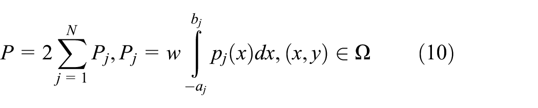
where Pj is the total load in the jth strip, w is the width of the strip, aj and bj are the boundaries of the contact region in the central strip, and Ω is the contact region.
The contact pressure in the boundaries of the contact region and outside it is equal to 0

The algorithm of contact pressure and contact region evaluation for single spherical particle rolling over the viscoelastic layer was described in more details by Goryacheva et al. 23
Friction coefficient analysis
According to Horng-Wen et al., 17 we can express the friction coefficient as sum of the following components: particle adhesion friction (μpa), adhesion friction (μa), and ratchet friction (μr) at the contact region. The calculation of the friction coefficient is described in more details by Horng-Wen et al. 17 We consider that the penetration of particles is small enough to assume that there is no plastic penetration, and all particles are rolling on the surface of the layer.
Neglecting the deformation component of friction and ratchet friction, the formula for friction coefficient is transposed to the following

where τa is the shear stress function, and P is the total load applied to the particle. In accordance with Adams et al., 29 τa = G/1000, where G is the shear modulus of the layer material
where E is the modulus of elasticity of the layer material in tangential direction, and ν is Poisson coefficient.
Taking rolling of the wear debris particles into account, we can calculate the actual area of contact region. The friction coefficient for three-body microcontact model with rolling particles can be calculated by substitution the actual value of the contact area for rolling particles in the formula for the friction coefficient equation (12).
Results and discussion
In calculations of rolling contact area for single particle, we use the following values of parameters, described in equation (4)

In three-body microcontact model, we fixed the values of parameters, introduced in equations (6)–(8) and (13)

We consider the longitudinal modulus of elasticity of the layer material in normal and tangential directions as equal.
The contact region configuration for rolling and motionless particle is illustrated in Figure 3.
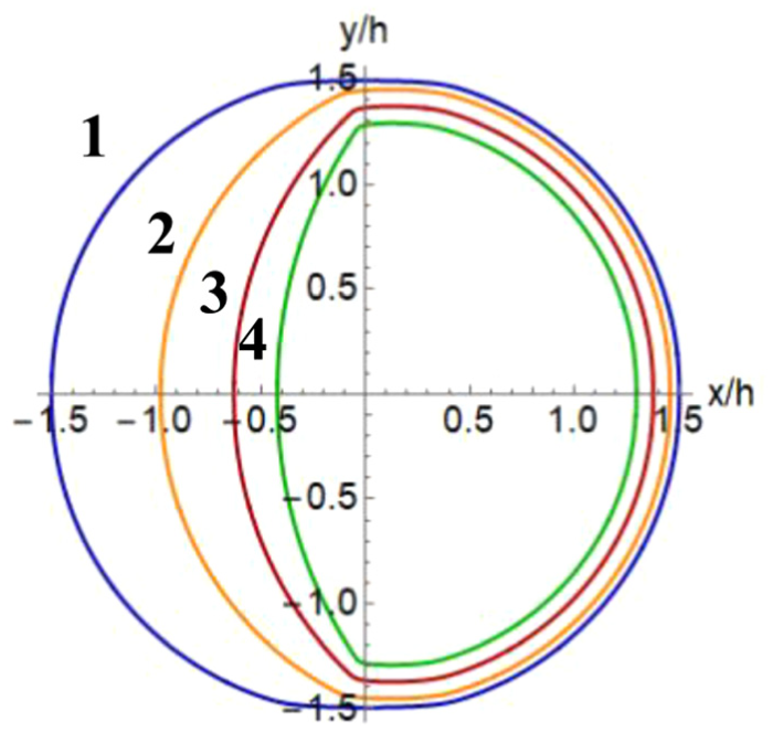
The contact region for particles without rolling (1) and rolling (2, 3, 4) particles, where the radius of particle R is 25 nm and 1—V = 0, 2—V = 2 nm/s, 3—V = 3 nm/s, 4—V = 4 nm/s, where P = 1 nN.
Figure 3 shows that the increase of rolling velocity of particle leads to the decrease of contact area and its shift in the rolling direction.
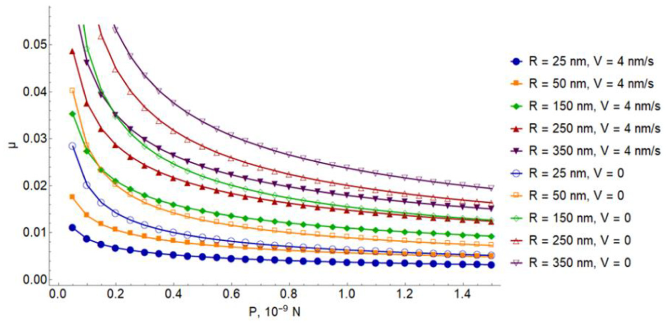
The friction coefficient was calculated within the framework of the three-body contact model, where the rolling of particles was taking into account. Figure 4 illustrates the dependence of the contact area on the load P for particles of various radius with and without rolling.

The dependence of the contact area on the load (P) for particles without rolling (hollow markers) and rolling particles (solid markers), where the radius of particle (R) is 25, 50, 150, 250, and 350 nm.
The results demonstrate that the contact area for rolling particle is lower when the contact area for particles without rolling. The effect of rolling on the contact area increases with the growth of radius of particle.
Figure 5 shows the dependence of the contact area on the load (P) for various rolling velocity of particles.

The dependence of the contact area on the load (P) for particles without rolling (hollow markers) and rolling particles (solid markers), where the radius of particle (R) is 25 nm and rolling velocity (V) is 4, 6, 8, and 10 nm/s.
Figure 5 demonstrates that the greater value of rolling velocity of particles corresponds to the less contact area.
Figure 6 illustrates the dependence of the friction coefficient on the load for particles without rolling and rolling particles of various radius.
The dependence of the friction coefficient on the load (P) for particles without rolling (hollow markers, V = 0) and rolling particles (solid markers, V = 4 nm/s), where the radius of particle (R) is 25, 50, 150, 250, and 350 nm.
The growth of the load applied to the particle corresponds to the decrease of the friction coefficient (Figure 6). The influence of rolling on the friction coefficient value is greater for less loads and larger particles.
Figure 7 illustrates the dependence of the friction coefficient on the load (P) for various rolling velocity of particles.

The dependence of the friction coefficient on the load (P) for particles without rolling (hollow markers) and rolling particles (solid markers), where the radius of particle (R) is 25 nm and rolling velocity (V) is 4, 6, 8, and 10 nm/s.
According to the results, presented in Figures 5 and 7, the growth of rolling velocity leads to the decrease of friction coefficient and contact area.
Figure 8 demonstrates the dependence of the contact area on radius of particle, where the load, applied to the particle, varies from 1 to 1.4 nN.
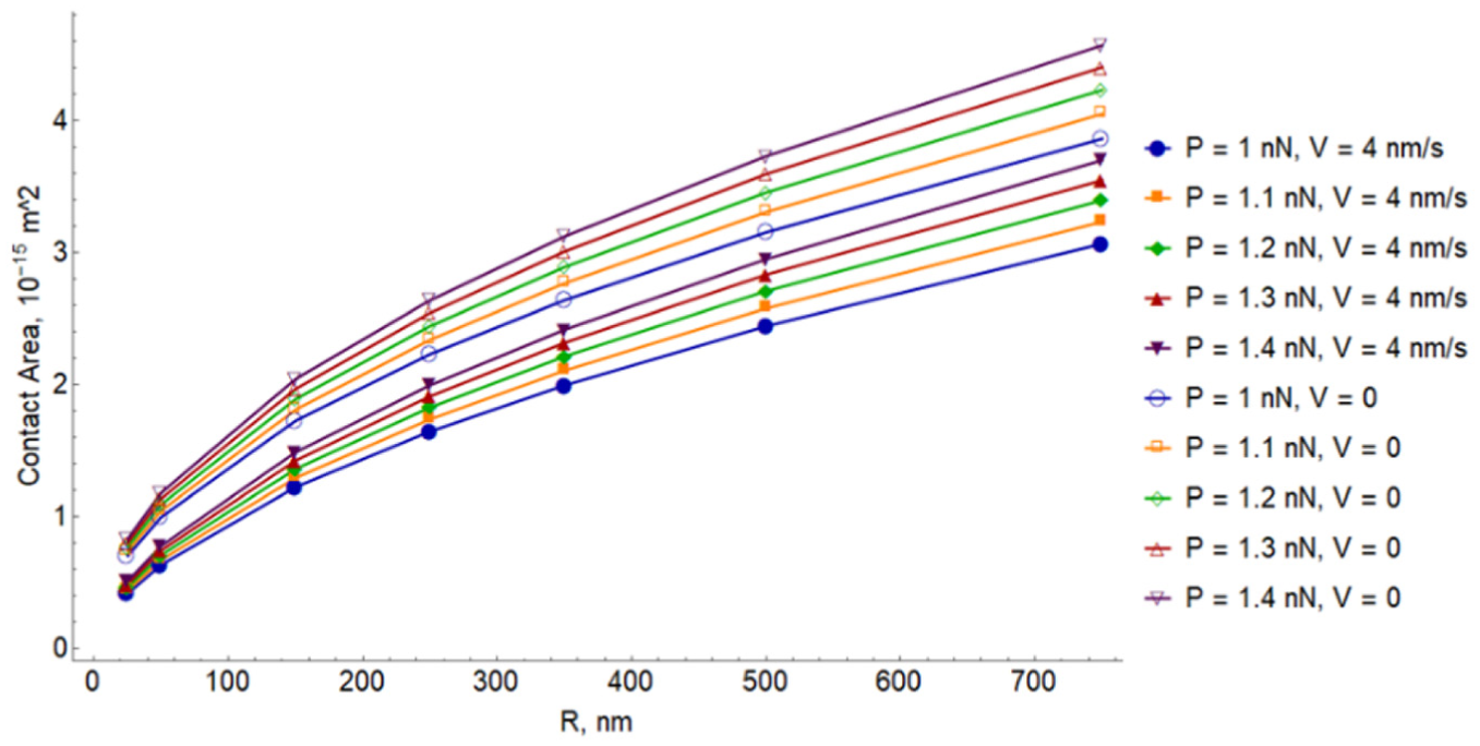
The dependence of the contact area on the radius of particles without rolling (hollow markers) and rolling particles (solid markers), where the load (P) is 1, 1.1, 1.2, 1.3, and 1.4 nN.
The results indicate that the growth of the radius of particle leads to the increase of the contact area.
The dependence of the friction coefficient on the radius of particle is presented in Figure 9.

The dependence of the friction coefficient on the radius of particles without rolling (hollow markers) and rolling particles (solid markers), where the load (P) is 1, 1.1, 1.2, 1.3, and 1.4 nN.
The results show that the difference between the friction coefficient values for particles of various radiuses is greater in case of rolling particles in comparison with particles without rolling. In Figure 9, it is more noticeable for larger particles.
Conclusion
In this work, the rolling contact model and the three-body microcontact model were combined to analyze the contact and frictional characteristics at various particle sizes and applied loads. The contact problem of rolling particles with radiuses distributed along Gauss in the interface between two surfaces was considered. The contact problem solution for rolling particles was investigated and compared to the results obtained for three-body system with the relative movement of components. The friction coefficient was calculated within the three-body microcontact method considering contact area for rolling particles.
Due to the imperfect elasticity of the layer, the contact area changes when we take into account rolling of particles. It was investigated that the actual contact area for rolling particle is lower than the contact area calculated without rolling. This result is in good correlation with the previous studies observed by Zmitrowicz 12 for the case of elastic rolling contact of particles. The results demonstrate that the effect of rolling on the contact area increases with the growth of the load applied to the particle.
Footnotes
Appendix 1
Handling Editor: Yunn-Lin Hwang
Declaration of conflicting interests
The author(s) declared no potential conflicts of interest with respect to the research, authorship, and/or publication of this article.
Funding
The author(s) disclosed receipt of the following financial support for the research, authorship, and/or publication of this article: This work was financially supported by Russian Foundation for Basic Research (grant no. 175852030).