
Abstract
As a method for reducing the friction of high-precision system, air bearings have been widely used for various industrial applications. However, their small damping leads to poor in-position stability and therefore systems are susceptible to residual vibration and disturbance. In this study, a linear motion stage which is guided by air bearing for a noncontact eddy current damping module is proposed. The eddy current damping module consists of a Halbach array of permanent magnets and a fixed conductor plate. An eddy current is generated in the conductor in the direction opposing the change in the magnetic field when the magnets move, after which the resistivity in the conductor dissipates the kinetic energy of the moving part; therefore, the module has a damping effect without contact and system is shown good in-position stability. In order to specify the damping effect, the motion of the moving part was experimentally analyzed. The step response confirmed that the eddy current damping module can improve the performance of the positioning system: the settling time decreased by 36.8% and the resolution improved by 59.4%. These improvements verify that eddy current damping is a suitable method for application in precision industries.
Introduction
Because of the miniaturization and large-scale integration of electronic devices, industry demands high accuracy for production processes. Accordingly, improvements in the precision of equipment used to manufacture electronic devices have been required. High precision in the positioning system is essential to improve such manufacturing equipment. Air bearings are one of the most widely used guides for high-precision positioning systems because they have many good properties. Air bearings allow moving parts to float on a thin air film, without contacting the system’s guide surface. The use of air bearings can overcome problems related to the roughness of the guide surface, and less friction is produced than other guide systems.1,2 However, a system with an air bearing guide has a very low damping force; therefore, it is difficult to control the precision position because of its vulnerability to undesirable vibration resulting from electrical noise and disturbances. Except for studies using physical eddy current damping (ECD), most previous research work has attempted to solve the problem of small damping using methods such as a Kalman filter and sliding mode control.3,4 These methods are able to correct electrical noise and relative high-frequency disturbances effectively. However, to implement a Kalman filter or a sliding mode controller, it is necessary to perform a specialized and complicated process that includes system identification, development of a control algorithm, and optimization. Because of the lead time of development is short in many situations, there is a limitation to designing a real and accurate controller that depends on each situation.5–7
Therefore, to relieve the low damping problem associated with air bearing systems, an ECD effect can be applied to the air bearing system. An eddy current, which interferes with the magnetic field change in a conductor, is created in the conductor. The current is dissipated by the conductor’s resistance. If the change in the magnetic field originates from moving permanent magnets, an eddy current is generated to resist this motion. At this time, this opposing force can be considered a kind of damping force because it is proportional to the velocity of motion. Because this damping force acts like a viscous damper, the problem of insufficient damping in air bearing systems can be solved by applying this principle. 8
E Simeu and D Georges 9 induced an eddy current brake model in a rotating disk. MT Thompson 10 studied how to change the force of eddy current brakes depending on velocity and applied it to rail transport. KK Tan et al. 11 carried out a study on the adaptive estimation of the damping parameter in their experimentally configured eddy current brake. B Ebrahimi et al. 12 applied ECD to automotive suspension systems.
There have been very few studies using ECD effects on air bearing–guided linear motion (LM) systems. KK Tan and colleagues11,13 adopted ECD in a 1-degree-of-freedom (DOF) system composed of air bearings, where the damping effect was approximated through an adaptive estimator. This method is effective for controlling a system that has already been configured; however, there is a limit to the design and characterization of ECD.
In this study, the design of a system to apply ECD to relieve the low damping problem associated with air bearing systems is proposed and analyzed. To improve the stability and response of ultra-precision LM systems using air bearings, it is necessary to design new ECD modules according to the principles and physical damping characteristics of the module. Therefore, a simple and structurally stable ECD module is fabricated in this study to improve the performance of an ultra-precision system guided by an air bearing. The characteristics of ECD are derived through the eddy current principle, and the physical damping characteristics are observed experimentally.
When mounting the ECD module in an ultra-precision system, it is desirable that the module can provide a large damping effect, despite the relatively small size and weight of the module. According to a study by SQ Lee et al., 14 a Halbach array was used instead of a conventional permanent magnet array because a Halbach array can generate 40% more magnetic flux than a conventional array. In other words, using a Halbach array means that there is a chance to reduce the size and weight of the module by approximately 40%. The increased magnetic field offers more eddy current, which results in a suitable damping effect. Therefore, ECD with a Halbach array can compensate for the insufficient position stability of the air bearing.
This study analyzes the characteristics of ECD. Air bearings have viscous damping caused by aerodynamic behavior. These and the effect of ECD together show nonlinear damping characteristics. This characterization will help not only design the ECD module, but also improve the stability and response of ultra-precision systems that utilize air bearings as guides.
Air bearing–guided LM system
Configuration of LM system
The target LM system is a one-axis positioning stage, as shown in Figure 1, which consists of a linear motor and air bearings. It is operated without any contact so has little friction. The ECD module on one side of the moving part makes it suitable for various positioning mechanisms. A Halbach array of permanent magnets, which has a strong magnetic field on the designated side, was used to maximize the effects of ECD. A laser interferometer, which is separate from the base of the driving unit, measures the displacement of the moving part. To compare the cases with and without the application of ECD, a conductor plate and backing iron are fixed over the LM-guided system, perpendicular to the movement of the air bearing, allowing an air gap between the magnets and conductor. The specifications of the components in the designed system are presented in Table 1.

Experimental setup of linear motion system with ECD module.
Specifications of LM system.

LM: linear motion; ADC: analog-to-digital converter; DAC: digital-to-analog converter.
ECD theory
An eddy current refers to the current that flows in a direction opposing the change in the magnetic field in a conductor moving in a magnetic field. In Figure 2, the eddy current is swirling in the conductor when the permanent magnet moves. When this eddy current and the permanent magnet interact with the current, a magnetic force is generated that provides a drag force relative to the movement of the permanent magnet. This force serves to dissipate kinetic energy, which is called the ECD phenomenon.

Principle of eddy current.
Proposed ECD module
The ECD module consists of a magnet array unit that generates a magnetic field and a conductor plate that experiences the eddy current effect according to changes in the magnetic field. The conductor has a backing iron with high permeability. The module has magnets attached to the side of the moving part, and its magnetic field does not have an effect on the magnetic field in the center of the moving part. The conductor is installed parallel to the moving direction and is as long and as wide as the moving area to generate an ECD effect over the entire region of the moving area. Because the ECD effect is generated between the magnets and conductor, it is effective to adopt a Halbach array magnet that has a strong magnetic field only in the direction of the conductor. The configuration of the designed Halbach array ECD is shown in Figure 3.

Design of ECD module.
Damping force from eddy current
When the moving part in the one-axis positioning system moves, a damping force caused by the eddy current induced by the damper module is given by

In equation (1), the damping force of the eddy current is affected by the shape factor


Halbach magnet array model using the image method. 15
In equation (2), the first term is the magnetic flux density of real magnets, and the second term is that of image magnets. The parameters in equation (2) are shown in Figure 4. The image magnets are intended to mimic the boundary conditions resulting from the backing iron above the red dotted line in Figure 4. At this time,

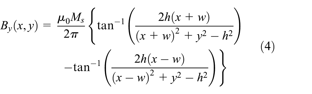
where


A single magnet for modeling.
The magnetic flux density of the proposed ECD module, with respect to the positions of the x- andy-axes, is theoretically determined. The theoretical model was verified using a finite element method (FEM) program (Maxwell Ansys Electronics 2017). The height, thickness, and width of the Halbach magnet array used for fabrication and analysis are 100, 15, and 70 mm, respectively. This design is intended to confirm the usefulness and characteristics of the ECD module. Therefore, the design criteria according to the requirements of the specific system will be determined when applying it specifically to the ultra-precise system in the future. However, the initial design was performed so that the Halbach magnet array mounted on the moving part generates a dense magnetic field in the conductor, thereby generating a large damping force. This initial design reflects the requirement that the size and weight of additional fixtures be small for quick response and stability with respect to the ultra-precision system. Generally, the size of the moving part of semiconductor or display manufacturing equipment is at least four times larger than the area of the eddy current generated by the ECD module in this study; hence, the initial design is realistic. As shown in Figure 6,

Comparison of magnetic flux density in x- and y-directions; the red line indicates theoretical method and the blue lines indicates analytical method.
Characterization of damping force
Control system setup
The configured system, which is a one-axis positioning system consisting of air bearings and a linear motor without ECD, can be described by equation (6). The TA330 Amp receives a voltage signal produced in the controller, and the corresponding amplified current is inputted to the linear motor. The movement according to the input current is given by equations (7) and (8)


The plant dynamics where the ECD effect is modified is shown as

where
The system that controls the movement of the configured system is shown in the block diagram in Figure 7, where

Block diagram of control system.

Experimental setup of LM system.
Experimental model of ECD
A motion test with constant speed was conducted to calculate the damping coefficient of the ECD module. Keeping the moving distance at 100 mm, the test was conducted by changing the moving speed in the range of 5–30 mm/s, with the gap between the magnets and the conductor varying from 23 to 30 mm. If the gap becomes smaller than 23 mm, misalignment of the air bearings occurs because of the attraction between the magnet and the conductor’s backing iron. The damping force and damping coefficient generated by the ECD were obtained as the air gap distance in the ECD module was varied for each constant speed.
If the ECD module is not applied, the system dynamics conform to equation (6). Instead, with the ECD module, the system dynamics conform to equation (9). It is assumed that subtracting equation (6) from equation (9) gives the damping force of the ECD module. The system is assumed to be time-invariant and nonlinear when its speed varies. In the constant velocity test (Figure 9), the damping force is calculated through the difference in force with and without the ECD module. The damping coefficient

where a, b, and c are constant parameters that vary according to the air gap between the magnets and conductor.

Constant velocity for calculating the damping effect.

Damping coefficient for various gaps and speeds.
When the air bearing moves, it seems that nonlinearity is generated by the wedge effect, as in dynamic air bearings. The air bearing in this system is aero-static; however, it can be considered to be dynamic for high-speed motion. The damping force of the ECD module is linear, but that of the dynamic air bearing is nonlinear because the dynamic air bearings are in a mixed lubrication state between boundary and hydrodynamic lubrications. For an aero-static bearing, the clearance between the inner surfaces of the guide bar and slider surfaces is parallel. However, when the slider part moves with high speed, the air flows into the clearance of the air bearing. This creates a wedge effect and increases the air film thickness, which is similar to that of journal bearings. As the thickness of the minimum clearance increases, the dynamic frictional force decreases. Conversely, when the gap of the ECD module decreases, the clearance of the system’s air bearing also decreases because the Halbach array magnets pull the slider. As the clearance decreases, the dynamic friction force or drag, which is not considered in equation (9), increases. Furthermore, when the moving part moves with high speed, the dynamic frictional force or drag decreases because the flow rate of the air supplied to the clearance increases. 18
Controller design
The block diagram for positioning using plant parameters obtained from the tests is shown in Figure 5. Because the ECD in the plant is nonlinear, it was designed using MATLAB and Simulink, as shown in Figure 11, using equations (7)–(10). The response time and transient behavior were set to 0.1 and 0.3, respectively, to provide a fair comparison of the performance of the proportional–integral–derivative (PID) controller for cases with and without the application of the ECD, as presented in Table 2. The PID gain value was calculated using the PID controller tuner of MATLAB and Simulink.

ECD simulation block in Simulink: (a) without ECD and (b) with ECD.
PID gains for position control.
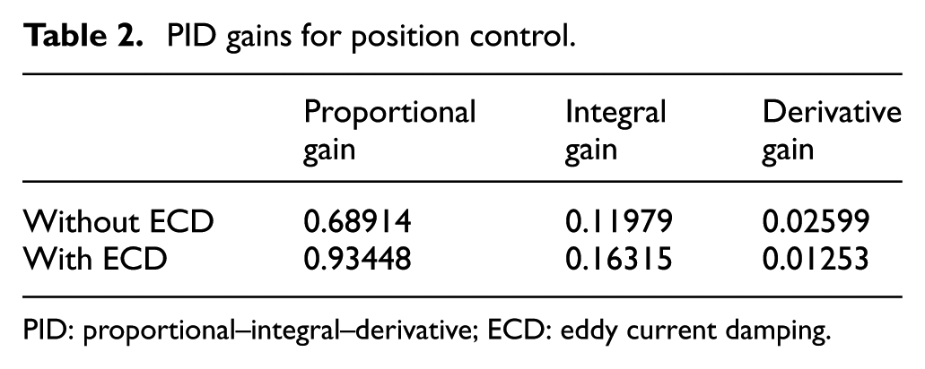
PID: proportional–integral–derivative; ECD: eddy current damping.
Experimental verification
Step response
The step signals were inputted and the responses were compared to verify the effect of the proposed ECD module, as shown in Figure 12. The air gap in the ECD module used in the test was 23 mm. The comparisons of the overshoot and settling time (within 0.5% of the input value) are presented in Table 3 before and after the application of the ECD. The same rise time (0.65 s) and transient behavior were applied to the systems for a fair comparison of the cases with and without ECD. When the ECD was applied, the overshooting was nearly the same because the same transient setting was used. If the same PID gains are set, surely the overshoot will be reduced when applying the ECD module compared with the case without the module. However, the settling time was reduced by 36.8% before (0.57 s) and after (0.36 s) the application of the ECD. The damping and natural frequency of the system, including the PID controller, were calculated through the step response test, as presented in Table 4. When a different controller was used, the natural frequency, damping, and spring constants can be altered. 19 However, when the ECD was used and the damping effect was added, there was minimal change in the natural frequency and spring constant. Using the 1-µm step response test, as shown in Figure 13, the resolution of the system was improved by 59.4%: 1.7 µm without ECD, but 0.69 µm with ECD.
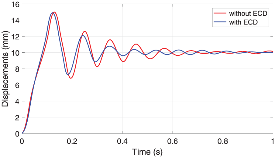
Comparison of step responses.
Overshoot and settling time of step response.
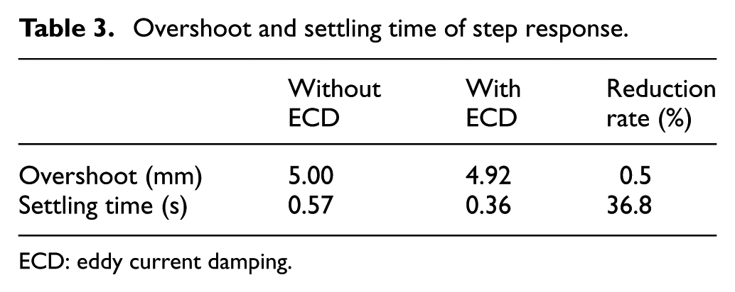
ECD: eddy current damping.
Identified system parameters from experiments.

ECD: eddy current damping.
1-µm step responses.
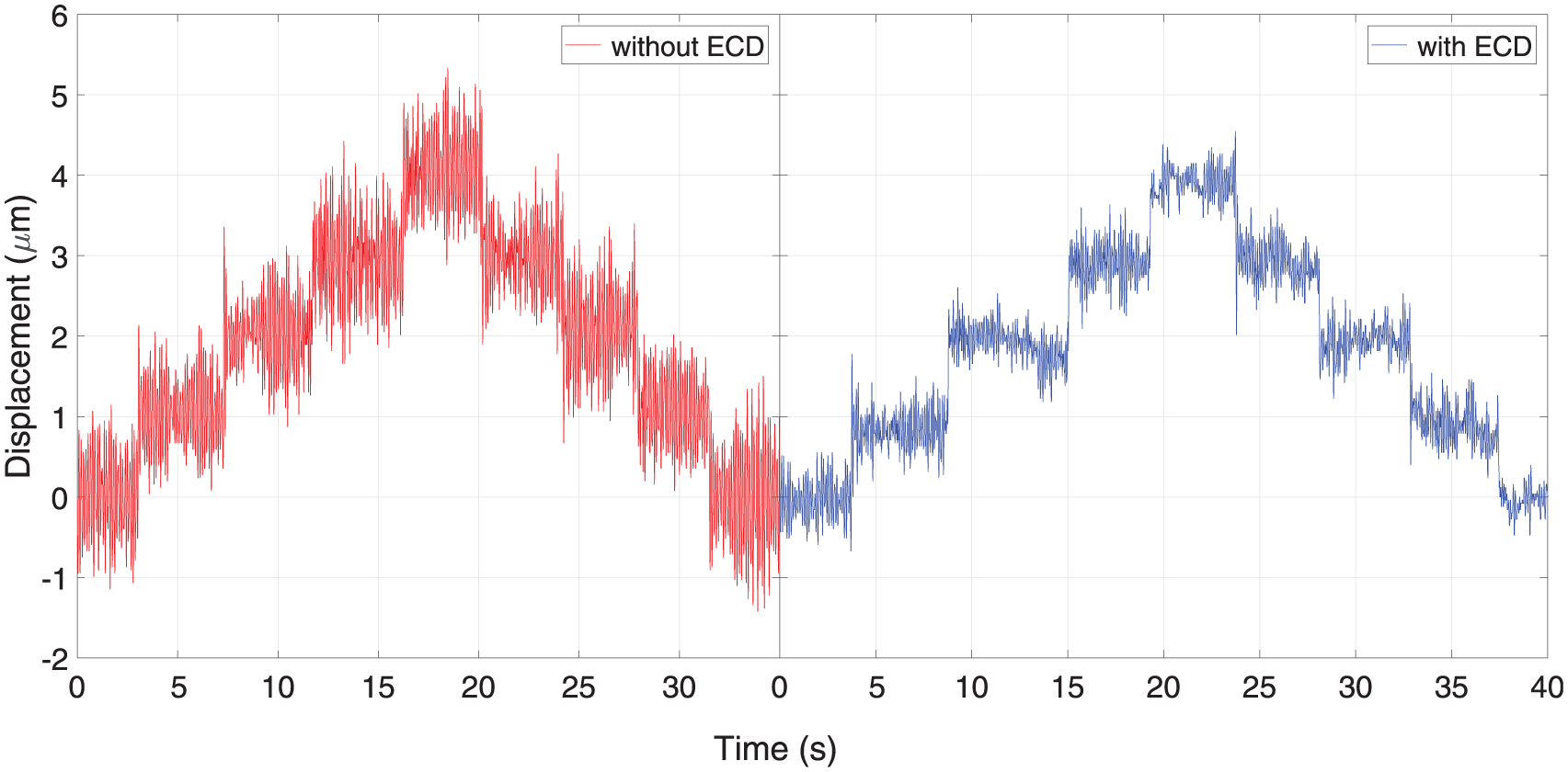
In-position stability
To verify whether the problem of the low in-position stability of air bearings and linear motors can be overcome in the designed positioning system, the stability was observed for with and without ECD while maintaining the position. In Figure 14, we show the response to disturbance while keeping a set position when the designed PID controller was applied. The difference between the maximum and minimum points showed a reduction of 23% before (2.6 µm) and after (2 µm) the application of the ECD in the time domain. The standard deviation was reduced by 47.5% before (0.366 µm) and after (0.192 µm) the application of the ECD.

In-position stability, with and without ECD, for the (a) time domain and (b) frequency domain.
The response also was reduced in the frequency domain, with a reduction of 66.2% at 8.7 Hz and by 52.2% at 12.6 Hz. These two frequencies are the vibration of the system from air fluctuation and the jig’s flexibility, respectively. This result verifies that the in-position stability of the system improved when the ECD was applied.
Conclusion
In this study, we proposed using ECD to improve the positioning capability of a system using air bearings and a linear motor. This enables precise positioning by overcoming the low damping of the system without contact. The designed ECD module provides advantages over the LM system because it operates in a noncontact state, while providing additional damping effects. The module was configured using a Halbach array of permanent magnets to maximize the damping force, based on the theoretical principles of the eddy current. The additional damping force in the designed ECD was characterized experimentally. The damping coefficient variation according to the speed was expressed as an equation, and the simulations were carried out to design a controller for the positioning system.
A reduction in the settling time of 36.8% after the application of the ECD was verified, while the same rise time was maintained through the step input experiments in the positioning system, which was configured by adding the designed controller. Applying a PID controller for fair comparison, the natural frequency and spring constant only changed slightly. On the contrary, only the damping effect can be increased while maintaining other system characteristics using the ECD. Because of these characteristics, the resolution of the system was also improved, by 59.4%. For the in-position stability experiment, the performance was also improved. This was verified in the time domain, resulting in a reduction of the standard deviation by 47.5%. In the frequency domain, the observed undesired responses were reduced for all ranges of frequencies; in particular, there was a reduction of 66.2% at 8.7 Hz and 52.2% at 12.6 Hz. These two frequencies are the system resonances. Based on the above results, the improved in-position stability using ECD was verified. When the air bearing moves with high speed, the effect of dynamic air bearing makes the damping nonlinear, and further study is needed.
The ECD proposed in this study can overcome the low damping of systems configured with air bearings and linear motors. A positioning system with improved damping performance has more precise positioning and deceleration capabilities. If ECD is applied to a semiconductor or display manufacturing process, where high precision is required, ultra-precision production can be achieved, resulting in an improved production process.
Footnotes
Handling Editor: James Baldwin
Declaration of conflicting interests
The author(s) declared no potential conflicts of interest with respect to the research, authorship, and/or publication of this article.
Funding
The author(s) disclosed receipt of the following financial support for the research, authorship, and/or publication of this article: This material is based upon work supported by the Ministry of Trade, Industry & Energy (MOTIE, Korea) under Industrial Technology Innovation Program. No.20000665, Development of eco-friendly and highly durable surface treatment for superomniphobic substrate on the large area over 4 m2.