
Abstract
A model of photovoltaic-electrostatic cantilever beam based on lanthanum-modified lead zirconate titanate ceramic is proposed in this article. New equivalent electrical model of lanthanum-modified lead zirconate titanate ceramic connected to a parallel plate composed of two copper foils is obtained by modifying the original lanthanum-modified lead zirconate titanate equivalent electrical model. After that, the mathematical model of photovoltaic-electrostatic cantilever beam is established. Furthermore, the influences of ultraviolet light intensity and copper foil length on the deflection of the photovoltaic-electrostatic cantilever beam are analyzed via the theoretical and experimental methods. The analysis results indicate that the deflection at the free end of cantilever beam increases with the increase in light intensity and length of the copper foil. The photovoltaic-electrostatic flexible cantilever beam can be taken as a micro-actuator with the advantages of remote control and clean drive.
Keywords
Introduction
Micro-cantilever beam is a very common structure in micro-mechanical system, and it is commonly used in inertial sensors and actuators. Microelectromechanical system cantilever beam switches are playing a very significant role in developing the word of miniaturization while maintaining the required qualities of switches. 1 The common driving methods are electrostatic drive, thermal drive, electromagnetic drive, and piezoelectric drive. Because of its simplicity and low power consumption, electrostatic drive is most widely used in micro-mechanical system. For example, the microelectromechanical system cantilever switches induced by electrostatic force are used in a variety of portable electronics and radio frequency telecommunications systems. 2 However, the traditional electrostatic drive powered by an external power supply is susceptible to electromagnetic interference. In the clean operating space and vacuum, traditional electrostatic drive has great limitations. With the development of smart materials, the emergence of new type of actuators and the breakthrough in key technology has been greatly promoted. Lanthanum-modified lead zirconate titanate (PLZT) ceramic can generate kilovolt between the two electrodes when exposed to 365 nm ultraviolet (UV) light, so that UV light can be used instead of an external power source as a driving source. Compared with the driving mode of the external power supply, the light driving technology has the advantages of clean driving, no electromagnetic interference, noncontact remote light control, and wireless energy transmission, and it is an ideal driving mode of cantilever beam.
In the past few decades, many scholars conducted a series of researches on the theory and engineering application of PLZT ceramic. In 1979, Fridkin 3 proposed the resistor–capacitor (RC) electrical model of PLZT ceramic along the polarization direction. In 2000, Poosanaas et al. 4 pointed out that the optical secondary nonlinearity is an important cause of the anomalous photovoltaic effect. In the 1980s, Sada et al. 5 designed the photo-driven relay and the photo-driven micro-walking machine based on the photostrictive effect of the PLZT bimorph. In 1996, Tzou and Chou 6 proposed a two-dimensional photostrictive actuator and applied it in vibration control for rectangular plate. In 2004, Ichiki et al. 7 designed an electrostatic-optical motor based on the photovoltaic effect of PLZT. In 2005, Shih et al. 8 investigated a photostrictive constitutive model of PLZT with coupling opto-piezo-thermo-elastic fields. In 2007, Li et al. 9 designed a light-controlled servo system and pointed out that improving the response speed of PLZT is the key to promote its engineering application. In 2009, Luo and Tong 10 applied 0–3 polarized PLZT ceramic to the active control of the photoelectric laminated beam. In 2011, they studied shape morphing of laminated composite structures with photostrictive actuators via topology optimization. 11 Wang 12 studied the driving ability of different size actuators. Zheng 13 conducted a coupled multi-physics modeling of 0–3 polarized PLZT ceramic and carried out the finite element simulation. Wang et al. 14 carried out the experiments on the response characteristics of PLZT ceramic. Wang et al. 15 illustrated a novel optical driving mechanism with PLZT multi-patches combination, which is more suitable for the distributed optical driving systems.
For the photovoltaic effect of PLZT ceramic, many scholars have studied the theory and applied it to active shape and vibration control of beam, plate, and shell structure. Shih et al. 8 combined the experimental data of Fukuda et al. to deduce the constitutive equations of PLZT ceramic in 2005, but failed to consider the effect of thermal expansion on the photo-induced electric field. In 2015, Huang et al. 16 considered the effect of thermal expansion on the photo-induced electric field and proposed a model for predicting photo-induced voltage and photo-induced deformation based on the coupling of multiple fields. In 2011, Rahman and Nawaz 17 carried out modeling analysis of optical actuator based on PLZT ceramic. He et al.18,19 conducted the active vibration control of photostrictive thin cylindrical shells structure. Jiang et al. 20 investigated the vibration control of cylindrical shells with a hybrid photovoltaic/piezoelectric actuation mechanism. Wang et al. 21 proposed closed-loop control of cantilever beam based on hybrid photovoltaic/piezoelectric actuation mechanism. These studies provide a theoretical fundamental for the photovoltaic-electrostatic driving on the basis of PLZT ceramic.
In this article, the equivalent electrical model of PLZT ceramic with external load is deduced, and the mechanics model of photovoltaic-electrostatic cantilever beam via the micro-element method is obtained. Then, the relationship between the PLZT photovoltage and the deflection at the end of cantilever beam is investigated. After that, the theoretical analysis of the influence factors on the deflection of the cantilever beam is carried out. Finally, the established mathematical model and theory are verified through experiments.
Mathematical modeling of the photovoltaic-electrostatic cantilever beam based on PLZT ceramic
Photovoltaic-electrostatic cantilever beam
Photovoltaic-electrostatic cantilever beam structure is illustrated in Figure 1. It consists of PLZT ceramic photoelectric transducer, ultraviolet light source, noncontact displacement sensor, high impedance electrostatic voltmeter, flexible cantilever beam, and computer. When PLZT ceramic is irradiated vertically by the ultraviolet light with a wavelength near 365 nm, the photo-generated carriers flow along the polarized direction, so that the positive electrode and the negative electrode of the PLZT ceramic collect the positive and negative charges, respectively, to generate a high photovoltaic voltage of several kilovolt per centimeter. The silver wire is used to connect the electrodes of the PLZT ceramic to the two pieces of copper foil, which are attached to the cantilever beam and the fixed base, respectively, with the insulating adhesive. Because the two pieces of copper foil collect the same amount of charge with the opposite polarity, the two copper foils attract each other under the action of electrostatic force to generate a driving force, thereby causing deflection of the cantilever beam.

The schematic diagram of the photovoltaic-electrostatic cantilever beam.
Mathematical modeling of the photovoltaic-electrostatic cantilever beam
When a PLZT ceramic is irradiated by ultraviolet light, high photovoltaic voltage is generated between the electrodes of the ceramic, as a result of the anomalous photovoltaic, pyroelectric, photothermal, and piezoelectric effects. The photovoltage responds dynamically with illumination time until it reaches saturated voltage. At this time, the PLZT ceramic can be considered as a parallel circuit consisting of a photo-current, a photo-resistor RP, and a capacitor CP, 22 and the equivalent electrical model is shown in Figure 2.
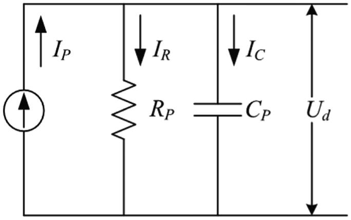
Equivalent electrical model of PLZT ceramic.
The photovoltage between the electrodes of PLZT ceramic can be written as

where IP is the photo-current, IR is the current flowing through the resistor, IC is the current flowing through the capacitor, τ is the time constant, and Us is the saturated photovoltaic voltage.
When the two electrodes of the PLZT ceramic are connected to a parallel plate composed of two pieces of copper foil, part of the photo-generated carriers are conducted between the copper foils using air as a medium, and part of them are stored on the two copper foils in the form of charges. Hereby, equivalent electrical model of electrostatic parallel plate driven by PLZT ceramic is presented in Figure 3. Ra and Ca are the resistance and capacitance of the parallel plate generated by two parallel copper foils, respectively.

Equivalent electrical model of electrostatic parallel plate driven by PLZT ceramic.
According to the above-mentioned new equivalent circuit model, the driving voltage produced by PLZT ceramic for electrostatic parallel plate is

where τ′ is the new time constant and the expression is
The length, width, and thickness of the cantilever beam are assumed as l, b, and h, respectively, while the length and width of the copper foil are assumed as lcu and bcu (bcu = b), respectively. The thickness of the copper foil is negligible herein.
Take an infinitesimal dx of cantilever beam as shown in Figure 4, and it can be approximated as a micro-parallel-plate capacitor in this situation. d is the initial distance between the two copper foils and dw is the deflection at the infinitesimal dx of cantilever beam.

The schematic diagram of infinitesimal dx of cantilever beam.
The internal energy of this micro-parallel plate is obtained as
where
Based on the principle of virtual work, the infinitesimal electrostatic force of the micro-parallel plate capacitor can be presented as
According to equation (5), dF is related to the dielectric constant
As shown in Figure 5, the deflection w(x) at any point x of the cantilever beam when subjected to the force F is given by 23

where a is the distance between the point of force F and the fixed end of the cantilever beam, Y is Young’s modulus of the cantilever beam, and I is the inertia moment of the cantilever beam.
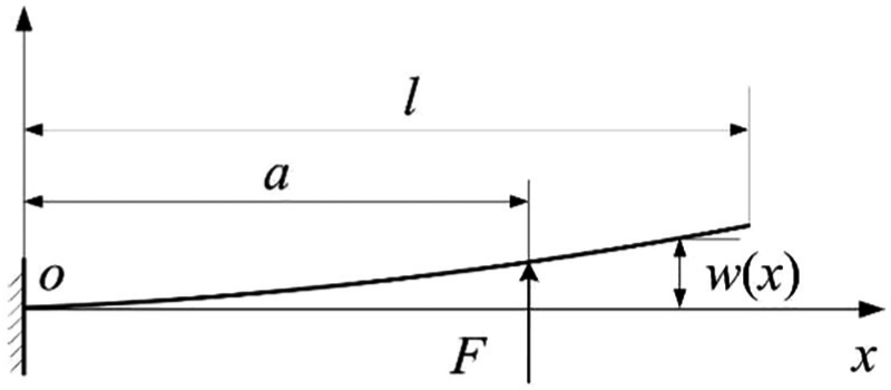
Deformation diagram of cantilever beam subjected to force F.
For x = l, that is, the free end of cantilever beam, when subjected to infinitesimal electrostatic force dF generated by infinitesimal dx, the deflection at the free end of cantilever beam dwtail can be written as

Substituting equation (5) into equation (7), one can get another expression of the deflection at the end of cantilever beam dwtail. Since the deflection dw at any position of electrostatic area and wtail at the free end of cantilever beam are much smaller than the initial distance d, replacing the deflection dw with the deflection wtail gives simplified equation as

Equation (8) shows the deflection at the free end of cantilever beam due to an infinitesimal electrostatic force dF acting on the x = a point of cantilever beam. For the entire cantilever beam, numerous infinitesimal parallel-plate capacitors which have their own infinitesimal electrostatic forces dF together to make the end of cantilever beam generate bending deformation. The deflection at the free end of cantilever beam generated by each infinitesimal electrostatic force dF satisfies equation (8). The analytical solution of the deflection can be obtained by using the superposition property, which is suitable for the elastic beam with small deflection.
Replacing a by x yields the corresponding dwtail, that is, the deflection at the free end of cantilever beam generated by infinitesimal electrostatic force dF is shown as
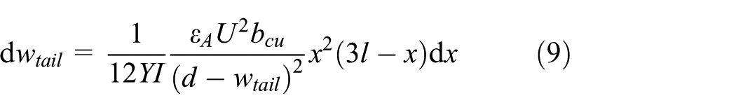
Sorting out equation (9), differential equation about cantilever beam driven by electrostatic force can be obtained. Integrating the two sides of the equation generates an integral equation as

Considering the boundary conditions wtail = 0 when lcu = 0, the deflection wtail at the end of cantilever beam can be rewritten as

Substituting equation (2) into equation (11), the relationship between the PLZT photovoltaic voltage and the deflection at the free end of cantilever beam can be rewritten as

It can be seen from equations (11) and (12) that the deflection wtail at the free end of cantilever beam is related to the driving voltage Ud produced by PLZT ceramic, the material parameters Y and I of the cantilever beam, the length l of the cantilever beam, the dielectric constant
Experimental validation of influencing factors of photovoltaic-electrostatic cantilever beam
The size of the PLZT sample used in this experiment is 10 mm (LP) × 5 mm (WP) × 1 mm (TP). The cantilever beam is made of poly(methyl methacrylate) (PMMA) and has dimensions of 100 mm (L) × 5 mm (W) × 1 mm (T), and Young’s modulus of it is 3 GPa. The inertia moment of the cantilever beam is 4.17 × 10⁻¹³ m4.
The experimental platform of photoelectric electrostatic driving flexible cantilever beam is shown in Figure 6. When irradiated by UV light, PLZT ceramic generates photovoltage on the basis of the anomalous photovoltaic effect. With the influence of the electrostatic force between the two copper foils, the deflection of the cantilever beam is generated, which is measured by a noncontact displacement sensor (STIL Initial 12), whose axial resolution with average 10 and the maximum linearity error are 500 nm and 180 nm, respectively. Meanwhile, the voltage between the two copper foils is measured by a high-impedance electrostatic voltmeter (Trek Model: 821HH), whose measurement range is 0 to ±2 kV direct current (DC), and the accuracy is better than ±1% of full scale at the voltage monitor output.

Experimental platform of photoelectric electrostatic driving flexible cantilever beam.
Influence of ultraviolet light intensity on the deflection at the end of cantilever beam
It can be seen from the relevant reference that when the size of PLZT ceramic is unchanged, the number of photo-generated carriers within the PLZT ceramic will increase with the increase in the light intensity. The macroscopic appearance is due to the increase in photo-current IP. 2 The relationship between photo-current and ultraviolet light intensity can be described as

where
When the PLZT ceramic is connected to the parallel plate structure, according to the equivalent electrical model of Figure 3, it shows that the saturated driving voltage of PLZT ceramic is still determined by the product of the photo-current IP and equivalent resistance
In the experiment, the distance between the copper foils d is 4 mm and the length lcu and the width bcu of the copper foil is 20 mm and 5 mm, respectively. When the UV light intensity is 50, 100, and 200 mW/cm2, the curves of the photovoltaic voltage without load and with load varying with time are tested.
Figure 7 shows the comparisons of photovoltaic voltage without and with copper foil load at 50, 100, and 200 mW/cm2, respectively. It can be seen from Figure 7 that as the UV light intensity gradually increases from 50 to 200 mW/cm2, both the photovoltaic voltage without and with the load increases. However, the photovoltaic voltage with load is slightly lower than that without load, and the trend is basically the same. This is due to the resistance Ra of the parallel copper foil which is about 8 × 10¹⁴ Ω and calculated based on the dimensions of the copper foil and the air conductivity of 5 × 10⁻¹⁴ S/m, which is larger than the PLZT photo-resistor RP (about 1013−1012 Ω). Depending on the characteristics of the parallel circuit shown in Figure 3, the saturated photovoltaic voltage with load

Comparison of photovoltaic voltage without and with copper foil load under various light intensities: (a) light intensity is 50 mW/cm2, (b) light intensity is 100 mW/cm2, and (c) light intensity is 200 mW/cm2.
As can be seen from Figures 1 and 7, the voltage measured by the high-impedance electrostatic voltmeter is actually generated by the charge accumulated on one of the two copper foils. Therefore, the driving voltage measured by the high-impedance electrostatic voltmeter should be doubled and then substituted into equation (12) to get theoretical values. Comparisons between the theoretical and the experimental deflection curves are obtained in Figure 8. It can be seen from Figure 8 that the theoretical deflection curves meet well with the experimental deflection curves measured experimentally, and both increase with the increase in UV light intensity.

Comparisons of theoretical and experimental deflections with various light intensities: (a) light intensity is 50 mW/cm2, (b) light intensity is 100 mW/cm2, and (c) light intensity is 200 mW/cm2.
Influence of copper foil length on the deflection at the end of cantilever beam
When the UV light intensity is constant at 200 mW/cm2, all the other influencing factors remain the same except for the copper foil length lcu. The theoretical steady-state curve of the deflection at the end of cantilever beam varies with copper foil length lcu, which is given in Figure 9.

Theoretical steady-state curve of the deflection at the end of cantilever beam over copper foil length.
As can be seen from Figure 9, the corresponding theoretical steady-state deflection wtail will increase gradually as the copper foil length lcu increases slowly from 0 to the cantilever beam length l. The closer the length of the copper foil lcu to the length of the cantilever beam l, the smaller the change rate of the steady-state deflection wtail.
Figure 10 shows the comparisons of the photovoltaic voltage without copper foil load and the photovoltaic voltage with the copper foil length lcu of 10, 15, and 20 mm, respectively. It can be seen that the photovoltaic voltage without load and with different copper foil loads under 200 mW/cm2 UV light intensity is coincident with each other basically, which is consistent with the previous analysis.

Comparison of the photovoltaic voltage without copper foil load and the photovoltaic voltage with different copper foil loads.
Figure 11 shows the theoretical and experimental deflection curves when the copper foil lengths are 10, 15, and 20 mm, respectively. Taking experimental error into consideration and other basic conditions, it can be seen from the following curves that the experimental curve meets well with the corresponding theoretical curve.

Comparison of theoretical and experimental deflection curves with different lengths of the copper foil: (a) comparison of deflection curves of lcu = 10 mm, (b) comparison of deflection curves of lcu = 15 mm, and (c) comparison of deflection curves of lcu = 20 mm.
Figure 12 is a comparison of the deflection at the end of cantilever beam corresponding to different lengths of the copper foil. It can be seen that the larger the length of the copper foil, the greater the deflection, which is consistent with the trend described in Figure 8.

Comparison of deflection curves for different lengths of the copper foil.
Conclusion
In this article, a type of photovoltaic-electrostatic driving method based on PLZT ceramic is proposed. With equivalent electrical model of PLZT connected to a parallel plate composed of two copper foil pieces, the mechanism of the photovoltaic-electrostatic driving is mathematically modeled and the relationship between the photovoltaic voltage of PLZT ceramic and the deflection at the free end of photovoltaic-electrostatic cantilever beam is established. The influence factors (i.e. light intensity and the length of the copper foil) on the deflection at the end of the photovoltaic-electrostatic cantilever beam are analyzed via theoretical and experimental method. The results show that the deflection at the free end of photovoltaic-electrostatic cantilever beam increases with the increase in light intensity and the length of the copper foil. Furthermore, as the resistance of the parallel copper foil is much larger than the photo-resistor of PLZT ceramic, the photovoltages of PLZT ceramic without and with different copper foil load are nearly unchanged. The experimental deflection curves meet well with the corresponding theoretical deflection curves. So, the rationality of the mathematical model is verified in this article.
Since light energy is the initial input and the micro-displacement is one of the outputs, the photovoltaic-electrostatic flexible cantilever beam can be taken as a micro-actuator with the advantages of remote control and clean drive. Of course, the deflection response of the photovoltaic-electrostatic flexible cantilever beam actuator should be improved if it is applied to a fast micro-drive, which will be studied in our next research stage.
Footnotes
Handling Editor: James Baldwin
Declaration of conflicting interests
The author(s) declared no potential conflicts of interest with respect to the research, authorship, and/or publication of this article.
Funding
The author(s) disclosed receipt of the following financial support for the research, authorship, and/or publication of this article: The authors gratefully acknowledge the funding support from the National Natural Science Foundation of China (No.51675282) and Jiangsu Overseas Visiting Scholar Program for University.