
Abstract
All-terrain cranes with multi-axles have large inertia and long distances between the axles that lead to a slower dynamic response than normal vehicles. This has a significant effect on the dynamic behavior and steering performance of the crane. Therefore, the purpose of this study is to develop an optimal steering control algorithm with a reduced driver steering effort for an all-terrain crane and to evaluate the performance of the algorithm. For this, a model predictive control technique was applied to an all-terrain crane, and a steering control algorithm for the crane was proposed that could reduce the driver’s steering effort. The steering performances of the existing steering system and the steering system applied with the newly developed algorithm were compared using MATLAB/Simulink and ADAMS with a human driver model for reasonable performance evaluation. The simulation was performed with both a double lane change scenario and a curved-path scenario that are expected to happen in road-steering mode.
Keywords
Introduction
All-terrain cranes, the most typical example of mobile construction equipment, have an excellent lifting capacity and the capability to operate both off-road and on-road. However, its large inertia and long axle-distance slow down the dynamic response during steering, and its high center of mass can cause rollover. Hence, a technology to improve the steering performance needs to be developed. Various studies regarding the steering control of mobile construction equipment, including the all-terrain crane, are being actively carried out.
Wang et al. 1 proposed a proportional control strategy by using zero side-slip angles at the mass center and by evaluating the steering performance of a heavy vehicle with three axles in different steering modes. A multi-mode steering control scheme using a cross-coupled control was developed to improve the steering accuracy of a large-scale transportation vehicle. 2 A self-tuning proportional–integral–derivative (PID) control with fuzzy logic was presented for an electro-hydraulic steering system of a multi-axle crane. 3 In the research of Noh et al., 4 turning stability was studied for a multi-axle steering vehicle by means of the Ackerman theory in the case of a high-speed running mode. Qin et al. 5 developed a multi-bridge steering system for an all-terrain crane. In their study, a hydraulic model and a multi-body model for a multi-bridge steering system were designed using AMESim and ADAMS software, respectively. Gao and Li 6 proposed a novel steering algorithm for a multi-axle vehicle by combining the traditional Ackerman steering and the Skid steering method, and explored the turning characteristics. Zhang et al. 7 developed a novel fuzzy observer-based steering control algorithm for path tracking in autonomous vehicles. The effectiveness of the proposed fuzzy observer-based output feedback controller was evaluated in Carsim/Matlab joint simulation environment. Cao et al. 8 proposed a new vehicle path-following strategy of the steering driver model using general predictive control method. The purpose of the proposed active steering control algorithm by the authors is to assist the driver to follow the desired path efficiently. The algorithm was evaluated in some typical conditions such as strong crosswind in standard double lane change.
However, the above studies were based on the existing PID control, Ackerman theory, and observer-based control, and the purpose of the studies generally focused on improving the desired path tracking performance of the vehicles. In addition, the previous studies did not consider the driver’s steering effort to affect the driver’s fatigue while driving.
Therefore, this study proposes a steering control strategy that considers the driver’s characteristics in order to improve the steering performance (reducing steering effort of driver) of a 120-ton (maximum lifting capacity) all-terrain crane with multiple axles. For this, a simplified crane model for the crane steering system was derived in terms of lateral and yaw dynamics, and its error dynamics were modeled. Moreover, the optimal steering control algorithm that would reduce the driver’s steering effort was developed using a model predictive control (MPC) technique. To evaluate the developed control algorithms, a virtual steering input of human driver was computed using a predictive human driver model with the MPC technique with the assumption that the road information can be obtained from a sensor such as camera for obtaining errors for feedback control. Then, a co-simulation linked with both MATLAB/Simulink and ADAMS was performed under the scenarios of a double lane change and a curved path in road-steering mode. Based on the analysis results, the steering system applied with the proposed algorithm and the existing steering system were compared from the perspective of steering effort and dynamic stability.
The article is organized as follows. “Conventional steering principle for all-terrain crane” section describes a conventional steering principle for an all-terrain crane. “Modeling of an all-terrain crane steering system” section describes the modeling of the steering system. “Design of a human driver model” section describes the design of the human driver model. “Design of control algorithm” section describes the design of the steering control algorithms. “Evaluation of steering performance” section describes the evaluation of the steering performance. Finally, concluding remarks are provided in the “Conclusion” section.
Conventional steering principle for all-terrain crane
The conventional steering principle for existing all-terrain cranes is as follows. As the motion of the second of a crane is mechanically constrained by the first axle, the steering angle at the second axle is subject to that of the first axle (i.e. the driver’s steering input angle). The relationship between these steering angles is provided in Figure 1 and equation (1). The steering angles at the third, fourth, and fifth axles are independently determined according to the steering mode and driving speed of the crane.

Correlation between the steering angles of the first and second axle.
Typical steering modes include the all-wheel steering mode, the road-steering mode, the crab steering mode, the reduced swing-out mode, and the independent steering mode. Among these, the road-steering mode is used for general driving on public roads

where

Ackerman theory–based steering strategy of the third, fourth, and fifth axles at various speeds in road-steering mode.
As it can be seen in the Figure 2, the third axle was designed to be fixed for all velocity conditions in the conventional steering principle of actual cranes. This is to ensure driving safety by creating a large turning radius from the axles that are fixed by speed, because a larger lateral acceleration occurs even at a small yaw rate as the speed increases. Figure 3 shows the correlation between the steering angle at the first axle and those at the third, fourth, and fifth axles at various driving speeds in road-steering mode.

Relationship between steering angle at the first axle and those at the third, fourth, and fifth axles in road-steering mode: top: 0–30 km/h, middle: 30–60 km/h, bottom: >60 km/h.
This article proposes a steering strategy that improves the steering performance of an all-terrain crane and reduces the driver’s steering effort in road-steering mode.
Modeling of an all-terrain crane steering system
Simplified model for a multi-axle crane steering system
In this study, a simplified steering system model for an all-terrain crane with five axles (Figure 4) was derived to analyze its lateral motion using a bicycle model that has been widely used for an analysis of vehicle dynamics (lateral, yaw, side slip, etc.), controller design, and control performance evaluation. Several assumptions applied for the mathematical model derivation are listed as follows:
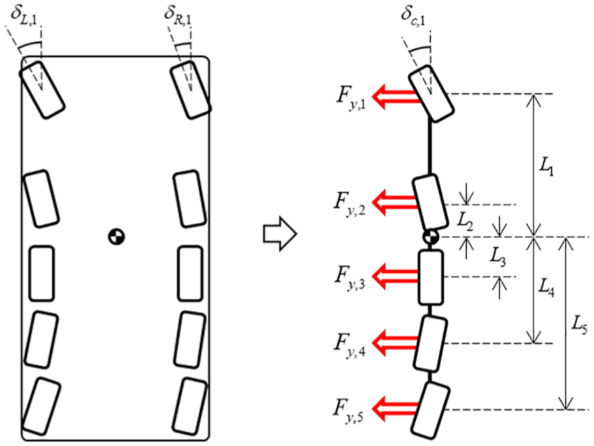
Simplified modeling of a crane using a bicycle model.
Assumptions for mathematical modeling of a crane steering system are as follows:
Longitudinal speed is constant.
Body slip angle is sufficiently small.
Left slip angles are identical with right slip angles.
As the figure illustrates, both wheels at each axle of the crane are represented by a single wheel on the center line of the axle.
In the figure,

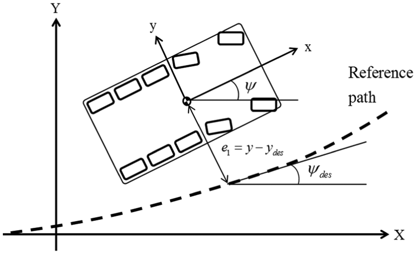
Based on the formula above, the state and the state-space model showing the lateral and yaw dynamics of the crane are given in equations (3) and (4)–(6), respectively 9
where y and

where

where

where
Error dynamics for steering control
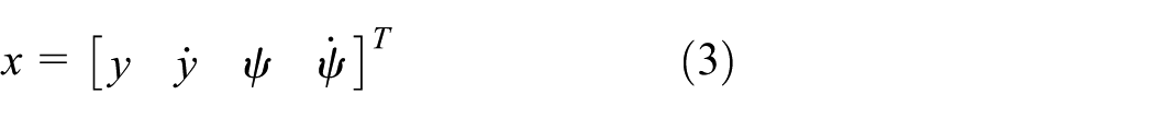
Information about the state error (i.e. the lateral and yaw angle errors), as shown in Figure 5 and equations (7) and (8), is necessary for the design of a steering control algorithm.
Lateral and yaw angle errors for error dynamics.
The X–Y and x–y coordinates described in Figure 5 are the crane’s global and local coordinates, respectively. The local coordinate is based on the mass center of the crane. The term e1 represents the lateral displacement error (i.e. the difference between the lateral position


The state vector e for error dynamics with e1 and e2 is as follows

where

where R is the radius of curvature. As the rate of curvature change in public driving roads is not sufficiently large, the desired yaw rate

where
Design of a human driver model
In order to conduct reasonable performance evaluation of the steering control algorithm virtually, the human driver model should be used. Therefore, the predictive driver model was used for performance evaluations in this study and the steering input from the human driver model was considered as an actual human driver for evaluation of the driver’s effort. In general, a driver displays three steering characteristics while driving. First, the steering input is applied after perceiving the vehicle’s preview information and state. Second, the steering input applied here is a prediction-based input. Third, the update frequency of steering input with the changing environment varies with the proficiency and sight of the driver. The driver’s steering characteristic about time delay (time delay characteristic is realized by update frequency) is one of the most important characteristic caused by brain response and neuromuscular system. In this study, the update frequency is defined as 0.1 s. In this study, the human driver model has been used to conduct reasonable performance evaluation of the steering control algorithm developed. Figure 6 shows the driver’s steering input behavioral characteristics.

Driver’s steering behavior.
In the figure, a preview distance

In the driver model, the lateral error

Lateral and yaw angle errors for the driver model.
Also, the lateral error and yaw angle error were computed using the tangent line on a reference path near the preview point. The dynamics of these errors can be defined as below


where
The error dynamics derived above,

Structure of the MPC-based steering control system.
The error states in equation (13) have been used for the human driver model and steering model because the purpose of the steering control algorithm is to reduce the driver’s steering effort for steering efficiency (the error states used for the human driver model also have been used for the steering model). The steering model described in Figure 8 needs more states such as derivatives of
Design of control algorithm
Structure of the control system
The steering control algorithm proposed in this study uses a model predictive human driver model to derive the realistic human driver’s steering angle of the first axle. Specifically, the steering angles at the third, fourth, and fifth axles were computed according to the human driver’s input using MPC algorithm (however, the steering angle at the second axle was determined by the driver’s input based on equation (2)). In addition, the error dynamics and the MPC algorithm are used to derive the optimal steering angles of the third, fourth, and fifth axles, which allow individual steering. Figure 8 shows the structure of the MPC-based steering control system.
As illustrated in the figure, the MPC-based steering control system consists of error calculation models for the driver model and steering model, the MPC-based driver model, the MPC-based steering model, and the crane model. The steering map shows the relationship between the steering angles at the first and second axles. The crane model was designed using a full three-dimensional (3D) multi-body model in the ADAMS environment, and was used to evaluate the steering and dynamic performances.
In the case of the MPC-based driver model, the value of
The purpose of the above control strategy is to reduce the steering effort by minimizing the driver’s steering input. The control algorithm was designed in the Matlab/Simulink environment.
MPC technique
The MPC algorithm derives the current optimal input based on prediction. This algorithm performs a prediction by regarding the current state as an initial plant value within the finite prediction time horizon, which is used to solve an optimal problem of the finite horizon open-loop system. Unlike the existing control methods that apply a pre-calculated result, the MPC algorithm derives a real-time optimal solution online. This optimal solution can be derived by applying the constraint to every input and state. 16 Figure 9 shows the concept outline of an MPC.

MPC concept.
Using these characteristics of MPC, this study develops a control algorithm to obtain the optimal value of
MPC formulation for obtaining an optimal value of
based on the driver model
The objective function of the MPC algorithm to derive the scalar optimal value of


where

where the matrices
By rearranging equation (16) with equation (18), the quadratic objective function can be expressed as shown in equation (19)

The optimal solution

where a and b determine the decrease ratio of

where
MPC formulation for obtaining an optimal values of
for the steering system
The MPC algorithm to derive the optimal values of

where

where

where the matrices

The optimal solution
Evaluation of steering performance
The performance of the developed steering control algorithm was evaluated in the ADAMS environment. A double lane change and a curved path (radius of gyration: 90 m), which frequently occur in road-steering mode, were selected as the scenarios for evaluation. Figure 10 shows each selected scenario.

Double lane change (left) and curved path scenario (right).
Simulations were performed with the driving speed conditions of 28, 50, 72 km/h, which represent three speed ranges in road-steering mode (see Figure 2). Based on the analysis results, the steering performances of both the proposed steering control system and the conventional steering system were compared and analyzed.
As conditions for the simulation, the preview time

where t is the simulation time and
Simulation setup in ADAMS environment
The steering control algorithm proposed in this study uses a human driver model and a MPC algorithm to derive the optimal steering angle.
A 3D multi-body crane model modeling in ADAMS environment
A typical mechanical system consists of many components. ADAMS is a multi-body dynamics analysis software that simulates and analyzes the dynamic behavior of mechanical systems according to the time change. The information regarding the behavior of components connected with joints under kinematic conditions of large displacement, including not only the position of each component according to the time change, velocity, acceleration, and joint reaction but also the natural frequency of the system, mode shape, and state-space matrix, can be acquired through a multi-body dynamic analysis using ADAMS. Moreover, kinematic, static, and quasi-static analyses of a mechanical system, as well as linear, non-linear, and dynamic analyses, are all possible.
Based on the CATIA design of the mobile crane to be developed, a dynamic model was configured for the main components related to the vehicle dynamics by using the ADAMS. The configured dynamics model can be largely divided into two parts: the top and bottom structure of the vehicle. The vehicle’s bottom part consists of each steering axle, the engine, the body, the tires, and so on. Because most of the components of the bottom structure can affect the vehicle’s steering performance, the dynamic model was configured using an actual model. The top structure of the vehicle was configured using a concentrated mass (Figure 11).

Dynamic model of all-terrain crane.
Figure 12 illustrates a schematic diagram of the co-simulation in which the Matlab/Simulink-based control system and the ADAMS-based multi-body dynamics analysis model of the crane are linked together for their simultaneous operation like a single system. While the yaw rate, position, and velocity were set as the output variables of the ADAMS model in the figure, the steering angles for each axle was set as the input variables of the ADAMS model that are computed from the Matlab/Simulink model. The x and y positions of the center of mass, yaw angle, longitudinal velocity, and lateral velocity of the crane are sent to Matlab/Simulink every 0.01 s. The steering angle of each axle is then calculated at 0.01 s intervals using the transmitted data in the Matlab/Simulink-based control system, and is sent back to ADAMS.
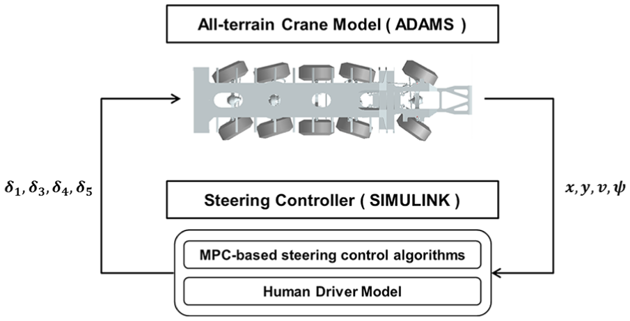
Co-simulation between ADAMS and Simulink models.
Simulation results
Case 1: double lane change scenario
In the double lane change scenario, the simulation conditions for the driving time and driving distance per driving speeds are shown in Table 1.
Conditions for driving time and driving distance per driving speeds in double lane change scenario.
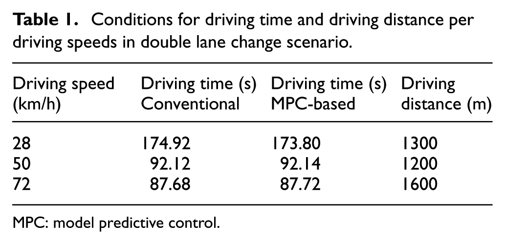
MPC: model predictive control.
Figures 13 and 14 and Tables 2 and 3 show the simulation results of the steering angle and steering effort.

Steering angle and steering effort in double lane change: (a) velocity: 28 km/h, (b) velocity: 50 km/h, and (c) velocity: 72 km/h.

Dynamic behavior in double lane change: (a) velocity: 28 km/h, (b) velocity: 50 km/h, and (c) velocity: 72 km/h.
Steering effort comparison in double lane change scenario.

MPC: model predictive control.
Dynamic behavior comparison (angle (°), rate (°/s)).

MPC: model predictive control; Con: convention system.
The simulation result shows that in the double lane change scenario, the driver’s steering input of the MPC-based steering system can be significantly reduced by steering assistance at the third, fourth, and fifth axles. Moreover, although the dynamic states (yaw rate, roll angle, and roll rate) of the crane in the MPC-based steering system can be stabilized compared to the existing system, the roll angle and rate at 72 km/h, as well as the roll rate at 50 km/h, have relatively large values. This is because the steering control system is not optimized with consideration of the driver’s driving intention (i.e. various driving characteristics for individual drivers). Nevertheless, it was confirmed that the proposed MPC-based steering system efficiently reduced the driver’s steering effort compared to the existing system on a comprehensive level, and that its dynamic stability could be improved in all conditions except for the roll angle and rate at 72 km/h, as well as the roll rate at 50 km/h.
Case 2: curved path scenario (R = 90 m)
In the curved-path scenario with the radius of gyration being 90 m, the simulation conditions for the driving time and driving distance per driving speeds are shown in Table 4.
Conditions for driving time and driving distance per driving speeds in curved-path scenario with radius of gyration of 90 m.
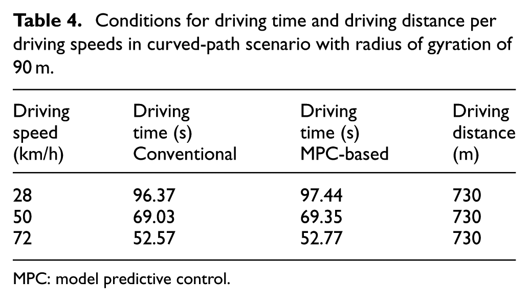
MPC: model predictive control.
Figures 15 and 16 and Tables 5 and 6 show the simulation results.

Steering angle and effort in curved path: (a) velocity: 28 km/h, (b) velocity: 50 km/h, and (c) velocity: 72 km/h.

Dynamic behavior in curved path: (a) velocity: 28 km/h, (b) velocity: 50 km/h, and (c) velocity: 72 km/h.
Steering effort comparison in curved path scenario.
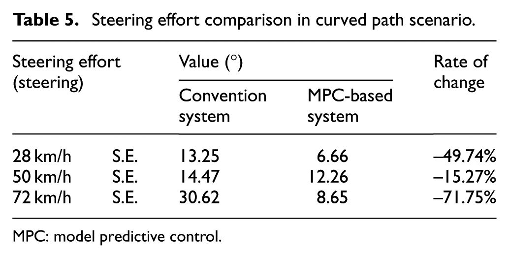
MPC: model predictive control.
Dynamic behavior comparison (angle (°), rate (°/s)).

MPC: model predictive control; Con: convention system.
The MPC-based steering system proposed in the curved-path scenario can effectively reduce the driver’s steering effort. However, the yaw rate was relatively high at speeds of 50 km/h or less, and the values for roll rate and angle were slightly higher in the MPC-based system except for the roll angle at 72 km/h and the roll rate at 50 km/h, although no significant difference was observed between the two systems. On a comprehensive level, the proposed MPC-based steering control system revealed a better performance compared to the existing steering system, as the proposed MPC-based steering system could effectively reduce the driver’s steering effort, and showed the dynamic stabilization almost equivalent to that of the existing steering system at the same time. Considering the different driving characteristics among drivers, however, it can be determined that an optimized control algorithm must be applied in order to reasonably reflect the driving intentions of the driver.
Conclusion
The purpose of this study is to develop an optimal steering control algorithm that can reduce a driver’s steering effort for an all-terrain crane, and to evaluate the performance of the developed algorithm with a human driver model. A bicycle model was used to derive a simplified model for a crane steering system. A MPC-based control algorithm was applied to derive the optimal steering angle for each axle. The performance of the control algorithm developed in the Matlab/Simulink environment was evaluated with the human driver model through co-simulation with the crane dynamics model developed in the ADAMS environment. The performance verification was carried out for double lane change and curved-path scenarios at various speeds (28, 50, and 72 km/h) in road-steering mode.
In the co-simulation configuration where the ADAMS-based dynamics model and Matlab/Simulink-based control system were interconnected, the vehicle’s position, velocity, and yaw information were set as the output variables for the ADAMS model. Moreover, the steering angle of each axle was also set as an input variable for the ADAMS model that was calculated by the MPC-based control algorithm with the Matlab/Simulink. Here, the time step for co-simulation was set to 0.01 s.
The analysis results confirmed that the MPC-based steering system effectively reduced the driver’s steering effort compared to the existing steering system, and that the dynamic stability (yaw rate, roll angle, and roll rate) of the existing steering system for a crane can be secured in the proposed system. However, because the driving characteristics are different for individual drivers, the development of an optimized steering control system reflecting specific driving characteristic (e.g. steering angle rate by applying inequality constraints to the MPC) is considered as future work. Since driver’s intention was not considered in the proposed steering control algorithm, the driving stability of a crane may not be secured in double lane change scenario due to conflicts between control inputs and driver’s inputs in a practical system. Therefore, the proposed steering control algorithms can be extensively developed by incorporating the driver’s driving intention (i.e. driver’s unique driving characteristics) as a future work, which can improve the performance of both vehicle stability and steering controls through predictions of driver’s input with the MPC algorithm. For example, the MPC algorithm may compute optimal steering inputs by predicting the driver’s inputs based on the driver’s intention. Furthermore, it is planned as future works to develop multiple constraints of the MPC for improving the yaw and roll stability of the crane while reducing steering efforts because the steering control algorithm proposed in this study does not consider stability.
In this study, it was assumed that the desired yaw rate is close to zero. However, the desired yaw rate is not close to zero if the crane is driving on a winding road. Therefore, the MPC technique needs to be improved by including an additional component that enables to deal with non-zero desired yaw values and thus to enhance the steering control performance.
The proposed MPC-based steering control algorithm for reducing a driver’s steering effort can be applied extensively to various multi-axle vehicles including cranes. The steering control algorithm developed in this study can be implemented in an actual crane using steering angle sensors (encoders) and cameras to improve driving stability and steering efficiency. It is expected that the simulation and analysis techniques developed in this study can also be utilized for the design phase.
Footnotes
Appendix 1
Appendix 2
Handling Editor: Long Cheng
Declaration of conflicting interests
The author(s) declared no potential conflicts of interest with respect to the research, authorship, and/or publication of this article.
Funding
The author(s) received no financial support for the research, authorship, and/or publication of this article.