
Abstract
This article presents a sphere–face gear pair by substituting the convex spherical gear for the pinion of a conventional face gear pair. The sphere–face gear pair not only maintains the advantages of the face gear pair with a longitudinally modified pinion but also allows variable shaft angles or large axial misalignments. Meshing characteristics of the proposed gear pair are studied in this article. The mathematical models of the sphere–face gear pair are derived based on machining principles. The tooth contact analysis (TCA) and curvature interference check are conducted for the sphere–face gear pair with variable shaft angles. The loaded TCA is also implemented utilizing the finite element method. The results of numerical examples show that proposed gear pair has the following features. Geometrical transmission error of constant shaft angle or varying shaft angle is zero; contact points of the sphere–face gear set with variable shaft angle are located near the centre region of face gear tooth surface; there is no curvature interference in meshing; and transmission continuity of the gear pair can be guaranteed in meshing.
Keywords
Introduction
The face gear drive is composed of a cylindrical pinion and a bevel gear. It is more capable of handling larger reduction ratios than the bevel gear drive because of its geometry. The main advantage of such a gear drive is the possibility of splitting the torque and the reduction in weight.1–3 Localization of the contact (point contact) is needed to prevent edge contact and separation of tooth surfaces, which may occur with the presence of misalignment errors. Therefore, the face gear is usually generated by a shaper with an increased number of teeth relative to the pinion. To improve the performance of face gear drives, several modification approaches of tooth shapes have been put forward. Litvin 4 presented the gear drive that contains a helical face gear and a conventional involute helical pinion. The bearing contact path of the face gear in this design is directed vertically. Transmission error of misalignment or alignment is zero. Litvin et al. 5 developed an asymmetric face gear drive with asymmetric profiles and a double-crowned pinion of the drive. Control of the position and orientation of the contact path can be achieved by adjusting the machine tool settings of the pinion. Tooth contact analysis (TCA) and stress analysis showed good results in terms of sensitivity to misalignments and stress levels. Zanzi and Pedrero 6 proposed an enhanced approach for manufacturing a double-crowned gear by introducing a tilt of the plane that contains the planar trajectory performed by the centre of the disc during generation. This double-crowned gear was then applied in the face gear drive. TCA and stress analysis demonstrated that an appropriate choice of machine tool settings can produce better contact patterns without a high reduction in the contact ratio. Shen et al. 7 studied a new modified face gear drive with a double-crowned helical pinion shaped by a parabolic rack cutter and a plunging grinding disc. The numerical simulation results indicated that the face gear drive is not sensitive to misalignment errors. Fang et al. 8 provided a new type of face gear drive with intersected axes, which was composed of a spiral bevel face gear and a cylindrical pinion with lengthwise curved teeth. They came to the conclusion that the concave and convex of face gear tooth surfaces can enhance gear strength. Cui et al. 9 employed a fabrication method to form an imaginary gear for the arc tooth face gear drive. Then, a numerically controlled machining model was established by transforming adjustment parameters from the cutter-tilt milling machine to a common multi-axis numerical control machine. Lin and colleagues10–12 presented an orthogonal fluctuating gear ratio face gear pair, which comprises a non-circular pinion and a curve–face gear. Based on the mathematical model, they investigated the undercutting and pointing conditions, tooth contact and transmission errors of the curve–face gear pair.
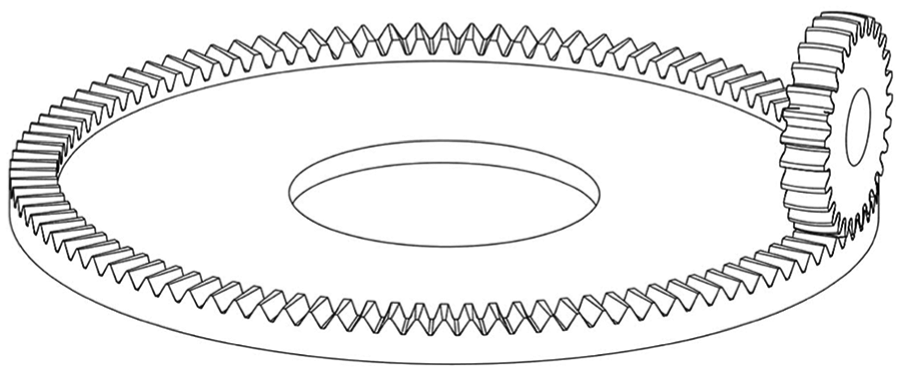
Mitome et al. 13 brought forward the spherical gear drive and provided its machining method. This gear pair consists of the gear with convex teeth and the one with concave teeth. The convex spherical gear is similar to the gear with drum teeth in the drum tooth coupling. However, their manufacturing approaches are different. The convex spherical gear can mesh conjugately with a cylindrical involute gear. 14 Since a cylindrical involute gear and a face gear constitute a face gear pair, the convex spherical gear may mesh with a face gear conjugately. Thus, a new face gear pair called a sphere–face gear pair is obtained. As the pitch surface of the convex spherical gear rolls on the pitch plane of the face gear, the sphere–face gear set allows variable shaft angles or larger axial misalignments without gear interference in meshing. In addition, it maintains the inherent properties of the normal face gear pair with a longitudinally modified pinion. With the purposes of studying the feasibility of this new face gear drive and understanding its meshing characteristics, mathematical models are derived, the curvature interference is checked, and unloaded and loaded TCAs with variable shaft angles are implemented.
Mathematical models of sphere–face gear pair
Mathematical model of convex spherical gear
As depicted in Figure 1, to generate a convex spherical
13
gear, there are two feed motions as follows: the axial feed of the hob (the velocity is denoted as

Hobbing method of convex spherical gear.

Conical surface generating convex spherical gear.
As displayed in Figure 3, the imaginary rack cutter tooth surface

where

Coordinate systems for rack cutter.

Normal profile of imaginary rack cutter.
Similarly, the formula for the arc

where
To simulate the generation of tooth surfaces, several coordinate systems are created, as shown in Figure 5, where

Coordinate systems for generation of a convex spherical gear.
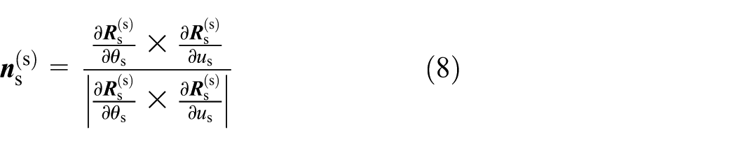
According to the transformation relation, the unit normal vector for

In the light of theory of gearing, the meshing equation for the convex spherical gear and rack cutter can be expressed as follows

where
The position vector and unit normal vector for


where
Mathematical model of face gear
Suppose

where

Tooth surface of an involute gear cutter.
For generating the tooth surface of a face gear, the following coordinate systems are defined as displayed in Figure 7.

Coordinate systems for generation of a face gear.
The unit normal vector of
The meshing equation for the face gear and gear cutter can be expressed as follows

where
The position vector and unit normal vector of


where
TCA
Mathematical model
According to the aforementioned procedure, tooth surfaces of a sphere–face gear pair can be constructed. The three-dimensional (3D) models may then be built as shown in Figure 8. To study the distribution of contact points, the TCA needs to be implemented. Figure 9 displays the coordinate systems for TCA.
Meshing of a convex spherical gear and a face gear.
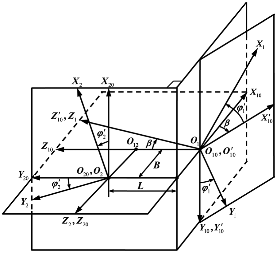
Coordinate systems for a sphere–face gear pair.
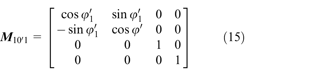
In this figure, parameter


where
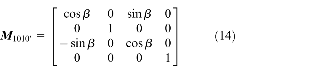


The TCA equations are shown as follows

The aforementioned system has five independent variants. Given the input parameter

where
Example
Design parameters for a sphere–face gear pair are provided in Table 1. The TCA is performed in two cases (Case A:
Design parameters for a sphere–face gear pair.

Results of TCA in Case A.

TCA: tooth contact analysis; TE: transmission error.
Results of TCA in Case B

TCA: tooth contact analysis; TE: transmission error.
Contact paths on tooth surfaces: (a) convex spherical gear and (b) face gear.
For Case A, it can be seen from Table 2 that both
Curvature interference check
Condition
Proper meshing of two tooth surfaces with each other can be realized only when there is no curvature interference at their contacting points. Whether there is curvature interference at any meshing contact is subject to the signs of induced normal curvatures of engaged surfaces. Specifically, if the induced normal curvature is negative, there is no curvature interference.
As displayed in Figure 11,

where
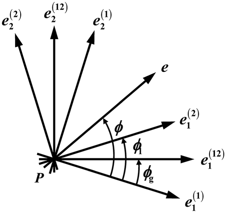
Principle directions for principle curvatures of
Let

The solutions for equation (21) are
Example
According to the results in Table 2, the principle-induced normal curvatures are computed as the pinion rotates. The results are displayed in Figure 12. As the pinion rotates,

Induced normal curvatures of
Loaded TCA
Finite element model
Based on the parameters in Table 1, a five-tooth quasi-static finite element model is built using the commercial code ABAQUS. The main material properties are defined as follows: the elastic modulus is 210 GPa and Poisson’s ratio is 0.3. As shown in Figure 13, the reference points are created on the axis of the pinion (convex spherical gear) and the gear (face gear), respectively. Nodes on the inner surfaces are coupled with the respective reference points, and the torque and the constraints are also applied to the reference points. A torque (1000 Nm) is imposed on the face gear, whose rotational degree of freedom is released. An angular displacement constraint (1 rad) is applied to the pinion with five restricted degrees of freedom. A contact pair is defined between the engaged gears. C3D8R (linear refined element) is used to mesh gears, as shown in Figure 14. When

Coupling relations with reference points.

Mesh of sphere–face gear pair.
Results and analysis
Figure 15(a)–(e) show the contact stress nephograms of the face gear when

Contact stress nephograms: (a)
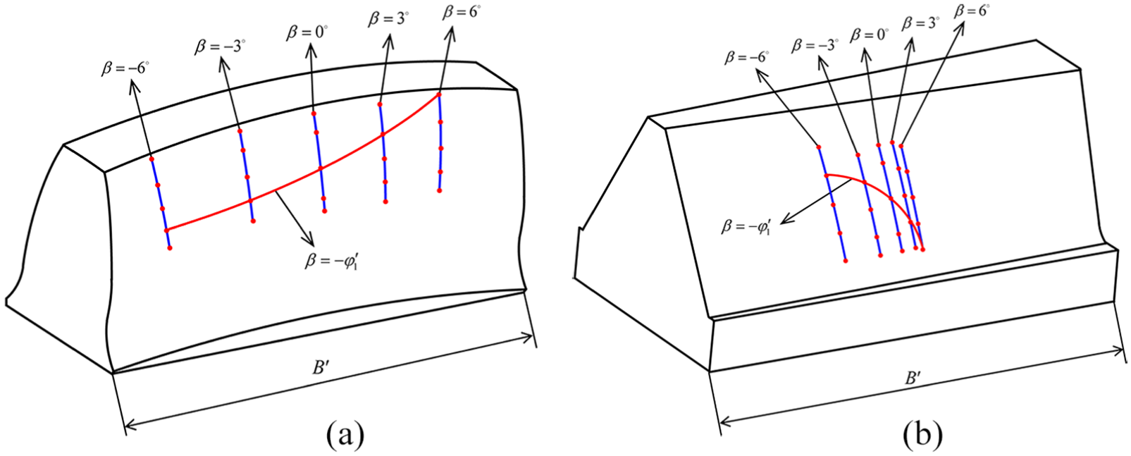
Figure 16 shows the loaded transmission error of the sphere–face gear pair. When
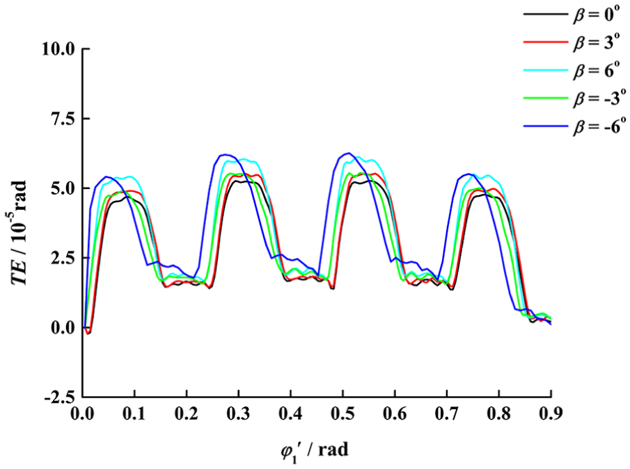
Loaded transmission error.

Peak–peak values of loaded transmission error.
Figure 18 demonstrates the normal contact forces of three consecutive tooth pairs at

Normal contact forces for three consecutive tooth pairs.
Conclusion
In this study, a sphere–face gear pair is proposed with the pinion of a convex spherical gear. To investigate its meshing characteristics, the mathematical models of the gear pair are established, the curvature interference in meshing is checked, and unloaded and loaded TCAs with variable shaft angles are performed. The simulated results of the numerical examples have the following conclusions:
The meshing of the sphere–face gear set is in point contact. Although the variation in shaft angle affects the location of contact area of sphere–face gear pair, the contact points are located near the centre region of face gear tooth surface, indicating that there is no edge contact for the sphere–face gear set with variable shafts or axial misalignments.
Whether the shaft angle varies or not, the geometrical transmission error of the sphere–face gear set is exactly equal to zero. There is no curvature interference in meshing with the variable shaft angle, and the convex sphere gear can mesh with the face gear properly.
Loaded TCA results show that the distribution of contact points is similar to that of TCA, and shaft angle affects the maximal contact stress.
The transmission accuracy and continuity can still be guaranteed in meshing, even considering elastic deformation.
Footnotes
Handling Editor: Farhad Ali
Declaration of conflicting interests
The author(s) declared no potential conflicts of interest with respect to the research, authorship and/or publication of this article.
Funding
The author(s) disclosed receipt of the following financial support for the research, authorship and/or publication of this article: This work was supported by ‘the Fundamental Research Funds for the Central Universities’ (grant no.: NS2016049).