
Abstract
Analysis of the Chongqing monorail shows that there is no relationship between wheel wear and radial force, which means the radial force cannot be used to evaluate the wheel wear of monorail. Due to the same physical significance of the Schallamach tire wear model for automobiles, the wear index of railway wheels, which represents the creep power of unit wheel–rail contact area, is proved to be effective in evaluating the wheel wear of railway vehicles, automobiles, and vehicles with both properties, namely, monorail. Parameters of Chongqing monorail, modified through genetic algorithm, are used to build the model of the articulated monorail. Through co-simulation of the MATLAB and UM software, the wheel wears of two types of articulated monorail are calculated. For both types of monorails, correlation analysis shows that the variation of driving wheel and guide wheel wear of the inner bogies with the track curvature radius are roughly the same. The variation of the wheel wears in the two end bogies is a little different from that of the inner bogies. Comparison indicates that the wheels of the bolster type monorail wear more than that of the non-bolster type. Regardless of the monorail type, the wheels in the inner bogies wear more.
Keywords
Introduction
The wheel, one of the most important components of vehicle, has been widely paid attention to. Wheel wear is a major problem that must be solved promptly.
Wear function, considering the energy dissipated in the contact patch of rail and wheel surface with a worn material, is used to measure the wheel wear in many researches. Three wear regimes, severe wear, mild wear, and catastrophic wear, are defined in this function. The analytical formula for wear rate is given in Tao et al., 1 Lewis and Dwyer-Joyce, 2 and Lewis et al. 3 It expresses weight loss in the material per distance rolled per contact area. C Wirtz et al. 4 focused on the research of the effect of the cemented carbide specification on the grinding wheel wear. According to the phenomenon of the thermo-mechanical load collective and the grinding wheel wear, the wear mechanisms and the influence of the cemented carbide specification on the wear behavior of the grinding wheel could be obtained. S Pradhan et al. 5 and Li et al. 6 assumed that the wear depth is symmetric around the wheel periphery. Because slip is 0 in the adhesion region, it is only needed to calculate the wear in the slip region. Due to its results’ reasonably closeness to experiments, Archard’s wear model was set up. He put emphasis on the wear distribution of the wheel by taking the effects of traction into account, braking and curving on a real track segment. A Shebani and Iwnicki 7 set up a NARXNN model for wheel/rail wear prediction. S Prinz et al. 8 and Klocke et al. 9 built a quantitative model of grinding wheel wear and extended the investigations to further grinding wheel and formed roller specifications so as to guarantee the wide applicability of the model. C Feldmeier 10 built a wear model through a procedure to estimate the slip distribution in the contact patch. Kalker’s simplified slip prediction theory is used in his article. Material loss caused by wear is predicted on the base of the dissipative energy of the creep force along with creepage.11,12 ML Wu 13 carried out a simulation for the wear life characterization of the grinding wheel during electrolytic in-process dressing (ELID) grinding by a moving normal distribution curve of the grit state variation. Enblom 14 mentioned two predictive wear models used in the railway system. The first one assumes that material loss of the wheel is proportional to frictional energy dissipated. The second one is built according to the principle of Archard’s wear model. The material loss is thought proportional to the product of normal force and sliding distance and inversely proportional to the material hardness. Tunna et al. 15 and Pombo et al. 16 found good agreement between the energy dissipation wear models and the Archard wear model. Many researchers evaluate and predict wear according to the proportionality between the amount of worn material and the frictional energy dissipation.11,16–20 In previous studies,21–26 Archard’s wear model is considered to be a prevalent wear prediction model in the tribology community to model sliding wear.
It is known that articulated train, which has been invented for several years, has a good curve negotiation performance. However, no similar study of monorail regarding this aspect has been conducted. Monorail is a special type of rail vehicle, uses rubber tires. The dynamic properties of monorail are not completely the same as rail vehicles and automobiles. The wheel wear formula has not been unified in the standard. The aim of this article is to systematically analyze the wear of articulated monorail wheels
Research objectives
The objectives of this article are as follows:
Establishment of the wheel wear model of monorail. Using FIALA formula, the wheel force model is set up. Then it is proved that the formula which has been used to evaluate the wheel wear of the railway vehicles could also be used to evaluate the tire wear of monorail.
Some misunderstandings in the calculation of monorail wheel wear. It is proved that the radial force could not be used to evaluate the wear of the monorail guide wheel.
Modeling of the articulated monorail. First, the parameters of the traditional monorail are modified with the experiment. Using the parameters, the dynamic models of the two kinds of articulated monorail are finally set up.
Co-simulation model for the wear index of monorail wheels.
Result analysis, including the comparison of the wheel wear between the two kinds of monorails and comparison of the wheel wear of different bogies in the same monorail. Correlation analysis is also carried out in the comparison.
Vehicle model of traditional monorail
The articulated monorail, introduced by a patent, 27 is in the manufacture process. The vehicle of articulated monorail should be modified by traditional monorail. Single straddle type monorail vehicle includes one car body and two bogies. The constraints of the car body and bogies are provided by the secondary suspension system composed of the air spring and viscous damper. Because of the multidirectional elasticity of the rubber tire, there is no primary suspension system. The running gear and the track beam are constrained by four guide wheels, two stable wheels, and four driving wheels.
The car body has 6 degrees of freedom. The air spring is the secondary suspension system between the car body and the bogie frame. The bogie frame also has 6 degrees of freedom as the car body. There are traction rubbers, shock absorbers, longitudinal and lateral stops between the center pin and the bogie frame which play a function of transmitting power and vibration.
Thus, the vehicle model of 20 degrees of freedom is established in the UM software, as shown in Figure 1

Tire models
Tire is an important part of the monorail.31,32 HL Chang et al. 33 built the three-dimensional models of all the tire’s component, and the finite element analysis was done for the vehicle–bridge–coupling system. Because the mechanical properties of rubber material are complicated, Z Du et al. 34 divide the tire into three parts: inner tube, tire casing, and cushion belt. The finite element models of the running tire and the pre-stressed concrete (PC) track beam were built. However, T Hitoshi 35 simplified the tire as a spring to benefit for calculation. To benefit both calculation and high accuracy, FIALA tire model is chosen for calculation.
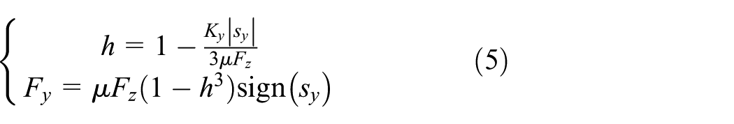
According to FIALA tire model, the equation of the tire side force can be shown as follows

Case 1

Case 2

where

Case 1
Case 2

where
Wheel wear model of the monorail
As a special type of rail vehicle, monorail uses rubber tires. The dynamic properties of monorail are not completely the same as rail vehicles or automobiles. As a result, the wheel wear formula has not been unified in the standard.
For railway vehicles, wear index commonly used in the United States, Canada, and other countries to measure wheel–rail wear degree is shown in equation (7) 36
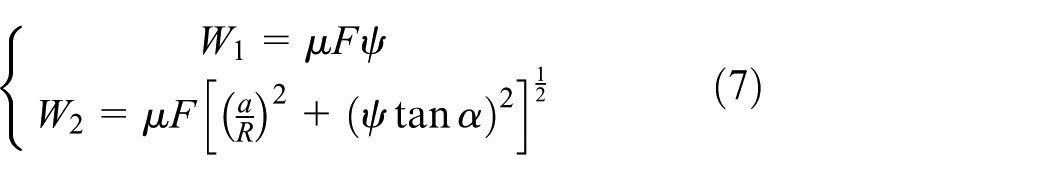
In rail vehicle system,
Since the monorail wheel and rail surface are not contacted in two points, the second formula cannot apply to monorail. Besides, for the monorail wheel, there is no flange angle or attack angle; therefore, the first formula is not applicable to monorail, either.
However, there are also some places using wear index W shown in equation (8) to describe the degree of wheel wear regardless of the wheel shape 36

The physical significance of this formula is the creep power of unit wheel–rail contact area regardless of the wheel shape.
For automobile tires, according to the hypothesis of Schallamach, the distribution of contact pressure

It is defined

Let

In this equation, the cornering stiffness is

Input them into equations (11) and (12) could be obtained as follows

Similarly, the longitudinal wear energy can be obtained as follows
The longitudinal stiffness of the tire is defined as follows

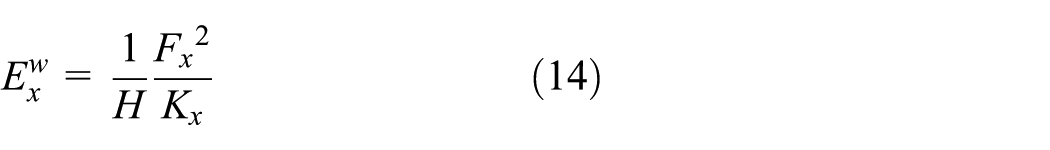
The total wear energy of the unit area when the tire rolls one circle could be defined as follows

The unit area wear energy of unit distance of tire rolling can be shown as follows

R is the radius of the tire.
On the other hand, the wear energy formula can be deduced according to the creep force working theory.
Set the velocity of the vehicle as V, the rotation angular velocity of the tire as w, and the rotation time for one circle as t. The following equations can be obtained
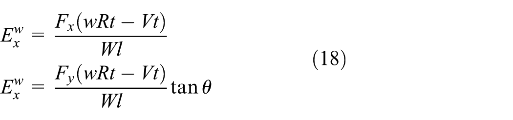
The unit area wear energy per unit distance of tire rolling can be shown as follows

The wheel wear equation without Kalker index for the railway vehicles is shown as follows.
Analysis in this paper shows the method to evaluate the wheel wear of rail vehicles could also be adopted to evaluate the tire wear of automobiles. That means this formula could be used in the monorail having owns the properties of both rail vehicles and automobiles.
Some misunderstandings in calculation of monorail wheel wear
At present, there is no standard for calculating the wheel wear of monorail. For expedience, in some engineering calculations, the radial force of the guide wheel is used to evaluate the wear of the guide wheel. It is considered that the greater the radial force of the guide wheel is, the more the wheel wears.
However, according to the previous wheel wear formula, the monorail wheel wear is defined as the wear power in unit contact area. With the increase of the wheel radial force and wheel radial compression, the contact area between tire and rail surface will broaden, and wheel wear will not certainly increase.
Taking the Chongqing straddle monorail as an example, the comparison of the wear index and the radial force of the guide wheel is as follows. Numbers 1–6 substitute for the left, right stable wheel, the front left, front right, rear left, and rear right guide wheel of the bogie, respectively.
It can be seen from the figure that the radial force of the guide wheel is not directly proportional to the wear index, so the radial force of the guide wheel cannot be used to evaluate the wear of the guide wheel in the following analysis.
Parameter modification
In his research, J Zhou 38 mentioned that the monorail simulation results are in good agreement with the experimental data when the America sixth spectrum is used to calculate the road irregularities in the study. Consequently, the irregularities of the America sixth track are adopted in this research.
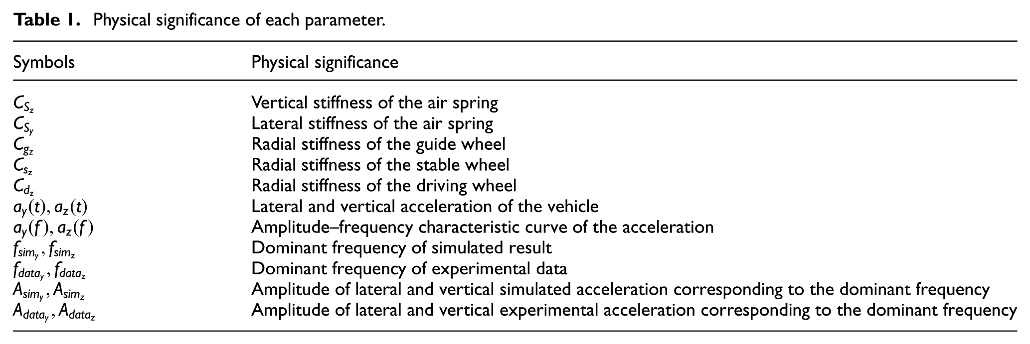
To test the curve negotiation performance, parameters of the articulated monorail are obtained by the parameters of real monorail. Due to aging, wear, and process errors of the rubber components, the actual parameters of rubber components are different from the set values. These parameters are modified with the experimental data (Table 1).
Physical significance of each parameter.

The modification step is shown in Figure 2. Genetic algorithm is used in the process of parameter modification.

Comparison of the wear index and the radial force of the guide wheel: (a) the front bogie and (b) the rear bogie.
As shown in Figure 3, after parameter modification, the simulation results are in good agreement with the experimental data as mentioned in Jiang et al. 29 From the above analysis, it can be inferred that the simulation model can replace the experimental vehicle for the next analysis (Figure 4).

Process of parameter modification using genetic algorithm.
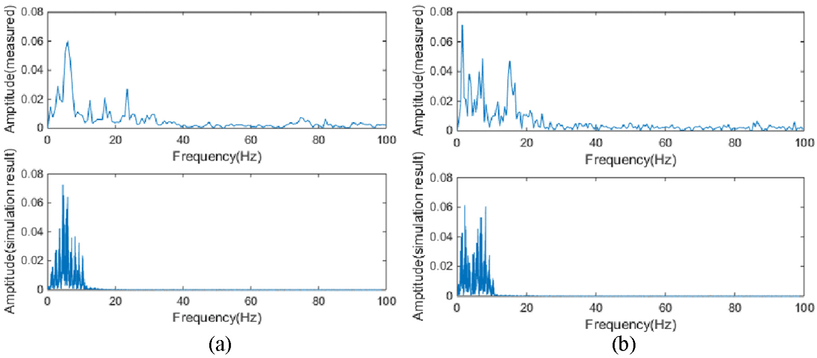
Amplitude–frequency response of vehicle acceleration: (a) lateral acceleration and (b) vertical acceleration. 29
Structure of the articulated monorail
Different from the traditional monorail, the head and tail vehicle of articulated monorail own a bogie, respectively, and inner adjacent vehicles share one bogie. The advantage of the articulated structure is to reduce the number of bogies greatly.
According to the traditional classification, articulated vehicles are mainly divided into bolster type and non-bolster type. 39 In this article, these two articulated monorail models are set up, and the articulated bogie structure is shown in Figure 5.

Structure of the articulated bogie: (a) articulated bogie of non-bolster type and (b) articulated bogie of bolster type. 29
For articulated bogie of non-bolster type, the coupler is connected with two adjacent carriages, and four air springs are mounted on the articulated bogies. The front two are connected with the front car, and the rear two are connected with the rear one. The articulated bogie structure with a bolster is approximately the same as the traditional straddle type monorail bogie. The couplers of the front and rear carriages are articulated on the bolster, respectively. The bolster is mounted on the air spring of the articulated bogie. The six car models of the two kinds of articulated monorail are obtained and shown in Figure 6.

UM model of the articulated monorail: (a) non-bolster type and (b) bolster type. 29
Co-simulation model for the wear index of monorail wheels
Professor Gim and Nikravesh40–42 who has laid the foundation of the UA tire model said the contact area of the tire and the road surface can be assumed to be rectangular. The contact area length l of UA model is shown as follows

Since in general

Area of contact surface, the following equation can be obtained

H is the tire width. As for road vehicle, the radial stiffness of the tire is defined as follows

Longitudinal slip ratio can be shown in equation (26)
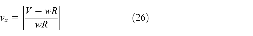
V denotes the speed of the vehicle. w is the rolling angular velocity of the tire. Lateral slip ratio is shown in equation (27)

Let matrix
FDz(i, j), FDy(i, j), FDx(i, j) respectively substitute for the radial, side, and longitudinal force of the number j driving wheel on the number i bogie; wD(i, j), the angular velocity of the number j driving wheel of the number i bogie;
Let matrix
FGz(i, j), FGy(i, j), FGx(i, j) respectively substitute for the radial, side, and longitudinal force of the number j guide wheel (stable wheel) of the number i bogie. wG(i, j), the rolling angular velocity of the number j guide wheel (stable wheel) of the number i bogie.
Set the vector of the bogie’s rolling angle as

As for guide wheel and stable wheel, the camber angle of the wheel is equal to the bogie’s pitching angle. It can be shown in equation (29)

As for driving wheels, the wear index of the number j driving wheel on the number i bogie

In the equation, HD is the width of the driving wheel; RD is the radius of the driving wheel; CDz is the radial stiffness of the driving wheel.
As for guide wheels (stable wheels), the wear index of the number j guide wheel on the number i bogie
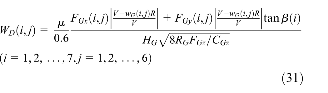
In UM software, the vehicle dynamics equations are calculated by Park method. Through the co-simulation of MATLAB and UM software, the wear indexes of the wheels are calculated. The flow chart is shown in Figure 7.
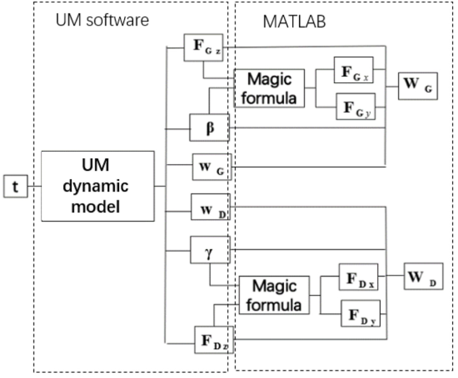
Flow chart of the tires’ wear indexes.
Comparison of the wheel wear for two types of monorail
It is known that at any time t, there is a wear index for a wheel. In order to compare wheel wear of each monorail, the mean wear indexes of each wheel are obtained.
When the monorail passes a right-side curve, figures can be obtained as follows. In the figures, Project 1 substitutes for the bolster type monorail, and Project 2 substitutes for the non-bolster type monorail.
For driving wheels, 1st-4th position respectively substitutes for the driving wheel in the front left, front right, rear left, and rear right of the bogie. For guide wheels and stable wheels, 1st-6th position respectively substitutes for the left, right stable wheel, the front left, front right, rear left, and rear right guide wheel of the bogie. In consideration of the symmetry of the articulated monorail structure, it is only needed to analyze the wheel wear of the first four bogies.
The mean wear index of each driving wheel of each bogie for the two types of monorail is shown in Figure 8. According to the figures, the wear indexes of driving wheels all decrease with the increase of the radius of rail curvature, and the slope of the curve gradually tends to be smooth. For the bogies in the two ends of the monorail, the wear indexes of the driving wheels of the non-bolster type monorail vehicle are much greater than that of the bolster type. With the decrease of the radius of the curve curvature, the gap between the two types becomes more and more obvious. For a single bogie, the wear indexes of the two wheels in the right side are higher than that of the left, which indicates that the wheels on the right-side wear more easily than the left ones when the monorail passes the right-side curve. For the inner bogies of both two types of monorail, the driving wheels in the front left and rear right of the bogie wear more than the others when the vehicle passes a small curve. The wear indexes of the driving wheels of the bolster type monorail vehicle are much greater than that of the non-bolster type.

Mean wear index of each driving wheel of the bogies for the bolster type and non-bolster type monorail: (a) NO1 bogie, (b) NO2 bogie, (c) NO3 bogie, and (d) NO4 bogie.
The mean wear indexes of each guide wheel of each bogie for the two types of monorail are shown in Figure 9. According to the figures, the wear indexes of guide wheels all decrease with the increase of the radius of rail curvature, and the slope of the curve gradually tends to be smooth.

Mean wear index of each guide wheel (stable wheel) of the bogies for the bolster type and non-bolster type monorail: (a) NO1 bogie, (b) NO2 bogie, (c) NO3 bogie, and (d) NO4 bogie.
As for the bogies in the two ends of the bolster type monorail, the front right and rear right guide wheel wear more than other wheels. For the wheels in the inner bogies, the left stable wheel and the front right guide wheel wear more than other wheels.
As for the bogies of the non-bolster type monorail, the front right and rear right guide wheel and the left stable wheel wear more than other wheels. The stable wheel wears most. The guide wheels of the bolster type monorail wear more than that of the non-bolster type one.
Correlation analysis
Correlation coefficient is usually used to evaluate the linear correlation between two sets of data X (n) and Y (n) shown as follows

The closer the value of r to 1, the higher the correlation between the two sets of data.
Set the curvature radius matrix of track line as follows

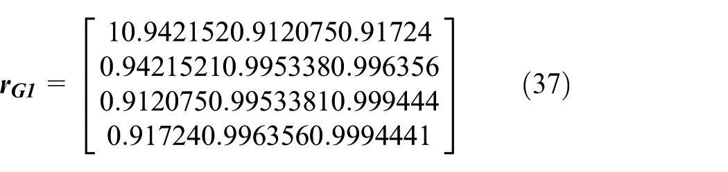
Then the wear of the number j guide wheel of the number i bogie varying with the radius of curvature can be shown as follows

The wears of each guide wheel of the number i bogie varying with curvature radius of the track line are shown as follows

Correlation analysis is carried out on

Through calculation, the correlation coefficient matrix of the guide wheel wear of non-bolster bogies is obtained as follows
The correlation coefficient matrix of the guide wheel wear of the bolster type bogies is shown as follows

In the same way, the correlation coefficient matrix of the driving wheel wear of the non-bolster type bogies is shown as follows

The correlation coefficient matrix of the driving wheel wear of the bolster type bogies is shown as follows

Known from the above analysis, for the both types of monorail, the variation of wheel wear of the inner bogies is roughly the same. The variation of wheel wear of the bogies in the two ends of the monorail is a little different from that of the inner bogies.
However, the value of each element of the coefficient matrix is higher than 0.8, which means variation of the wheel wear of bogies is almost similar.
Comparison of wheel wear of different bogies
As discussed before, the variation of the wheel wear of each bogie with the rail curvature radius is almost similar. The variation of the wheel wear in the same position of different bogies can be expressed as the variation of the total wheel wear of each bogie.
By adding the wear indexes of driving wheels in each bogie up, the total wear indexes of driving wheels in each bogie can be obtained, as shown in Figure 10. It is known from the figure, regardless of the monorail type, the driving wheels of the inner bogies wear more than that for the two ends. The wear indexes decrease with the increase of the radius of rail’s curvature.

Total wear indexes of every bogie’s driving wheels: (a) bolster type and (b) non-bolster type.
Similarly, the total wear indexes of guide wheels in each bogie can be obtained, as shown in Figure 11. It can be learned from the figure that regardless of the monorail type, the guide wheels of the inner bogies also wear more than that for the two ends. The wear indexes also decrease with the increase of the radius of rail’s curvature.

Total wear indexes of every bogie’s guide wheels: (a) bolster type and (b) non-bolster type.
Conclusion
The aim of this article is to compare the wheel wear of two kinds of articulated monorail. FIALA model is set up to simulate the wheel force. Through the theoretical analysis, the wear index of railway wheels is also proved to be effective to evaluate the wheel wear of both railway vehicles, automobiles, and the vehicles which both have the properties of the two types, namely monorail. Meanwhile, it is also proved that there is no relationship between the wheel wear and radial force, which means some methods which have been used to evaluate the wear of the monorail guide wheel are wrong. Through the co-simulation of the MATLAB and UM software, the wheel wears of the two types of articulated monorail are calculated. Known from the correlation analysis, for the both types of monorail, the variation trend of the wheel wear of the inner bogies with the track curvature radius is roughly the same. But the variation trend of the wheel wears in the two end bogies is a little different from that of the inner bogies.
The result shows that the wheels of the bolster type monorail wear more than that of the non-bolster type. Regardless of type of monorail, the wheels in the inner bogies wear more than that of two ends.
This research could benefit the manufacture of the articulated monorail. In order to further analyze the properties of it, there are still a lot of works to do. 43
Footnotes
Handling Editor: James Baldwin
Declaration of conflicting interests
The author(s) declared no potential conflicts of interest with respect to the research, authorship, and/or publication of this article.
Funding
The author(s) disclosed receipt of the following financial support for the research, authorship, and/or publication of this article: This project is supported by National Natural Science Foundation of China (grant no. 11790282) and National Key R&D Program of China (grant no. 2017YFB1201304-13).