
Abstract
Strong stiffness provided by locking-plate system has resulted in nonunion and delayed union for long bone fracture. Longer bone plate can lengthen the working length to reduce the structural stiffness of the fixation device but will enlarge skin incision. Using the semi-rigid locking screw may be helpful but the efficacy was unclear. In simulated fracture model, four rigid locking screws were continually inserted beneath the fracture gap. The other four rigid/semi-rigid locking screws were equally distributed or concentrated at screw holes superior to the fracture gap. Axial compressive load was exerted to compare the biomechanical performance under various screw configurations and plate working length. Results revealed that using the semi-rigid locking screws, the structural stiffness of the fixation structure were lowered by 29.5%–45.1% comparing to the model with the same screw configuration using rigid locking screws. Semi-rigid screw models with shorter working length represented comparable flexibility of the fixation structure to the rigid locking screw model with longer working length. Compared to rigid locking screw, semi-rigid locking screw may provide similar flexibility with shorter bone plate, which may be beneficial to reduce the required plate length so that the skin incision may be minimized for fracture reduction.
Introduction
With great capability in maintaining structural stability in treatment of bony fractures, the locking-plate system has been widely agreed in orthopedic trauma care in the recent decades.1–3 Specifically, the locking mechanism between bone screws and plate forms a strong structure without being tightly compressed to the fractured segments (required by conventional compression plate fixation), which is beneficial to patients suffered from osteoporosis.4,5 The secondary bone healing, depending on callus formation, 3 requires a greater theoretical interfragmentary strain interval between 2%–10% compared to primary healing (less than 2%). 6 However, locking plate with excessive structure stiffness would be problematic to ideal bone healing due to weakened mechanical stimulation at fracture site. Clinical problem such as nonunion, delayed union, required secondary procedures, implant failures, and loss of alignments were reported.7–9
For reducing the over-enhanced structural stiffness by locking-plate system, surgeons may sometimes choose a longer bone plate with screws locked toward both ends of it (leave the central part of bone plate empty without screw fixation), to gain a greater “working length” of bone plate. But obviously, a longer plate needs larger incision to the skin either for implantation (i.e. open reduction) or inevitable removal. In addition, an uneven formation of callus at near- and far-cortex regions has been observed in clinical cases. 10 Technique of semi-rigid locking screw for far-cortex dynamic fixation has then been introduced and was demonstrated that reduced structural stiffness and balanced intergramentary movement (near-parallel motion) shall improve the quality of bone union in several biomechanical and clinical studies.10–12
Currently, using a longer bone plate or the semi-rigid locking screw technique is commonly seen in clinical practice. In another computational biomechanical study, Heyland et al. 13 considered that the working length of bone plate influenced greater than the type of screw (locking or semi-rigid locking screw) on the structural stiffness. Different configurations of screw fixations for tuning the working lengths of bone plates (with identical length) in fixation models have been compared. On the contrary, the in vitro biomechanical study by Chao et al. 14 showed that plate working length has no effect on stiffness, gap motion, and fatigue resistance. The goal of semi-rigid locking screw for dynamic fixation is to enhance fracture healing via the theory of secondary bone healing. However, considering the minimum requirement of plate working length, it is unknown if the plate length can be reduced using the semi-rigid locking screw in a fixation construct. Therefore, the purpose of the current study was to determine if the required plate length will possibly be altered via using semi-rigid locking screws compared to rigid locking screws. Conceptual finite element study has been conducted for numerical evaluation, including hardware safety.
Materials and methods
Solid model preparation
Cylindrical model for simulating a diaphyseal midshaft fracture was constructed, with a hollow cylinder for cortex layer (30 mm outer diameter, including 4.0 mm cortex layer; Young’s modulus: 15,100 MPa; Poisson’s ratio: 0.3) and filled with cancellous bone structure (Young’s modulus: 100 MPa; Poisson’s ratio: 0.3). The full length of the cylinder was 240 mm including a 10-mm fracture gap. A 12-hole and a 9-hole bone plate was constructed, respectively, with length of 220 and 172 mm (screw hole span: 16 mm), width of 20 mm, and thickness of 5.0 mm (Figure 1(a)). The locking screw (locking screw, A Plus Biotechnology, Ltd, Taiwan) and semi-rigid locking screw (Dynamic Double Thread Locking screw, DDTL screw, A Plus Biotechnology, Ltd, Taiwan) in length of 34 mm were reconstructed with three-dimensional scanning reverse engineering and removed screw threads as shown in Figure 2. Material properties of all metallic components including bone plates and screws were titanium alloy (Young’s modulus: 110 GPa, Poisson’s ratio: 0.3).
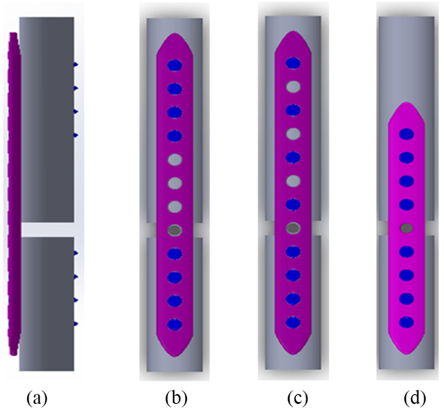
Side view and screw configurations of simulated diaphyseal fracture model fixed with locking-plate system: (a) side view, (b) L12E0, (c) L12E1, and (d) L9E0.

Reconstructed screw models by reverse engineering and simplified model for finite element analyses: (a) rigid locking screw (locking screw, A Plus Biotechnology, Ltd., Taiwan), and (b) semi-rigid locking screw (Dynamic Double Thread Locking screw, DDTL screw, A Plus Biotechnology, Ltd., Taiwan).
Screw configurations
The 10-mm fracture gap was located at the fifth screw hole counting form the bottom screw hole of the bone-plate model. A total of six fixation models were considered in this study. All of the four screw holes beneath the fracture gap were inserted with rigid locking screws in all models. Screw configurations that are superior to the fracture gap were as follows:
L12E0 model: using the 12-hole bone plate, and 4 screws were inserted at the first, second, third, and fourth screw holes counting from the top screw hole. The E0 meant no empty screw hole represented between the screws superior to the fracture gap (Figure 1(b));
L12E1 model: using the 12-hole bone plate, and 4 screws were inserted at the first, third, fifth, and seventh screw holes counting from the top screw hole. The E1 meant there is one empty screw hole between the screws superior to the fracture gap (Figure 1(c));
L9E0 model: using the 9-hole bone plate, and 4 screws were inserted at the first, second, third, and fourth screw holes counting from the top screw hole (Figure 1(d)).
Using different screws, the models were further defined as L12E0-R, L12E1-R, L9E0-R (with rigid locking screw insertions above the fracture gap), L12E0-SR, L12E1-SR, and L9E0-SR (with semi-rigid locking screw insertions above the fracture gap).
Finite-element modeling
All six fixation models were meshed with tetrahedral elements. Referring to the convergence test, numbers of elements were respectively assigned by 135,453 in L12E0-R model, 136,918 in L12E1-R model, 133,128 in L9E0-R model, 146,569 in L12E0-SR model, 143,443 in L12E1-SR model, and 141,853 in L9E0-SR model.
Bone-screw arrangements
For all rigid locking screw models (L12E0-R, L12E1-R, and L9E0-R), the screws were inserted into the cylindrical model without gap existing (Figure 3(a)). Contact between locking screws and surrogate bony structures were assigned by fully bonded to simulate well-fixed constructs. For the semi-rigid locking screw models (L12E0-SR, L12E1-SR, and L9E0-SR), the bone-screw tunnel was created referring to the nominated outer diameter of DDTL screw (5.0 mm) until the region of far-cortex locking location (Figure 3(b)). Clearance between the screw and bone-screw tunnel can be observed at the near-cortex end and the transition region of the semi-rigid locking screw. Coefficients of friction between the screw and bone-screw tunnel were assigned as 0 (frictionless) at near-cortex region and 0.5 at transition zone. Contact at far-cortex region was assign as fully bonded.

Pattern of bone-screw connection: (a) rigid locking screw with no clearance between screw body and tunnel and (b) semi-rigid locking screw with an observable clearance between the screw body and tunnel.
Boundary and loading conditions/evaluating parameters
The contact interface between bone plate and surrogate bony construct was set as frictionless, while the coefficient of friction for surfaces at the simulated fracture gap was assign as 0.5 in avoidance of possible model penetration after engagement of solid models. Gap between bone plate and surrogate bony surface was left by 1 mm. 12 All screw heads were bonded with the bone plate. A 400 N axial compression was applied on the top surface of the surrogate bony construct. This eccentric load with respect to the bone plate would generate a bending moment during simulation (Figure 4), while the model was fully fixed at the bottom surface of the surrogate bony construct. Simulated results including the axial structural stiffness and the von Mises stresses on the screws and bone plates were evaluated.

Schematic description of the resultant bending moment caused by eccentric load with respect to the bone plate.
Results
Axial stiffness
Greatest axial stiffness was observed in L12E1-R and L9E0-R models with near identical magnitudes (1428.6 N/mm). Similar performances were found for L12E0-R (727.3 N/mm), L12E1-SR (784.3 N/mm), and L9E0-SR (784.3 N/mm) models. Lowest axial stiffness was represented by L12E0-SR model (512.8 N/mm). It was noted that models with identical working length would result in similar axial stiffness using the same type of screw (such as L12E1-R vs L9E0-R, and L12E1-SR vs L9E0-SR). Visualized comparison of axial stiffness of the structure is shown in Figure 5.

Visualized comparison of axial stiffness with different screw types and configurations.
Plate stresses
For all simulated models, high stresses were all concentrated at the empty screw hole(s) within the working length region of the bone plate. Differences among all models were not obvious (197.1–201.4 MPa). Distributions of the stresses on bone plates are shown in Figure 6.

Stress distributions of the bone plates.
Screw stresses
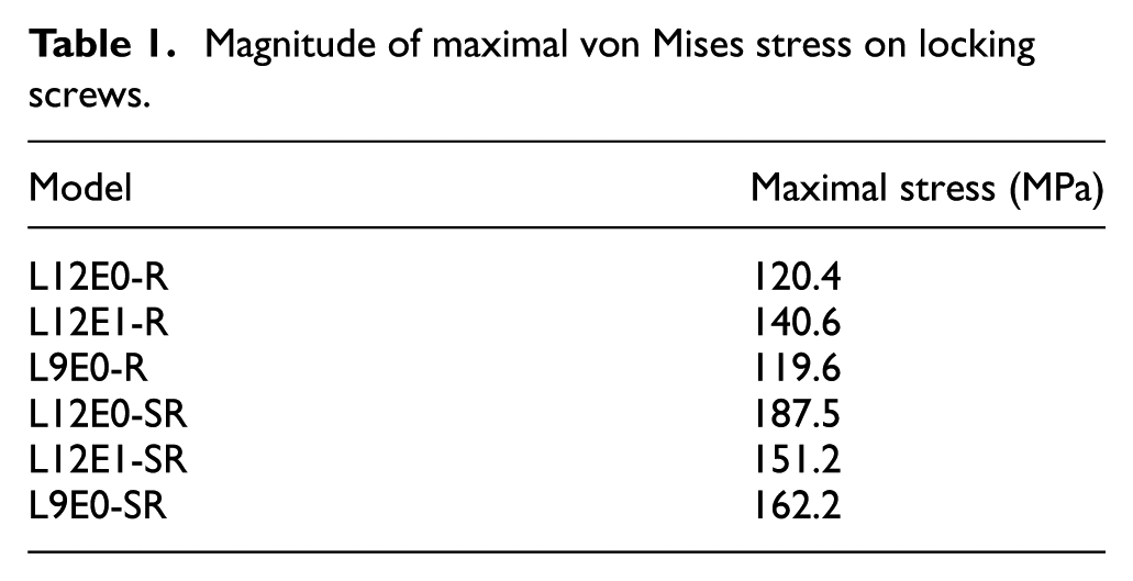
Greater magnitude of stress was generally found in models with semi-rigid locking screws. Greater magnitude of screw stress was found in L12E0-SR model on the semi-rigid screw (187.5 MPa), followed by that in L9E0-SR model (162.2 MPa) and L12E1-SR model (151.2 MPa). As for models using all rigid locking screws, highest stress was found in L12E1-R model (140.6 MPa), followed by L12E0-R model (120.4 MPa) and L9E0-R model (119.6 MPa) (Table 1). Figure 7 shows the distributions of screw stresses under various configurations of rigid or semi-rigid locking screws. Typical stress distribution on the screws in close-up view was represented. Stress on the rigid locking was found concentrated at the junction of screw head and screw body, while the stress was distributed on the screw body for the semi-rigid locking screw with a comparatively greater stress value.
Magnitude of maximal von Mises stress on locking screws.

Stress distributions of the screws.
Discussion
The finite-element analysis has been conducted in this study to determine the possible influence of required plate length when different locking screws are applied. A semi-rigid locking screw, with better flexibility at the screw body itself via reduction of core diameter of it, may be helpful to enhance the secondary bone healing effect by providing sufficient interfragmental movement at the fracture site. With the flexibility of semi-rigid locking screw, the working length of bone plate can then be reduced, which is beneficial to minimize the required skin incision during plate implantation because the plate length can be shortened. Results of this study can help surgeons to find a more suitable surgical strategy for patients when secondary bone healing is necessary in his/her clinical situation.
With advantages of great structure strength, reduced compression to bone–plate interface, and the feasibility in treatment of comminuted fractures, locking plate has been widely accepted in orthopedic trauma. Trauma implants are generally recognized as a temporary device for structural stability and will be removed after sufficient bony healing determined by surgeons. Due to different considerations in bone-healing modes, the reduced fixation stiffness is preferable in locking-plate system because better flexibility of the fixation device may provide greater interfragmental movement, which can promote better mechanical stimulation at the fracture site to achieve an ideal secondary bone healing. Previously, surgeons may choose a longer locking plate to lengthen the working length and gain the desired stiffness reduction, because more units in length may participate in the structural deflection under physiological load, caused a greater intergragmental movement or enhanced interfragmental mechanical stimulation. Although some minimally invasive techniques have been introduced that lesser and smaller incisions are required during bone-plate implantation, inevitable large incision of skin for patients to remove the bone plate is essential, since there is no mature technique for minimally invasive removal surgery for locking plates. Therefore, reducing the required length of locking plate shall be less harmful for patients who need to remove the locking plates after bone healing. This study was initiated from the concepts that possible length reduction of bone plate adequate structural stiffness shall be realized with the utility of semi-rigid screws.
Compared to conventional compression plating technique, the fixation rigidity of locking-plate system has been greatly enhanced with its interlocking (between bone plate and locking screws) mechanism that no strong compression or friction is required at bone–plate interface. This remarkable characteristic of locking-plate system has greatly promoted itself to the treatment of difficult trauma cases such as the comminuted fractures. However, in contrast to the conventional compression plate, an adequate interfragmental movement is required for achieving better bone healing. Previous studies have demonstrated that strong structural stiffness provided by locking-plate system has become an obstacle to ideal clinical outcome.7–9 In preservation of the integrity of bone plate in security issue, reducing the mechanical stiffness of locking screw has been concerned for improving interfragmental motion. Better clinical outcome and biomechanical behavior have been demonstrated in previous literatures10–12 but seldom has the required length of bone plate been mentioned, since it is highly influential to the size of skin incision either for implantation or removal. In this study, three different configurations (concentrated at the end, dispersion, and concentrated close to the fracture site) and two types of locking screws (rigid or semi-rigid) were evaluated. Low structural stiffness can be achieved by fixing the screws at both ends that leave great working length for the bone plate. The L12E0-SR model represented an even lower stiffness than the L12E0-R model and indicated that flexibility of the semi-rigid screws worked. Using the same type of screw, similar axial stiffness was represented under identical working length (i.e. L12E1-R vs L9E0-R, L12E1-SR vs L9R0-SR). This phenomenon echoes the statement by Heyland et al. 13 that the working length of bone plate dominates the biomechanical behaviors in stiffness. It is pleased to find out that a shorter bone plate can also be considerable if semi-rigid locking screws can be adequately applied (L9R0-SR), which represented a similar result in axial stiffness compared to the usage of longer bone plate with rigid locking screws fixed at the both ends (L12E0-R).
Stress on orthopedic implants has been generally utilized for determining implant safety under the simulated loads. Changes in usage or configurations of implants shall alter the biomechanical safety, which should be concerned besides of the functional performances. Working lengths of the bone plates have been adjusted in this study, but only the stress distribution was changed rather than the magnitude of stress concentrated on the bone plate. The reason is that loading condition and the full length of the surrogate structure were identical, thus the performance in the resultant bending moment (due to eccentric load) was similar. With the similar load exerted on the bone plates, it can be expected that stress will concentrate at the weak point of the structure itself (i.e. around the empty screw holes) with a similar magnitude. As for the stresses on the screws, it can be discovered that larger stresses were concentrated at the screws adjacent to the fracture site for the simulated models with rigid locking screws only, no matter the configurations of screws were continuous or dispersed. It should also be noted that high stress was presented at the region exposed from the bone. When the screws above the fracture site were replaced with semi-rigid screws, stresses on the semi-rigid screws were distributed on the whole screw body, indicated that the whole screw body has participated in the structural deformation, which contributed to the greater axial displacement compared to the rigid locking screws. However, it should also be noted that the stress value on the semi-rigid locking screws were greater than those appeared on the rigid locking screws. Greater risk of semi-rigid locking screw failure over conventional rigid locking screw should be concerned although that failure of surrogate bony structure may take place before the implants were failed, which has been demonstrated in previous biomechanical study by Bottlang et al. 11
Some limitations of the study are listed as follows:
Simplification of simulations including material properties (linear elastic/homogeneous/isotropic) and the thread feature would be influential to the results. Quantified information provided in this study may provide some new idea that how plate length/size of skin incision can be reduced in biomechanical perspective. Further test can be conducted for a more detail validation.
Differences in length, thickness, span of screw holes, and geometrical features shall be influential to the performance of bone plate. Bone-plate model with simple outline has been considered in this study to give a more objective comparison for different screw designs. Clinical performance shall be affected by the practical bone plate applied. In addition, this study only focused on the behavior under 400 N axial load, performances under different loading patterns (torsion, bending, or complex) or even greater loads exertion have not been compared. Further study should be focused on various loading pattern for complete information for the hardware usage.
Stress values represented in this study are only for determining the comparative mechanical behavior of the hardware, instead of demonstrating the practical risk of hardware usage. Operational definition of structural stiffness and the practical risk of fixation device should be further validated by mechanical tests.
Individual differences in bony structure like bone quality or different style of fracture has not been compared. Representativeness of current results should be further examined.
Conclusion
With the application of semi-rigid locking screw, the length of bone plate chosen for preserving adequate structural stiffness can be shortened. According to the biomechanical evaluation of current study, the elastic performance semi-rigid locking screw can be contributive to the reduction of required working length of bone plate and indicated that smaller incision of skin and soft tissue can be realized to minimize the damage during implantation and removal of locking plates. However, safety issue that failure of semi-rigid locking screws should be carefully concerned in further clinical and biomechanical studies.
Footnotes
Handling Editor: Jia-Jang Wu
Declaration of conflicting interests
The author(s) declared no potential conflicts of interest with respect to the research, authorship, and/or publication of this article.
Funding
The author(s) received no financial support for the research, authorship, and/or publication of this article.