
Abstract
The article deals with investigations of a prototype single and double multi-leaf spring composed of a four-leaf main spring and a double-leaf supporting spring subjected to the cyclic loads. A methodology of a measurement conducted during experimental tests and a set of research instruments used in the stand research allow evaluation of the effects of friction and the accompanying heat stress of the leaf spring in the quasi real operating conditions. The role of clearances and friction in operation of this type of construction as well as analytical, numerical, and bench testing methods used in the research on the effect of energy dissipation due to friction on operation of the leaf spring are discussed. Dynamic elastic characteristics with hysteresis loops and identification of leaf cooperation areas are presented for the single and double multi-leaf springs tested under different conditions.
Keywords
Introduction
There are numerous kinds of friction forces (e.g. internal friction, friction of construction, or friction of mobile connections) 1 in a real dependent suspension of a car equipped with a multi-leaf spring. At the designing stage, a designer chooses suitable values of variables such as elasticity and viscous damping, which are the basic characteristics of vertical movements of the suspension. At the same time, the designer consciously ignores other types of friction with characteristics and mechanical energy dissipating during movement of the suspension, which is difficult to determine. Creating a prototype, which is going to be tested in the experiments,2–6 makes it possible to determine the real values of suspension characteristics which provide the basis for determining the amount of dissipative energy. This kind of energy is produced by numerous friction forces, including, for example, friction between the surfaces of the leaves, friction at the connections of the leaf springs with the brackets at the joints, and the forces operating during deflection of the suspension. Knowledge on this kind of energy is necessary to develop models of suspensions and for simulations of their operation conducted in order to investigate the dynamic phenomena occurring between the part that is elastic and the rest of the car.5–7 Due to huge simplifications of discrete models, which do not include modeling of dry friction,6,8–10 the result of damping calculations does not fully represent the effects of energy dissipation. Moreover, the phenomenon of accidental blocking of elastic elements of the suspension may occur during the movement on the roads with low height roughness of the microprofile of the road surface. 10 In such situations, the dynamic model of suspension should differ significantly for both the suspended and not suspended parts of the vibrating vehicle. The vibrations are transferred by the stiffness of the tires.3,10,11 The omission of the dissipative energy in computational models has been a basic manner of designing a suspension, for example, to determine its elastic characteristics.1,6,10 However, there still remains a problem of making the models of suspension with vibrations taken into consideration when the dry friction1,6,10,12,13 occurs in some subassemblies of the car suspension. If dry friction is taken into account, it is necessary to deal with highly non-linear vibrations of the car suspension and its systems; 12 therefore, the analysis of the vibrations of the suspension becomes more complicated.
This study provides an overview of the research on a prototype dual leaf spring consisting of a four-leaf main spring and a two-leaf auxiliary spring.2,4,8,9 The cyclic load determined based on the usual operating conditions6,10 is used. The attention was turned to the role of friction in operation of this type of construction as well as to numerical and bench testing methods used in research on the effect of friction on operation of the leaf spring. The methodology of conducting experimental tests and the analytical method used in the research enable evaluation of clearances between spring leaves, the effects of friction, dissipating energy, and accompanying heat stress of the dual leaf spring occurring during cyclic loading with predetermined parameters.
The thermographic measurement results with suitable parameters of cyclic loading typical for operating conditions of such a construction are used to determine the heat transfer and stress that occurred on the leaf spring, during the experimental research, and an influence of friction between the spring leaves on distribution of temperature in the longitudinal plane of the leaf spring and in particular leaves. Maps of distribution and temperature charts for the measuring points located at particular leaves of the dual leaf spring are presented in the article.
The potential, dissipative energy, and dissipation coefficients determined in a single and double multi-leaf springs under different conditions of cooperation were compared based on the results of experimental and numerical studies. The comparative analysis was performed using three variants of cooperation: under conditions of dry friction, corroded surface of the spring leaves, and with the graphite grease between the spring leaves. The friction force diagrams and contact force distributions determined between single and double-leaf springs at maximum load conditions by finite element (FE) analysis were also compared in this article.
Overview of numerical investigation on friction in multi-leaf springs
In the previous studies of the authors from the Military University of Technology,2,4,7–9,12 the results of experimental and numerical research on multi-leaf dual springs are discussed. Previous studies4,7–9,12,13 include the descriptions of numerical models and the results of computer analyses of operation of leaf springs with bilinear characteristic resulting from the clearance between the leaves of main and auxiliary leaf springs, including the analysis of the friction.12,13 In the study by Borkowski et al., 12 non-linear numerical analysis is considered for a model of a prototype dual leaf spring consisting of a four-leaf main spring and a two-leaf auxiliary spring. The effect of friction forces on the stiffness characteristics over time is included in the studies. In the numerical analysis, finite element method (FEM) model was employed, where both the clearance and the friction were represented with additional one-dimensional (1D)-type elastic elements. The clearance L between the nodes WA and WB (Figure 1(a)) of this model of a leave spring was defined as a function of force P and distance δ of the nodes and is presented in Figure 1(b) as a broken line. While defining the elastic elements, the T = µP = f(ν) relationship was also specified and presented as a broken line. In the numerical model, the contact with the clearance and friction was modeled with two springs. One of them, defined on the direction perpendicular to the surface of the contact of leaves with P–δ feature, represented the clearance, and the other, tangential to the surface of the leaves, defined by T–v curve, represented the characteristic of friction. A numerical model including the friction occurring only when the parts move relative to each other along the axes tangential to the axes of the leaves of junctions located on the central axis of the leaves was employed.

Numerical models of: (a) two-node elastic element with clearance L and (b) characteristic determining the spring stiffness. 12
The other problems considered in the study by Wieczorek and Nowak 13 are numerical modeling of friction and assessment of the phenomenon effect on the variability of stiffness characteristic of a multi-leaf spring. In order to fully represent the real operating conditions of the leaf spring, a 1D model was developed (as in the case of the study by Borkowski et al. 12 ). In this model, new rod-like elements with the axes normal to the axes of the leaves and stiffness significantly higher than the stiffness of the elements of the leaves were introduced. The elements are placed between the nodes of the central axes of the leaves and the points located on the surface of the leaves. They represent the cross sections of the rods. As a result, the operation of the friction forces is influenced not only by the movement of the central nodes but also by mutual rotation of leaves. The stiffness characteristics of the model for various values of friction coefficients were determined. On the basis of resulting characteristics, potential energy of loading and unloading of the spring was calculated. Research was conducted on the effect of changes in value of a friction coefficient on the changes in the elasticity characteristics of the leaf spring. The value of elastic resistance served as a comparison criterion (the difference between the potential energy of loading and unloading the leaf spring was compared to the energy of loading the leaf spring). The use of a model of the leaf spring including additional rod-like elements, representing the cross section of the leaves, allows for significantly more exact representation of the phenomenon of friction than in the case of models without any additional elements. Therefore, in the calculations performed with numerical methods and 1D models of a leaf spring, discrete models that take relative movement of the surface of the leaves (rather than the movement of their axes) into account while calculating dissipation of energy should be used. An important issue is also implementation of an appropriate contact algorithm. 14
Several models such as a simple three-dimensional (3D) model of individual leaves or multibody models analyzed using the FEM15–17 can be found in scientific studies. They represent a different level of complexity and accuracy of the real objects mapping and, thus, different lengths of computational time determining their applications. These models can be used at various stages of the vehicle development process.
Modeling of the phenomenon associated with multi-leaf spring operation (e.g. contact between the leaf surfaces, friction, structural damping, non-linear stiffness and damping characteristics, non-linear material, and other problems) is a complex issue and, therefore, special modeling techniques are used.
The simplest models of a single parabolic leaf spring can be used in the optimization process taking into account structural fatigue, for example, to generate a diagram of fatigue life with an acceptable accuracy and a reduced computational time. 18
The 3D multibody model of a double multi-leaf spring built in LMS Virtual. Lab motion is discussed in the study by Toso et al. 17 The solids of the spring leaves are modeled using the rigid elements joined by additional elastic beam elements. The contact is mapped using a simplified model with the balls replacing the contact interaction. They are placed between the rigid solid representing the spring leaves in the known “a priori” places where the surfaces of leaves interact. The abovementioned model is less accurate than 3D FE models, and its usage must be preceded by a laborious tuning process.
Complex models of the complete bus suspension with multi-leaf springs are presented in the study by Kong et al. 19 Vibrations of an urban bus are investigated through numerical simulations with suspension component characteristics and are validated through field measurements.
Simplified modeling techniques using beam or discrete elements, including those with non-linear characteristics, are used in the majority of the presented multi-leaf spring models. It is not possible to accurately reproduce the working conditions of leaf springs, with their use including friction on the surfaces of cooperating leaves or phenomena related to blocking the leaves at small deflections.
However, such analyses are possible using spatial models built with solid elements. Such an approach is used in this article. It should be emphasized that the 3D models of vehicle suspensions presented in the literature have a strictly specialized character. They are tailored to solve specific issues. The scope of their use is limited as well. They are not suitable for mapping and investigating all phenomena regarding the operation of such type of structures.
Numerical studies using advanced 3D FE models of multi-leaf springs are discussed in the article. They include a contact phenomenon and friction between the spring leaves. The influence of different friction conditions, defined by the static and kinetic coefficients of a friction, was investigated for the quantity of energy dissipated. Numerical results of multi-leaf springs were compared with the results of selected experimental tests.
Laboratory stand and selected aspects of the leaf spring experimental investigation
The subject under consideration is a prototype dual leaf spring, presented in Figure 2, consisting of a four-leaf main spring and a two-leaf auxiliary leaf, designed for heavy goods vehicles of allowable total weight not more than 3.5 tons. The leaves of the spring were made of 60S2A steel (low carbon silicon), in accordance with PN-74/H-84032 standard. This kind of a design solution considering leaf springs is widely used in a mechanical rear suspension because it results in a bilinear stiffness characteristic due to a parallel connection of two elastic elements (main and auxiliary leaf spring) with different geometric designs (Figure 2) and stiffness coefficients. Increasing the vertical load results initially in deformation of the main leaf spring, followed by deformation of auxiliary leaf springs. The clearance between the main and auxiliary leaf springs is eliminated, hence the system is actually a new kind of a spring with a stiffness coefficient equal to the sum of stiffness of the component springs.

Diagram of a typical dual leaf spring with an area and points of temperature measurement (P1–P9): 1—main leaf spring, 2—auxiliary leaf spring, and L—clearance measured between leaves of the main and auxiliary springs.
The research was developed in Military University of Technology, using an Instron 8802 strength testing machine. A dual leaf spring was cyclically loaded under laboratory conditions with forces variable in time, the same as those occurring under operating conditions. The amplitude and frequency of loading were predetermined in such a manner that they fit to the characteristics of the operating point of the suspension. The research described in the work is continuation of the analytical and experimental research on dual leaf springs, described in previous studies.2–4,7–9,12,20
During the experiment, the leaf spring was placed in a special construction in the form of a structural channel, presented in Figure 3(a), seated on a lower footing of the Instron 8802 strength testing machine. Such a manner of mounting the ends of a dual leaf spring ensures that the horizontal displacements of the leaf spring will occur, while the vertical displacements of the leaf spring will be limited (Figures 2 and 3). It results from meeting the safety requirements. As a result, a real dependent car suspension equipped with a so-called free leaf spring was presented.2,4,6,10

Setting the dual leaf spring on Instron 8802 strength testing machine: (a) unloading spring: 1—main leaf spring, 2—auxiliary leaf spring, 3—point of load application, and 4—guiding structural channel and (b) loading spring at the laboratory stand and thermal camera.
The main purpose of this study is to determine the results of cyclic load, typical for operating conditions of this construction as well as heat stress that occurred during the experimental research on the leaf spring, and an influence of its friction in the spring on the distribution of temperature in the longitudinal plane of the leaf spring and in particular leaves.
Cyclic input was applied in the central part of the leaf spring (Figure 3(a)). The measurement of deflection and loading force was conducted with measuring devices integrated with the strength testing machine. In order to measure the temperature, a thermal camera was applied (Figure 3).21,22 Figure 3(b) presents the location of the thermal camera. The temperature is measured at discrete points of the dual leaf spring. The camera mapping included the left half of the leaf spring. Nine measurement points (P1–P9) were chosen, and their designation and detailed description of localization are presented in Figure 4(a).
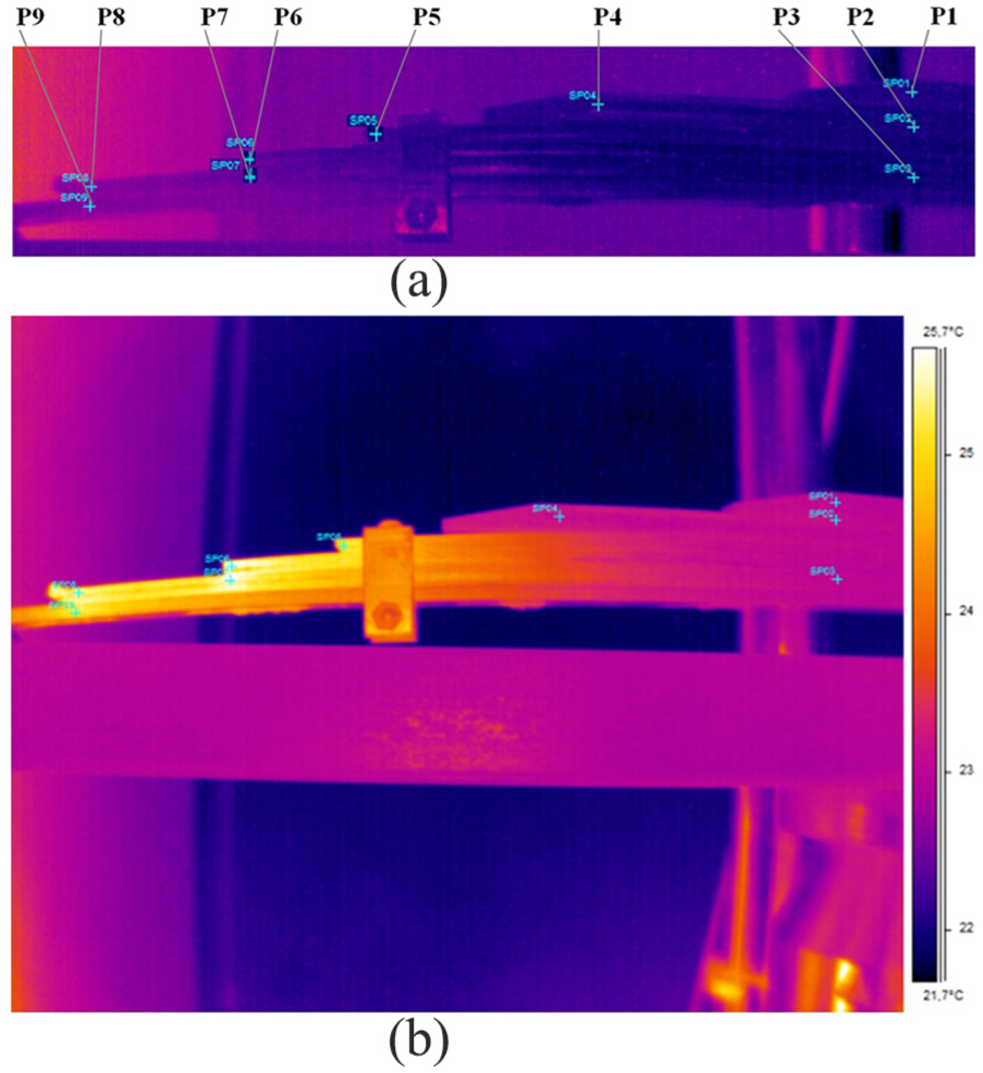
Dual leaf spring left half, without loading, with designation of the location of the temperature measurement points (P1–P9) during cyclic load in phases: (a) t = 0 min and (b) t = 340 min. 23
Laboratory stand tests using a thermal camera for the dual multi-leaf spring investigation at cyclic loading are discussed in detail in the study by Krason and Wysocki. 23
The thermal camera is mounted on a laboratory stand (Figure 3) and coupled with a computer-recorded temperature on a real-time basis. It allowed taking thermal photographs (Figure 4) with exposure of the chosen measurements points. The results from thermal research are used to determine the temperature field on the surface of the leaf spring during cyclic load in the various phases and at the chosen points (Figure 4(a) and (b)).
Loading force was measured with ±250 kN measurement cell integrated with a strength testing machine. Control of measurement adequacy of the force–load cell equals to at least ±0.25% of the records with the value of 0.25 kN and more. 24 The sensitivity of the thermal camera is ±0.1 K, which means that a picture represents differences of 0.1 K and greater. On the basis of the previous research and tabular data in the literature, 25 it was assumed that the emission performance is 0.85 (the same as for the steel with oxidized finish).
Measurements of loading force and displacement in time are recorded with 100 Hz frequency of data sampling. Duration of the experiment was 340 min. During this time, the strength testing machine performed over 37,190 loading cycles. On the basis of the research results, charts representing the relationship between the temperature and the duration of cyclic loading were prepared. Parameters of the cyclic loading test are presented in Table 1.
Parameters of the cyclic loading test of the leaf spring.

The results of bench tests of the leaf spring performed with a thermal camera in the form of pictures representing distribution of the temperature on particular leaves of the dual leaf spring are presented in Figure 4. The results of temperature measurements performed at points (P1–P9) at the starting moment (t = 0 min) and for the last phase of the cyclic load (t = 340 min) are presented in Table 2.

The greatest increase in temperature was recorded close to P6 point, which is at the end of the fourth leaf. The second relatively high increase was recorded for the area close to neighboring P7 and for the ending of the fifth leaf (P8) and the neighboring one (P9). Leaves of the auxiliary spring are the least stressed by heat. Middle parts of the leaves cooperate to some extent, however not fully, with the neighboring elements. In the middle parts of spring leaves, the recorded increase in the temperature was the smallest. Therefore, those areas of the spring leaves are the least exposed to the operation of loadings resulting from friction and, due to friction, they are also the least worn.
For measurement values of temperatures, however, not for the initial temperature of the leaf spring, the approximation functions of measurement results are calculated with MATLAB code. 26
The form of equation (1), describing temperature changes at selected measuring points (P3, P6, and P8), is determined for the individual leaf springs on the basis of the experimental results (Table 2). This equation was used to extrapolate the temperature values for t = 600 min

where Tu is the steady state temperature (°C), T0 is the initial temperature (°C), t is the time (min), and k is the time constant (accepted as 4.5 × 10⁻³) (1/min).
The charts mapping the relationship between the temperature and the duration of cyclic loading are prepared on the basis of the values of the temperatures at specific points (Table 2) (Figure 4). The curves T(t) shown in Figure 5 represent the changes in the temperature as a function of the test duration. It can be observed that more diversified conditions of operation (in terms of temperature changes) occur in the area where the endings of the leaves come into contact with the surfaces of neighboring leaves. As a result, in the further part of the analytical study, only two extreme ranges of the results represented in Figure 5 by curves T3(t), T6(t), and T8(t) were taken into consideration.

Analysis of temperature distribution in the selected points of the dual spring with the cyclic load could distinguish the following phases.
Phase I (from t = 0 to 40 min)—the initial phase is characterized by an intense increase in temperature on the friction surface of the multi-leaf spring (Table 2).
Phase II (t = 40 to 340 min)—has a lower maximum temperature increase on the friction surfaces of the dual spring.
Phase III (t > 340 min)—the phase is an estimation of temperature changes on the surfaces of the spring after a time of 600 min of continuous spring operation under cyclic loads.
Maximum temperature values at the ends of the leaves of the spring were determined on the basis of extrapolation functions T3(t), T6(t), and T8(t) in the case of making the experiment of cyclic loading/unloading of the leaf spring duration longer up to 10 h. This time span was assumed to be operationally acceptable time of uninterrupted travel of a heavy goods vehicle (Gross Vehicle Mass < 3.5t).2,4,8,9,23,27 The assessed maximum temperatures at the ends of spring leaves are 23.7°C, 26.6°C, and 26.1°C, respectively. This increase in temperature will not influence the changes connected with the treatment of leaf springs (involving heat treatment and plastic working, which results from the fact that these processes take place in significantly higher temperatures than temperatures measured in the experiment).
Methodology for determining the amount of dissipative energy in the friction process of leaf spring
Experimental and analytical approaches
A real characteristic of the suspension (the single or dual multi-leaf spring) with a hysteresis loop provides the basis for determining the value of the dissipative energy (e.g. Figures 6 and 9) for different values of the load parameters.
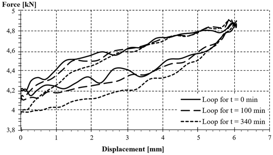
Comparison of the hysteresis loops occurring under the condition of cyclic loading dual leaf spring within the time: t = 0, 100, and 340 min.
In the case of forced vibrations, damping in the system is represented in terms of specific damping capacity Ψ, defined as a ratio of dissipative energy (Er) during one full vibration period to the maximum potential energy in this period. 1 One course (one vibration period) within the range of full deflection of the suspension is chosen for the analysis. With a discrete set of experiment and FE results for P = F(f) functions (Figures 6 and 9), the values of the following variables were calculated.
Potential energy of loading the leaf spring—E0 (based on function no. 3),
Dissipative energy (resulting from operation of dry friction forces)—Er (based on function no. 4),
Specific damping capacity Ψ (based on function no. 2)

Potential energy of loading and dissipative energy were determined by means of numerical integration of the area under the line of the force–displacement chart, P = F(f) (Figure 6). Excel software was used to prepare the charts. The following formula was used for calculation of E0

where fmax is the maximum leaf spring deflection and n is the data number for f = fmax.
Dissipative energy, Er, was represented as integration along a closed curve, in accordance with function no. 4. The second integral in formula (4) is negative

where f0 is the initial value, fk is the terminal value, and n is the total number of data.
The proposed method of determining a specific damping capacity Ψ was employed during the analysis of the experimental and numerical research results on various types of leaf springs.
Bench research on dissipative energy of dual leaf spring
This part of the work includes a description of the selected results of bench research on the leaf spring performed with a thermal camera under the conditions of cyclic changing load, representing typical operating conditions of a vehicle suspension.28,29 Three hysteresis loops in the form of a “Force–Displacement” curve and other results of the research are recorded for the tested object.
Comparison of the hysteresis loops which occurred under the condition of cyclic loading the dual leaf spring within the time: t = 0, 100, and 340 min are shown in Figure 6. The dynamical parameters of the dual spring are determined based on the methodology described in section “Experimental and analytical approach.” Load energy and dissipative energy during cyclic loading the leaf spring according to loops recorded during the experiment periods represented in Figure 6 are compared in Table 3.
Dissipative energy during cyclic loading of the leaf spring—chart of loops recorded during the experiment, t = 0–340 min.

Table 3 includes information on the share of dissipative energy during the cyclic load in the charts of the loop recorded in the maximum duration of the considered test. A diagram of the specific damping capacity changes as a function of the research time and approximations of the measurement results is presented in Figure 7. The maximal value of the specific damping capacity determined from the approximation process is equal to Ψ(600 min) = 0.072.
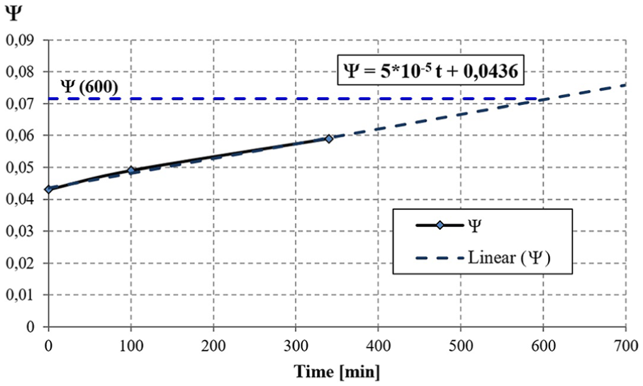
Diagram of the dissipative coefficient changes as a function of the research time and the approximations of measurement results: Ψ(600 min) = 0.072.
Numerical approach in research of friction coefficient influence on dissipation energy in multi-leaf spring
Based on the literature review, it has been found that an influence of the friction coefficient on the energy dissipation is poorly recognized for multi-leaf springs.2,5,6,12
The values of friction coefficients presented in the professional literature change in a large range. They depend in a significant way on the surface of the cooperating pair of materials, including its roughness, the hardness of the surface layer, and the type of an intermediate layer (lubricant). The values of friction coefficients depend on the method used for determining the friction forces as well.1,30
Based on the investigations of the conditions of the multi-leaf spring operation, it has been found that the conditions of cooperation between the adjacent spring leaves changed during their operation. There is usually a layer of graphite grease between the leaves in the initial stage of operation. The grease layer is successively removed during the operation of the spring and cooperation of the leaves is similar to the conditions of dry friction. The layer of oxides appears on the surfaces of the spring leaves in addition.
Therefore, the study attempts to estimate the influence of static and kinetic friction coefficients on the quantity of energy dissipated during the load and unload cycles of the spring. The analysis is performed using two simulation models (Figure 8). The first model—a single spring for a 12-ton vehicle (Figure 8(a)) consists of seven leaves with the same cross section (12 mm thick and 80 mm wide). Eight-node solid elements are used to build the FE model. The complete numerical model of a single spring consists of about 12,000 elements.

FE models of multi-leaf springs: (a) single and (b) dual.
The other model (Figure 8(b)) represents a dual spring for the rear suspension of a truck with a weight of up to 3.5 tons. The spring is also an object of experimental research presented in sections “Overview of numerical investigation on friction in multi-leaf springs” and “Laboratory stand and selected aspects of the leaf spring experimental investigation.” The analyzed spring consists of six leaves, the first four of which create the main spring, whereas the last two create auxiliary springs (according to Figure 2). All leaves have the same width (60 mm); however, they differ in thickness. Eight-node solid elements are used to build the FE model. A complete numerical model consists of about 28,000 elements.
A contact with friction forces is defined between the leaves. The coefficient of friction is calculated in the LS-Dyna 31 system on the basis of dependence (5)

where µs is the static coefficient of friction, µk is the kinetic coefficient of friction, γ is the exponent determining the change of coefficients as a function of relative velocity, and vrel is the relative velocity of the cooperating surfaces.
Numerical analyses are performed in two stages. A compression of the leaves in the middle part of them is necessary to mapping in the initial phase, due to the different radii of the spring leaves. It ensures the introduction of initial stresses and the appearance of the contact forces between the leaves (e.g. generating friction forces). The second stage of analysis is performed to load and unload the spring. The springs are supported in the middle part and loaded at the end of the longest leaf by vertical forces with variable amplitude F0 = 20 kN (for FE model in Figure 8(a)) and F0 = 8 kN (for FE model in Figure 8(b)). The forces change according to function F(t) = F0(1 – cos(ω·t)). The specified force value allows straightening of all the spring leaves. Simulation tests are performed for three variants of the friction coefficients, corresponding to the possible conditions of the interacting spring leaf surface—the clean and dry surface, the graphite greased surface, and the thin oxide coating. The static and kinetic friction coefficient values are based on the literature data 30 and are presented in Table 4.
Coefficients of static and kinetic friction. 24

The stresses in the individual leaves, deflection of the spring, values of the forces interaction on the individual leaves, potential energy (deformation obtained during load and unloading of the spring), and the dispersion in the system (including energy of the friction force) are calculated as a result of FE analysis. Figure 9 shows the dependence of the external load force on the spring displacement (elastic spring characteristics) for the assumed variations in surface conditions.
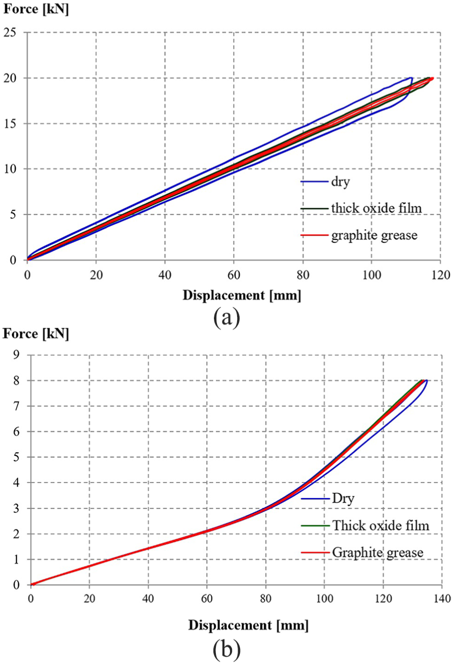
Elastic characteristics of multi-leaf springs obtained in simulation tests for different surface conditions: (a) single spring and (b) dual spring.
The graphs in Figure 9 show hysteresis loops whose surface areas are proportional to the dissipation energy. When the friction coefficients decrease, the loop fields are decreased and, hence, there is practically no difference in force values during load and unloading of the spring. The values of elastic energy, dissipation energy, and coefficient of non-elastic resistance during the loading and unloading cycles are determined based on the obtained numerical results. Numerical results are compared in Table 5.
Potential energy, dissipation energy, and specific damping capacity.

The largest quantity of energy is dissipated for clean dry surfaces of the leaves in the analyzed cases. The specific damping capacity Ψ for single spring reaches about 14% (Figure 8(a)), while for the dual spring (Figure 8(b)) about 4.5% in discussed variants. The smallest energy is lost between the grease-coated leaves of spring. The specific damping capacity for this variant is Ψ = 1.5% and 1.2%, respectively.
Additional aspect of FE analysis of single and dual springs with friction
The results obtained during numerical analyses show that the friction coefficients (Table 4) between the spring leaves influence on the quantity of dissipation energy and they depend on the construction of the analyzed spring. The number of interacting leaves in spring and the magnitudes of normal forces operating in the contact zones between leaves spring have a great influence on the energy dissipation. The vertical component of the contact forces on the surface of the leaves in FE models is presented in Figure 10.
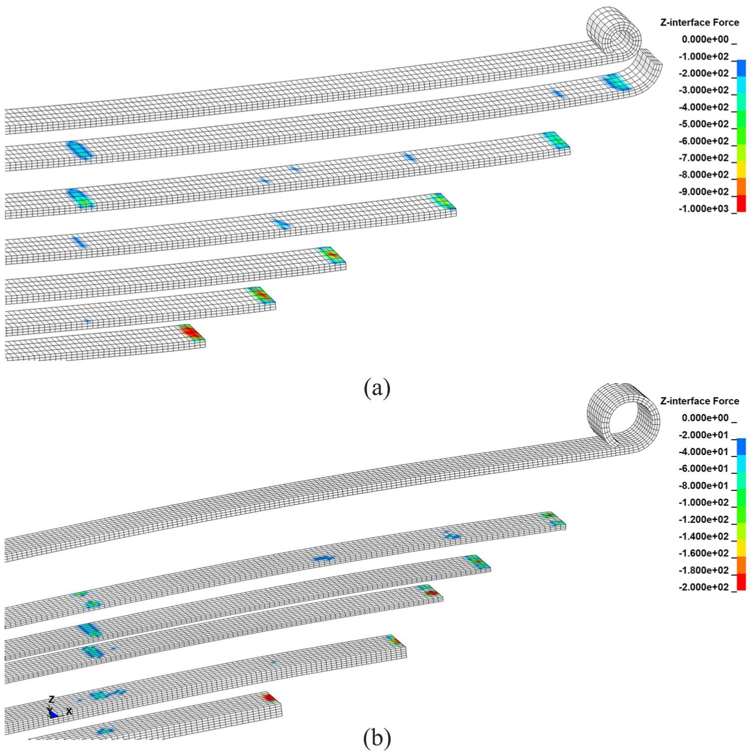
Distribution of vertical contact forces on the surface of the multi-leaf springs: (a) single (Figure 8(a)) and (b) dual(Figure 8(b)).
Experimental and numerical results clearly show that the cooperation between the adjacent leaves occurs mainly at their ends. The highest values of friction forces are also generated there. Similar force values are also observed in the middle part of the spring. They result from precompression of the leaves through the pulling bolt. Places of the greatest wear and tear of the cooperating leaves in the spring also confirm the abovementioned conclusions.
As a result of numerical tests, the interaction areas between the spring leaves are identified at the ends of spring leaves and in the cross sections of the screw mounting or the yoke connecting the spring packet. The abovementioned conclusion is confirmed by the results of the experimental studies discussed in section “Laboratory stand and selected aspects of the leaf spring experimental investigation” and the thermal imaging maps shown in detail in the study by Krason and Wysocki. 23 It is helpful to build 3D numerical models in the process of the multi-leaf springs design with a simplified mapping of the contact areas between surfaces of the spring leaves defined “a priori” in the predicted place of their frictional contact interactions.
Conclusion
Methods for the experimental tests developed under laboratory conditions and an analytical method for research of the multi-leaf dual spring are presented in this article. A friction influence on operation parameters of the spring is estimated based on the dissipative energy analysis and the measurement of a heat stress in the dual leaf spring during cyclic loading. The amplitude and frequency of loading typical for operating conditions of a car suspension are used. Thermal vision techniques are employed and thermal maps, representing the distribution of the temperatures in the longitudinal plane of the leaf spring on particular spring leaves are compiled. The following statements have been inferred from the results of the research.
Thermal vision research makes it possible to provide a detailed localization of the points of high friction supporting the results of the test performed on the phenomenon of the dissipation of energy of the leaf spring resulting from friction.
The effects of friction are the main reason of the increase in the temperature on the surface of the leaf spring. Changes in the distribution of the temperature over time are non-linear. The greatest increase in the temperature occurs in the initial phase of the tests, especially in those leaves that are exposed to contact with surfaces of adjacent leaves.
Maximum temperature values at the ends of the leaves of spring are determined on the basis of extrapolation functions, in the case of the experiment of cyclic loading/unloading the leaf spring in the period longer up to 10 h. The assessed maximum temperature at the ends of spring leaves is 26.6°C (Figure 5).
The results of numerical analyses of 3D models of multi-leaf springs (Figure 8), in which the coefficients of friction are changed on the contact surfaces of individual leaves, confirm these observations as well. The maximum contact pressure and friction forces (Figure 10) are identified in the contact areas of the end of the leaves with the upper surfaces of the adjacent leaves of the discussed FE models. This is also confirmed by the excessive wear of the end of the leaves caused by the operation of the car under various weather conditions and loads, for example, the type and condition of the road surface, mass of the carried load, speed of movement, and so on.
It is possible to assess the amount of dissipative energy, resulting from the friction in the leaf spring, using the developed methodologies.
Values of the dissipative energy are determined on the basis of hysteresis loops (Figure 6) for the load conditions given in Table 3.
Based on the experimental results (Table 3), it is found that the value of energy dissipation increases with an increasing time of exposure to cyclic loading.
The specific damping capacity Ψ (Figure 6) increases with respect to the beginning of the experiment (t = 0 min) by approximately 14% (t = 100 min) followed by 37% (t = 340 min). For the estimated time of an impact of the cyclic loading (t = 600 min, Figure 5), its value increased to 67%.
The numerical coefficients of energy dissipation indicate the influence of the spring construction (single and dual) as well as the number of leaves for energy dissipation. The specific damping capacity for the seven-leaf single spring is greater than for the dual springs in all considered cases of the surface condition of the leaves.
The results of bench tests and numerical analyses can be used to design multi-leaf springs in the 3D modeling process with a simplified representation of the contact areas between the leaves defined “a priori” in the predicted places of their frictional contact interactions. 17
A methodology for measurements and loadings used in the research, typical for the usual operating conditions, and heat stress resulting from mutual operation of dual spring leaves as well as the results of experimental research will be used to verify and refine numerical models describing the abovementioned phenomena caused by cyclic loading in the strength tests and different cases for dynamic analysis.
3D FE models of the multi-leaf springs, used in this study, accurately reflect structural solutions of the spring with the necessary details, internal constraints with clearances and frictional contact interaction between the spring leaves, the precise constitutive models of the materials used in them and load models, and variable over time, determined on the basis of actual operational loads of multi-leaf springs. 3D FE models enable performing multivariate analysis with mapping of various dynamic load conditions and realistic operating states of a multi-leaf spring interaction. However, their application is laborious and requires long-term calculations due to the geometric and physical non-linearities of the analyzed spring models.
Footnotes
Handling Editor: James Baldwin
Declaration of conflicting interests
The author(s) declared no potential conflicts of interest with respect to the research, authorship, and/or publication of this article.
Funding
The author(s) received no financial support for the research, authorship, and/or publication of this article.