
Abstract
To overcome the limitation of constant Poisson’s ratio in bond-based peridynamics, an ordinary state-based peridynamic (OSB PD) model was applied to simulate dynamic crack propagation in Kalthoff–Winkler specimen subjected to a low velocity impact. A typical linear peridynamic solid material constitutive was implemented to characterize the materials’ behavior. This article focuses on capturing the underlying mechanisms of dynamic crack propagation; thus a wave propagation analysis was conducted, and the analysis was further verified by changing configurations of the specimen in horizontal and/or vertical directions. In addition, to evaluate the influence of parameters, a detailed parametric study of impact speed, plate thickness, and notch tip radius was performed. Crack initiation and propagation results agree well with experimental observations. Through parametric analysis, it was found that the impact speed has a remarkable influence on both crack propagation speed and crack path: increase of impact speed causes increased crack propagation speed and decreased crack angle; plate thickness has influence only on crack propagation speed: thicker plate leads to lower crack propagation speed; and notch radius has almost no influence on both of them.
Keywords
Introduction
Fracture and failure analysis has always been one of the major concerns in theoretical studies and engineering applications. For mode II dynamic loading conditions with high rate, experiments have demonstrated that failure in shear form can be easily obtained if suitable fixtures are applied.1,2 The technique of loading edge cracks by edge impact (LECEI) introduced by Kalthoff provides such a fixture, in which a loosely positioned flat plate (target) with two parallel notches is impacted by a projectile. During the impact process, a compressive stress wave is triggered, and the displacement associated with this stress wave creates a pure shear mode II loading condition in a very short time period, and an effective mode II crack propagation path can then be observed.
For target plate made of steel, the failure mode transition can be observed when the strain rate (projectile impact speed) varies from low to high, the crack form failure translating to adiabatic shear band (ASB) form, because the latter has a higher capability of energy absorption. ASB analysis involves discussion on plastic constitutive material model and other related issues, which is more complicated. The main purpose of the present work is to demonstrate the capability of state-based peridynamic method in modeling dynamic brittle fracture. Thus, only crack propagation will been focused in this article.
Two pre-existing notches in the target plate can be regarded as strong discontinuities. 3 When dealing with strong discontinuities, difficulties evolved in the discontinuous displacement that cross the surfaces of discontinuity will be encountered. And the difficulties increase considerably if dynamic effects are involved in modeling. Finite element method (FEM) is a powerful tool used previously to handle this problem, including crack propagation, ASB formulation, and crack branching. These specified FEMs can be separated into two main categories, element-based enhancement method and node-enriched method, respectively. The representative of element-based enhancement method is cohesive element method, that is, the use of cohesive elements cross element edges, as introduced in literatures,4–8 and especially J Oliver 9 who considered dynamic effects in finite element with embedded discontinuities, but within the context of regularized strong discontinuities. A typical node-enriched method is the so-called extend finite element method (X-FEM), which was developed by Belytschko and Black, 10 Moës et al., 11 N Moës and T Belytschko, 12 DBP Huynh and T Belytschko, 13 Wells and Sluys, 14 and Hansbo and Hansbo. 15 Recently, X-FEM was applied by Q Meng and Wang16,17 to study the LECEI problem. For comparative study of these two methods, one can refer to Falk et al. 18
Though the two methods mentioned above have been proved to be applicable and accurate in analyzing dynamic crack propagation problems, both are non-direct FE methods, for the equations of motion of classical mechanical theory that FEM based on involve derivative terms of displacement, which do not have definition on discontinuity surfaces like cracks and voids. In addition to that, the estimation of crack initiation, growth, and propagation requires the crack position, crack growth speed, and crack direction to be defined in a priori. It seems unnatural and non-physical when the crack behavior is not known beforehand; thus, a uniform mathematical framework of mechanics should be developed in which discontinuities can be handled without any extra treatments. Lattice models 19 and atomistic models20,21 provide another approach to analyzing dynamic fracture. However, a great deal of work remains to be done in relating lattice or atomistic models for a more general continuum mechanics context. In addition, it is worth understanding dynamic fracture at scales larger than the atomistic scale.
Recently, the peridynamic (PD) theory was introduced in order to handle problems with discontinuous fields.22,23 PD is a nonlocal continuum formulation of classical mechanics, which allows for a natural treatment of crack initiation, growth, and propagation. And it can also be regarded as an upscaling form of molecular dynamics.24–26 Equations of motion of PD are in integral–differential form; thus, it is natural for PD to solve fracture problems containing discontinuities. The original PD formulation introduced by Silling 22 is called “bond-based” PD(BBPD), in which continuum body is discretized into a lattice of particles interacting through pair-wise bonds. In this formulation, the interaction of each bond is independent with other bonds, limiting the material’s Poisson’s ratio to be a constant, that is, 1/4. Though with limitation of constant Poisson’s ratio, BBPD has already been applied to many problems involving discontinuities, for example, the work of WK Hu et al 27 and YL Hu and Madenci 28 on composite materials and W Gerstle et al. 29 and W Gerstle. 30 on concrete structures. To overcome the above limitation, Silling et al 23 reformulated BBPD with the conception of state, leading to the state-based PD. And the state-based PD has two forms, which are ordinary state-based (OSB) PD and non-ordinary state-based (NOSB) PD, respectively. The relationship and difference between bond-based PD and the two above state-based PD was discussed in the work of Silling et al. 23
Damage or localized indicator in a PD model has a clear meaning. The critical stretch in PD is defined as the ratio of broken bonds and all bonds within a finite distance (PD domain). The critical stretch of each bond is related to material energy release rate. Thus, it has a definite physical meaning. Because the distribution of bonds within a domain is arbitrary and is almost in every direction, crack can initiate and propagate in an arbitrary direction where energy balance is satisfied. As to the contact algorithm between projectile and target, a simple “short-range force” model developed by Silling et al. 22 is used in our simulation; details of the contact algorithm will be presented in the “Basic Theory” section. A general elastic LPS material constitution was adopted in the analysis.
PD simulation of LECEI experiment has already been done by Silling and Bobaru 24 and E Madenci and E Oterkus 31 using BBPD model. However, limitations of bond-based PD may have a negative effect on the crack propagation results, which can be overcome by applying the state-based PD. In this article, we implemented an ordinary stated-based PD to study the crack propagation behavior of K-W specimen subjected to low velocity impact. Results from OSB PD were compared with that of experiments, and a wave propagation analysis was also conducted to explore the underlying mechanisms of crack propagation. A parametric study on impact speed, notch radius, and target plate thickness was conducted to further explore damage mechanisms under impact.
Basic theory
The notion of PD state is utilized to address the limitations on the central-force assumption in BBPD, allowing the interactions between bonds.
The equations of motion of state-based PD can be presented as
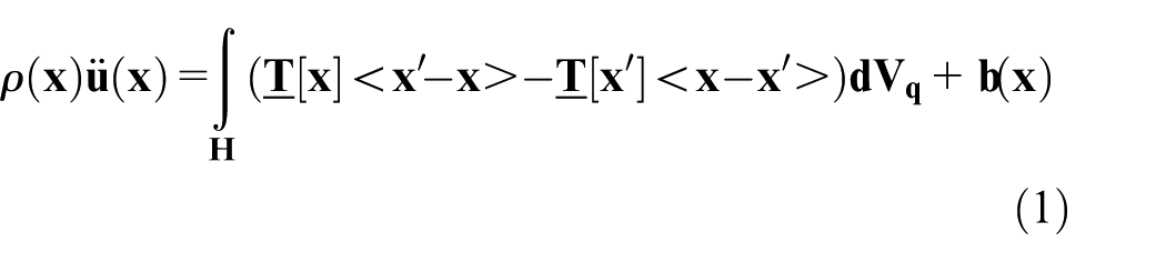
in which

The stretch of a “bond” has a similar meaning as “strain”

where

Then the damage at a material point can be defined as

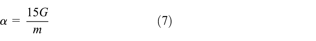
The linear peridynamic solid (LPS) model was used in simulation. Herein, only the constitutive relation is given; readers can refer to Silling et al. 23 for more details. The elastic properties of LPS model can be determined by Bulk and Shear moduli; it is a nonlocal analog to a classical linear elastic isotropic material. The force scalar state of LPS model is expressed as

with K the Bulk modulus, m the weighted volume,


with the extension scalar state

The domain volume associated with

The spatial discretization can be taken as follows
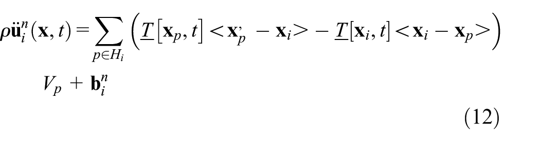
where n is the time step number and the subscripts denote the material point number.
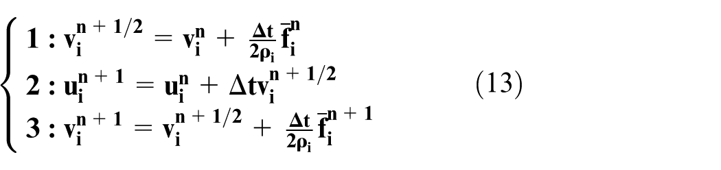
A velocity–Verlet scheme, with both the position and velocity of the material point stored explicitly, was used to compute equation (12). Its scheme is generally expressed in three steps
where

where

with

Numerical simulations
As already demonstrated,23–26 the integral–differential form of motion equations in PD is very suitable for the analysis of dynamic crack initiation and propagation. Crack initiates and propagates arbitrarily along the direction where bonds within a finite distance break at the critical stretch. In this work, an OSB PD model was applied to study dynamic shear failure and crack propagation of LECEI problem.
Schematic of the setup of Kalthoff’s experiment is presented in Figure 1; a rectangular plate with two parallel notches is impacted by a cylinder projectile with a constant speed
Schemetic setup of Kalthoff’s experiment.
Damage patterns obtained by OSB PD simulation are shown in Figure 2, in which the crack initiation, growth, and propagation with regard to time are presented. Crack initiates at about 25 μs, which is slower than the time in Q Meng and Wang’s 16 work, even though our impact speed is higher, which suggests that the material in PD has a softer “mass matrix.” In addition to the discrepancy in crack initiation time, the total time of the effective Mode II crack propagation is also quite different. In our simulation, it is about 30 μs, that is, from the states shown in Figure 2(a)–(g), where the end signal is the slight damage at the bottom presented in Figure 2(g). In Q Meng and Wang’s 16 work, the total time is more than 60 μs, and they did not give any indicator that points out when should the effective crack propagation finish. Generally, the path angle with regard to the ligament is about 60° at the crack initiation and about 70° (calculated by the least square method) in the effective path stage (defined later), which agrees well with Kalthoff’s experimental results. After the effective Mode II crack propagation process, a deviation in the crack path was observed, which almost parallels the bottom line, as described in Figure 2(h)–(j). A slight asymmetry can be seen from the result, and the search algorithm and cutoff error could be the main reasons shown by Hu et al. 27

Crack initiation, growth, and propagation: (a) 25 μs; (b) 30 μs; (c) 35 μs; (d) 40 μs; (e) 45 μs; (f) 50 μs; (g) 55 μs; (h) 60 μs; (i) 65 μs; (j) 70 μs.
In this work, the whole crack propagation is separated into three stages by its own characteristics, which are the origin stage, the effective crack path stage, and the late time effect stage, respectively, as shown in Figure 3, in comparison with experimental result obtained by Kalthoff. 2 The crack path angle in the origin stage is usually a little smaller than that in effective path stage, which is about 60° in the first series, and the time period of the origin stage is relatively short. Within the effective path stage, the Mode II crack propagation starts and ends, with the crack path angle about 70°. Within the late time effect stage, the crack propagation path after the Mode II crack ends; in this stage the pure Mode II loading condition disappeared.

Comparison between Experimental and PD result: (a) experimental result; (b) PD result.
To illustrate how these three stages are defined, a wave propagation analysis is conducted, which is consistent with the essence of the LECEI experiment, that is, the displacement associated with stress wave field generates a Mode II loading conditions at the crack tips. The velocity form wave propagation during the evolution of the crack tip can be extracted from our model. And this wave propagation will be used to analyze the characteristics of the crack propagation and dynamic shear failure. As presented in Figure 4, at about 10 μs, the wave just reaches the notch tip; the notion “wave front” can be defined here to describe the wave shown in Figure 4(a). From this time, the wave starts to form a mode II shear loading; after the wave front, that is, from Figure 4(b)–(e), the wave starts to spread in a pattern of longitudinal wave, which is called the “compressive wave” in Kalthoff’s 2 work.
Wave propagation during the evolution of the crack tip: (a) 10 μs; (b) 13 μs; (c) 16.5 μs; (d) 19 μs; (e) 21 μs; (f) 25 μs; (g) 30 μs; (h) 35 μs; (i) 40 μs; (j) 45 μs; (k) 50 μs; (l) 55 μs; (m) 60 μs; (n) 65 μs; (o) 70 μs.
Herein, an explanation will be given on how the reflected waves from edge boundaries would affect the crack propagation. Because of the velocity difference induced by the original compressive wave around the crack tip, the crack propagates, then the reflected waves even this velocity difference, which weakens the effective crack propagation process. By this explanation, the PD results can be analyzed quantitatively rather than qualitatively. At about 21 μs, the wave reaches the bottom boundary and is reflected by the boundary at about 25 μs, as shown in Figure 4(f). A significant velocity difference of about 15 m/s around the notch tip can be observed at this time, the velocity on the right side is higher. This velocity difference drives the crack initiation. When the crack tip starts to propagate, the crack tip generated at each time point serves as a point source, and the monopole source type wave shape can be clearly observed in Figure 4(g)–(l). When the time arrives at about 60 μs, that is, the time when the effective Mode II crack propagation ends, this monopole source type wave shape becomes vague, and the wave shape after 60 μs, as shown in Figure 4(n) and (o), just become messed, which suggests that the compressive wave completely disappears.
Waves reflected by the edge boundary play an important role in the crack propagation; they weaken the crack propagation process. To realize the role of reflected wave on crack propagation, the geometry of the plate is modified in both horizontal and vertical directions as shown in Figure 5. Keeping notch tip radius, notch length, impact velocity, and plate thickness fixed, the length extends by 100 mm in horizontal direction as shown in Figure 5(b), extends by 100 mm as shown in Figure 5(c), and reduces by 50 mm in vertical direction as shown in Figure 5(d). The crack propagation path and wave field are estimated for each specimen.

Geometrical extension/reduction in horizontal and vertical direction: (a) original setup; (b) horizontal extended; (c) vertical extended; (d) vertical reduced.
First, the crack propagation path and the corresponding (velocity) wave field or kinetic energy for horizontal extended setup are investigated, and some interesting results can be seen from Figure 6. The crack propagation process changes significantly compared with that of original geometry. The crack still initiates at about 25 μs, and propagates at about 37 μs, with crack angle about 60°. However, a crack arrest phenomenon is observed after 37 μs, lasting to 140 μs when a crack branch was observed. This crack branch is symmetric with the first one with regard to the notch. A second crack branch is observed at about 145 μs, shortly after the first one. And the final crack path figure is described in Figure 6(e), it can be observed that the shear mode fracture process disappears in this case. The wave field is depicted in Figure 6(f)–(j), from which it is shown that, at about 25 μs, the compressive wave does not reach the bottom boundary though crack initiated by velocity difference around the notch tip; at about 37 μs, the waves that reflected back form the vertical boundaries even the wave velocity around the notch tip, then the magnitude of the monopolar source wave starts to decrease, which leads to a crack arrest phenomenon. The vertical boundary reflected wave dominates the effective crack propagation process. Then at about 53 μs, the monopolar source wave disappears. At about 140 μs, a branch difference at the notch tip appears, which is symmetric about the notch corrupts because the left velocity around the notch tip is smaller than that of the right, as clearly shown in Figure 6(h).
Crack propagation path and wave field for horizontal extended setup: (a) 25 μs; (b) 37 μs; (c) 140 μs; (d) 145 μs; (e) 160 μs; (f) 25 μs; (g) 37 μs; (h) 53 μs; (i) 140 μs; (j) 145 μs.
Next, the crack propagation path was analyzed for vertical extended and reduced setup separately, as depicted in Figure 7. For the extended case, the effective crack propagation path ended at about 70 μs, and at about 75 μs, a late time failure with a 45° angle was observed. For the reduced case, a similar crack propagation pattern with the original setup was shown in Figure 7(d) and (e). It is observed that the time and length of the effective crack propagation path is shorter than that of original and extended setup, that is, the longer the vertical length is, the higher the crack propagation speed is.

Crack propagation path and wave field for vertical extended/reduced setup: (a) 70 μs; (b) 75 μs; (c) 100 μs; (d) 45 μs; (e) 100 μs.
Parametric study
To evaluate the influence of parameters, a detailed parametric study of impact speed, plate thickness, and notch tip radius was performed. The influence of impact speed on the crack tip propagation path was studied at first. The crack patterns with the effective Mode II crack propagation end indicator (EMEI) at different impact speeds from 25 m/s to 70 m/s at the time 70 μs are presented in Figure 8; the time point selected is at the later stage of propagation to show the full range of crack paths including the late time effects. It can be observed that the crack angle with regard to the ligament decreases as the impact speed increases from 25 m/s to 40 m/s, and remains almost constant within the range of 40 m/s and 70 m/s. On the contrary, the position of EMEI shows a similar pattern; it is further away from the origin of notch tip as speed varies from 25 m/s to 40 m/s and reaches almost to the same position between 40 m/s and 70 m/s. When the impact speed is relatively high, crack branches can be found near the EMEI, as shown in (e) and (f). A bottom damage was also observed for impact speed above 30 m/s.

The crack propagation angle for impact speed from 25 m/s to 70 m/s at 70 μs: (a) 25 m/s, 67.5°; (b) 30 m/s, 69°; (c) 40 m/s, 58.5°; (d) 50 m/s, 59°; (e) 60 m/s, 59.5°; (f) 70 m/s, 60.5°.
To explore the influence of plate thickness on dynamic crack propagation, plate with four different thicknesses including 9 mm, 12 mm, 15 mm, and 19 mm, respectively, were chosen for parametric study, in which the first and the last were suggested by Kalthoff. 2 The impact speed and notch radius are 30 m/s and 0.5 mm, respectively. Results at 70 μs are presented in Figure 9, from which it can be observed that the crack propagation paths are similar for models with different thicknesses, and the crack angles measured between the end of original stage and EMEI are all about 69°. An obvious difference can be observed that the distance h (defined as the distance from the end of crack path to the origin of notch tip) decreases as the plate thickness increases, which suggests that the crack propagation speed is lower with a thicker plate.

The crack paths for thickness t = 9, 12, 15, and 19 mm: (a) 9 mm; (b) 12 mm; (c) 15 mm; (d) 19 mm.
Finally, the effect of notch tip radius on the crack propagation path is investigated. The crack path obtained from the plates with notch tip radius of 0.3, 0.5, 0.75, and 1.0 mm is present in Figure 10. The crack paths almost have the same propagation angle and the same initiation point, though a slight difference is observed for the model with notch tip radius 1.0 mm as shown in Figure 10(d), that is, the late time failure path is parallel from the bottom boundary. However, the late time failure stage is not the main attention of this work.

The crack propagation paths for notch tip radii ρ = 0.3, 0.5, 0.75, and 1.0 mm at 70 μs: (a) 0.3 mm; (b) 0.5 mm; (c) 0.75 mm; (d) 1.0 mm
Discussions and conclusions
An OSB PD model was presented to study the dynamic crack propagation of a pre-notched plate subjected to a low velocity impact. A general LPS material model, an explicit Velocity–Verlet time integration algorithm, and the short-range force contact method were applied in the model. To better illustrate the crack propagation process, the crack path was separated into three stages: the origin stage, effective crack path stage, and late time effect stage, which can also be observed in experimental results. To explain the mechanism of crack propagation in the K-W experiment, a wave-based explanation was proposed: because of the velocity difference induced by the original compressive wave around the crack tip, crack initiates and then the reflected waves even this velocity difference, and weaken the effective crack propagation process. The length of the target plate was extended or reduced in both horizontal and vertical directions to verify the explanation quantitatively. Good agreement was achieved with the experimental results in terms of crack initiation, crack path angle, and crack trajectory. Furthermore, parametric study of the influence of impact speed, plate thickness, and notch tip radius on crack propagation speed and crack path trajectory was conducted. It was demonstrated that the impact velocity has a significant effect on both the speed and trajectory of crack propagation, increase of impact speed leads to increased propagation speed and decreased path angle, crack branches when impact speed is relatively high; plate thickness has only effect on propagation speed: the thicker the plate is, the lower the speed is; the notch tip radius has little effect on both of them, though proved by Q Meng and Wang16,17 that it has remarkable influence on critical velocity. It can be concluded that the OSB PD model is effective and accurate in modeling dynamic fracture and failure. The excellent performance of the state-based PD model makes it a promising tool to be applied in engineering structures.
Footnotes
Acknowledgements
Suggestions from Dr. Littlewood in the program code implementation are gratefully acknowledged.
Handling Editor: Shahin Khoddam
Declaration of conflicting interests
The author(s) declared no potential conflicts of interest with respect to the research, authorship, and/or publication of this article.
Funding
The author(s) disclosed receipt of the following financial support for the research, authorship, and/or publication of this article: This research was supported by Natural Science Foundation of China (Grant No. 11772110).