
Abstract
Electro-hydraulic servo-valves play key roles in modern electro-hydraulic power systems in many industrial applications. As one of the widely used hydraulic servo-valves, cavitation in the flapper-nozzle servo-valve could produce deleterious effects of noise, flapper vibration and cavitation erosion. In this work, a numerical investigation has been conducted on the manipulation of the flapper-nozzle pilot valve using continuous minijets. Two minijets are symmetrically deployed around the main jet of each nozzle. Vapor fraction and flow forces under the effect of the continuous minijets are compared in detail between the traditional nozzle and the nozzle with the minijets. It is found that cavitation in the flapper-nozzle stage is greatly weakened under the effect of the continuous minijets. The remarkable drop in the radial jet velocity results in the suppression of the swirling structures in the annulus, which may be responsible for the cavitation reduction. The variation trend of the flow forces with the inlet pressure remains unchanged while the magnitude of the flow forces is varied slightly, depending on the various surfaces of the flapper.
Introduction
Due to the advantages of high power density and large force/torque output, electro-hydraulic control systems have been widely used in many engineering applications, such as flight wing control, robotic manipulators, automobiles and heavy machineries.1–4 As the key component of the hydraulic circuit, electro-hydraulic servo-valve determines the performance, stability and reliability of the whole system. 5 The flow characteristics in servo-valves may cause some deleterious issues to the hydraulic control systems, for example, self-excitation, noise, vibration and system jam.1,6 Thus, investigating the flow characteristics in the hydraulic servo-valves is of great importance to the performance and reliability improvement of the hydraulic systems.
Cavitation is one of the main considerations that may lead to noise and erosion in the hydraulic systems. Recently, more and more attention has been given to cavitation in hydraulic valves and its suppression. In the investigation of the hydraulic proportional directional valves, Amirante et al. 7 found that the cavitation grows at the downstream of the metering conical surfaces, and thus proposed that the cavitation intensity may be attenuated by the elimination of the metering conical surfaces. In the spool valve with U-grooves, the increase in groove depth and valve opening could produce a more violent cavitation, the structural improvement of the throttling stage for reducing the pressure loss is beneficial to the cavitation resistance. 8 In the water hydraulic poppet valves, cavitation is more serious than that in the oil hydraulic counterparts, due to the higher saturated vapor pressure. And the increase in the cone angle could enhance the cavitation. Nevertheless, the two-stage throttle structure and the backpressure could be employed to suppress the cavitation. 9 On the other hand, the unsteady cavitation process in the water hydraulic poppet valves is greatly affected by the inlet pressure fluctuations, the increase in the pressure frequency and amplitude can suppress and enhance the cavitation, respectively. It is found that setting a groove at valve port could reduce the intensity of the cavitation under inlet pressure fluctuations. 10
As one of the widely used hydraulic valves, the flapper-nozzle servo-valve consists of the flapper-nozzle pilot stage and the main spool stage. Cavitation in the flapper-nozzle stage could produce the deleterious effects of noise, vibration and erosion, reducing the performance and reliability of the servo-valves.6,11 Aung and Li 12 demonstrated that the curved edge of the traditional flapper mainly contributes to the occurrence of the cavitation, and thus they proposed an innovative flapper shape, that is, a rectangular flapper, to suppress the cavitation. Then, Yang et al. 13 carried out a detail investigation on cavitation reduction using two innovative flapper shapes, that is, rectangular and square flappers. It is found that the cavitation could be suppressed by both innovative flappers, and the rectangular flapper was more effective, due to the significantly reduced strength of the radial jet flow by the longer flat surface. However, the innovative flapper shapes could change the mechanical properties of the flapper, for example, natural frequency and static deformation, affecting the static and dynamic characteristics of the flapper-armature assembly. 14 Thus, further effort should be made to develop the methods for cavitation reduction in the flapper-nozzle servo-valves.
The cavitation reduction in the flapper-nozzle pilot valve can be achieved by reducing the radial jet velocity, 13 and the minijets could accelerate the decay of the jet velocity.15,16 Moreover, flow forces on the flapper determine the flapper deflection and consequently the output of the valve.6,12 Therefore, this work presents a numerical investigation on the flow characteristics in the flapper-nozzle stage with continuous minijets. Each minijet could produce continuous flow instead of pulsed flow. Vapor fraction and flow forces are explored in detail. Section 2 briefly introduces working principle of an electro-hydraulic servo-valve. The details of numerical simulation and experimental setup are described in sections 3 and 4, respectively. Section 5 presents the results and discussion. The conclusions drawn are summarized in section 6.
Working principle of an electro-hydraulic servo-valve
A typical two-stage symmetric servo-valve includes a torque motor, a flapper-nozzle stage and a main spool, as sketched in Figure 1(b). Without the electrical current, the flapper is set in the middle of the twin nozzles and the pressure balance is generated at the two sides of the main spool. As the electrical current is input into the coils, an electromagnetic torque is produced on the armature. As a result, the flapper deflects, closer to one of the twin nozzles. Such asymmetric structure produces a pressure difference between the two sides of the main spool, which drives the main spool to move. Then, under the comprehensive effect of feedback rod, flow force and electromagnetic torque, the flapper returns to the center of the twin nozzles, recovering the pressure balance between the two sides of the main spool. Finally, the main spool holds at a position that is proportional to the electrical current.

Schematic of an electro-hydraulic servo-valve with flapper-nozzle structure.
Numerical modeling
Geometry details
The three-dimensional model of the flapper-nozzle stage is described in Figure 2, along with the Cartesian coordinates (x, y, z) and cylindrical coordinates (x, θ, r). The flow model consists of a flapper and twin-nozzles, surrounded by a housing wall. The flapper is 8 mm in height and 2.2 mm in diameter, and the lower half is made with two parallel flat surfaces 1.7 mm in distance. Yang et al. 13 stated that the practical value of the null clearance between the flapper and nozzle is in the range of 0.03–0.13 mm. In this work, the null clearance adopted is of 0.1 mm and the housing wall has an inner diameter of 3.5 mm. In the flapper-nozzle stage with the minijets, two minijets are separated azimuthally around the main jet of each nozzle, as shown in Figure 2(b). The diameters of the minijet and the main jet in the nozzle are of 0.1 and 0.5 mm, respectively. The distance between the centerlines of the minijet and the main jet is of 0.4 mm. The total cross-sectional area of the traditional nozzle and nozzle with minijets is of 1.96 × 10⁻⁷ m2 and 2.12 × 10⁻⁷ m2, respectively.

Flow model and dimensional size of the flapper-nozzle stage: (a) traditional nozzle and (b) nozzle with the minijets.
Mesh and boundary conditions
A quarter section of the symmetrical flow model is used as the computational domain to save computational resources, as shown in Figure 3. The computational domain is meshed with GAMBIT 2.4.6, and then calculated with FLUENT 6.3.26.
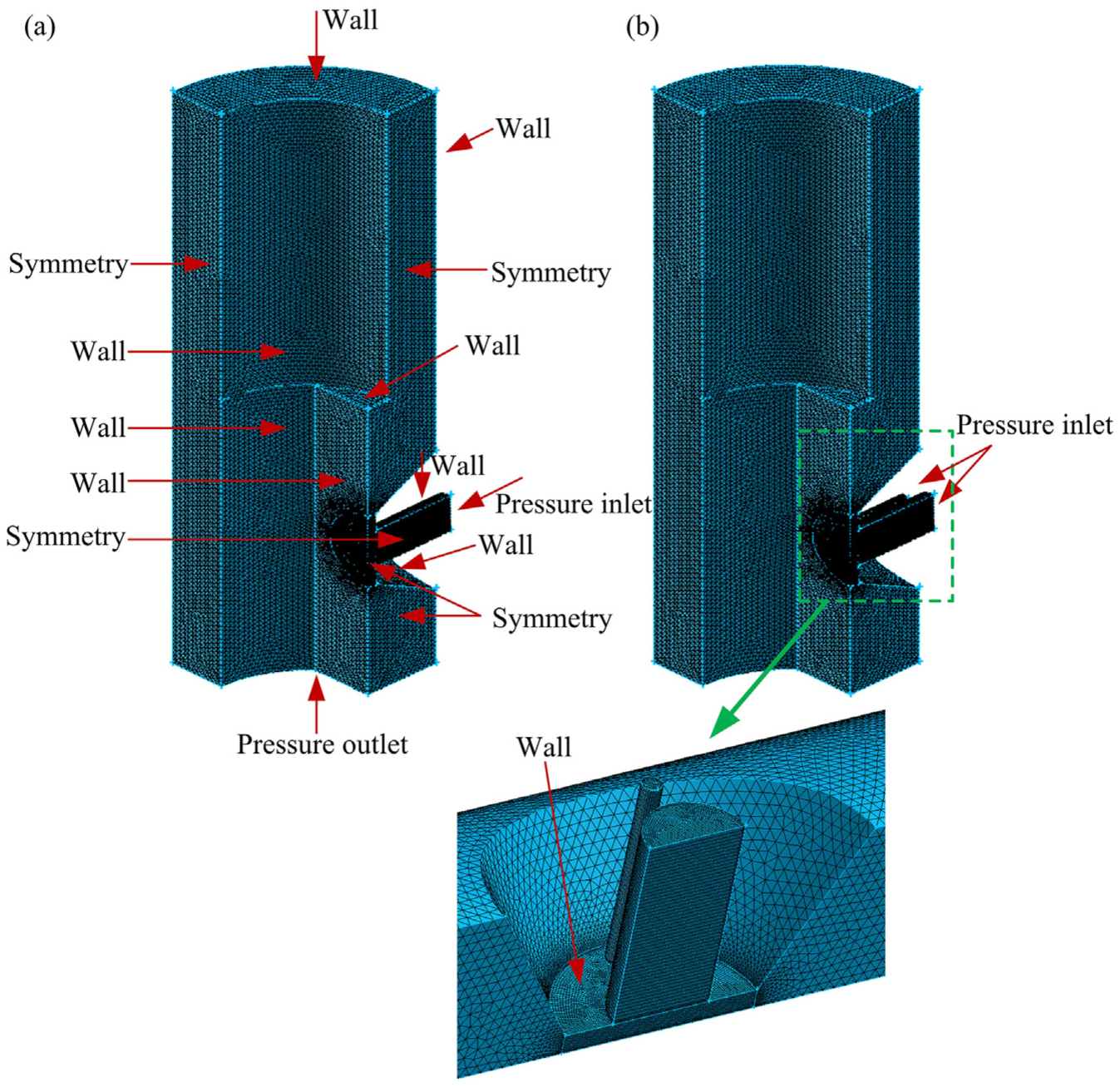
Mesh and boundary conditions of the computational domain: (a) without minijet and (b) with minijet.
The mesh quality has a great effect on the calculation accuracy.17,18 In this work, a hybrid scheme of the hexahedron and tetrahedron elements is proposed for meshing. Specifically, the structured hexahedron elements are used for the regions of minijet, main jet and the slot between the flapper and the nozzle while the tetrahedron and unstructured hexahedron grids are applied for other regions (Figure 3). To ensure the accuracy, 10 grid layers are meshed in the slot. A fixed-type size function is applied for generating the tetrahedron and unstructured hexahedron grids. The skewness value of the meshes is less than 0.74 and thus the mesh quality is acceptable. 19 Considering the possible effect of mesh size on the simulation accuracy, 20 grid independence analysis has been conducted and thus the maximum cell size adopted is of 0.06 mm in this work.
Four types of boundary conditions are included in the computational domain (Figure 3). The static pressure condition is defined at the inlet of the nozzle and the outlet of the flapper-nozzle stage. The inlet pressure inlets are set from 5 to 12 MPa, while the outlet pressure is zero, that is, gauge pressure. The symmetry condition is used for the symmetry planes, and the wall-type boundary is given for other surfaces. For the convenience of discussion, the flapper surfaces are divided into four parts, that is, FS1, FS2, FS3, and FS4.
Governing equations and solving strategies
The governing equations of a two-phase flow mixture model consist of continuity equation, momentum equation, and vapor transport equation. A preliminary simulation has been conducted to examine the effect of the standard, RNG and Realizable k-ε models, which shows that a negligible variation (≤0.32%) of mass flow rate among different turbulence models. This is consistent with previous investigations on flow simulation for hydraulic valves.9,21 Thus, to reduce computational time, the standard k-ε model is chosen for solving turbulence kinetic energy equation and turbulent dissipation rate equation, as employed in previous studies.6,12,13,19,22–24 And the Singhal et al. model is applied for calculating vapor mass fraction, as used in previous studies.12,13,19,22
The governing equations are calculated using pressure-based solver. The SIMPLEC and PRESTO! schemes are applied for the pressure-velocity coupling and pressure discretization, respectively. The QUICK scheme is chosen for solving the vapor transport equation while the first order upwind is applied for calculating the momentum, turbulent kinetic energy and turbulent dissipation equations. The properties of the hydraulic fluid are listed in Table 1.
The properties of the hydraulic fluid.

Experimental validation
To validate the numerical results, the mass flow rate of the flapper-nozzle structures at different inlet pressures are experimentally investigated and then compared with numerical results, as did by previous investigations on hydraulic valves.9,10 The hydraulic circuit includes hydraulic pump, control valve, pressure gauge, flowmeter and flapper-nozzle assembly (Figure 4(a)). The flow rate of the pump is of 2.9 L/min at rated pressure of 21 MPa. The pressure is adjusted by control valves and measured by the pressure gauges with an accuracy of ±1.6%. The pressure gauges at the upstream and downstream of the flapper-nozzle structure have a measuring range of 0–16 MPa and 0–1 MPa, respectively. The flow rate is measured by a flowmeter with a measuring range of 0–150 L/h and an accuracy of ±1.5%. The flapper-nozzle structure consists of a flapper, flapper holder, two nozzles, nozzle holder, front and back covers (Figure 4(b)). The flapper and nozzles are fabricated by computer numerical control machines and the fabrication error in the dimensions of the flapper and nozzles is less than 0.02 mm. For easy fabrication of the small holes, each nozzle with two minijets is divided into two parts, that is, head-ends (smaller parts) and back-ends (larger parts), as shown in Figure 4(b). The head-ends of two nozzles are adhered on the nozzle holder after the gap between them is adjusted to 1.9 mm. A rectangular cylinder with the dimension of 1.9 mm × 2 mm is inserted into the central chamber of the nozzle holder, to assist the gap adjustment between two nozzles. The flapper is placed at the center of the two nozzles, through regulating the relative position between flapper holder and the nozzle holder under the vision of a microscope. During each measurement, a stable flow condition is achieved before recording the mass flow rate.

Experimental setup: (a) hydraulic circuit, (b) flapper-nozzle assembly and (c) geometry of the nozzle with two minijets.
Figure 5 compares the simulated and experimental mass flow rates under different inlet pressure Pin. Two observations can be made. First, the mass flow rates for the traditional nozzle and the nozzle with the minijets present a similar tendency, suggesting a qualitatively unchanged relation between the mass flow rate and the inlet pressure. Second, the relative deviation between the simulated and experimental mass flow rates for the traditional nozzle and the nozzle with minijets is less than 4.2% and 7.9%, respectively. This indicates a good agreement between them. Thus, the hybrid mesh and simulation settings are reasonable for numerical modeling of the flapper-nozzle structure.
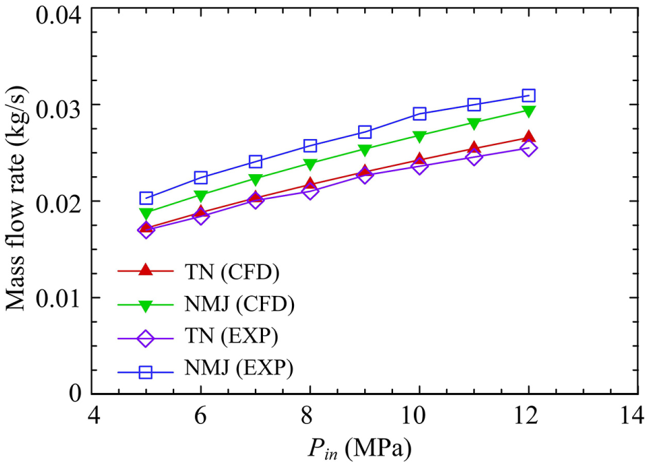
Mass flow rate of the outlet in the flapper-nozzle structure.
Results and discussions
Cavitation reduction
To explore the cavitation reduction in detail, vapor fraction contours in two orthogonal planes are examined, that is, the cross-sectional planes at z/H = 0.25 and θ = 45°. Figure 6 shows the vapor fraction contours in the cross-sectional plane of z/H = 0.25. In case of the traditional nozzle, the cavitation occurs in three regions, that is, the annulus between the housing wall and flapper, flapper surface and nozzle tip. As Pin rises from 5 to 7 MPa, the vapor fraction exhibits a remarkable increase in the annulus, suggesting that cavitation is greatly enhanced. This is consistent with previous study of cavitation in the diesel nozzle by Qiu et al. 25 At Pin = 9 MPa, the area of the vapor further increases, almost occupying the right half of the annulus. Further at Pin = 11 MPa, the vapor starts to occur in the left half of the annulus. In the flapper-nozzle stage with the minijets, the vapor fraction is greatly reduced. At Pin = 5 MPa, the cavitation on the nozzle tip and the curved surface of the flapper are suppressed and the cavitation in the annulus is eliminated. As Pin goes up to 7 MPa, the area of the cavitation on the nozzle tip and the flapper surface is enlarged, and the cavitation in the annulus can be observable. In spite of this, cavitation is still strongly reduced, compared to that of the traditional nozzle. Further increase to 11 MPa, although the cavitation on the nozzle tip exhibits an increase along the cone wall, the cavitation in the left half of the annulus is still absent.

Vapor fraction contours in the cross-sectional plane of z/H = 0.25: (a) traditional nozzle and (b) nozzle with the minijets.
Figure 7 presents the vapor fraction contours in the cross-sectional plane of θ = 45°, which cuts through the cavitation on the flapper surface and that in the annulus shown in the cross-sectional plane of z/H = 0.25 (Figure 6(a)). For the traditional nozzle, the cavitation on the flapper surface and that in the annulus can be observable at Pin = 5 MPa. As Pin rises from 5 to 9 MPa, the area of the vapor fraction is evidently enlarged, especially for that in the annulus. A further increase in Pin to 11 MPa, the cavitation in the annulus mainly grows along the z direction, probably due to the space contraction in the r direction. For the nozzle with the minijets, the cavitation in the annulus is absent at Pin = 5 MPa. As Pin increases from 7 to 11 MPa, it becomes visible and is enhanced. Nevertheless, the vapor fraction in the annulus is evidently suppressed, indicating the effective cavitation reduction by the minijets.

Vapor fraction contours in the cross-sectional plane of θ = 45°: (a) traditional nozzle and (b) nozzle with the minijets.
Lateral velocity
To explore the possible mechanism behind the cavitation reduction, Figure 8 presents the velocity contours and streamlines in the cross-sectional plane of z/H = 0.25. The flow structure in the traditional flapper-nozzle stage can be identified as the combination of the impinging jet flow and the radial jet flow. 22 The radial jet from the stagnation region moves out of the slot between the flapper and the nozzle, and then impinges upon the housing wall. After that, the jet deflects along the wall, forming wall jets further downstream. 26 Finally, the jet flow reattaches to the flapper surface and nozzle wall, forming flow structures with anti-clockwise rotation on the left side and clockwise rotation on the right side, respectively. Once the minijet is introduced, the radial jet velocity exhibits a substantial drop, especially in the annulus region. The jet impingement upon the housing wall is absent and consequently the rotating flow structures are suppressed. Note that the locations of the rotating structures occur coincide with those of the vapor for both the traditional nozzle and the nozzle with minijets. This indicates that the suppression of the rotating structures by the reduced radial jet velocity may be responsible for the remarkable cavitation reduction.

Velocity contours and streamlines in the cross-sectional plane of z/H = 0.25 (Pin = 7 MPa): (a) traditional nozzle and (b) nozzle with the minijets.
Static pressure distributions on the flapper surfaces
Figure 9 presents the static pressure distributions on the flapper surfaces at Pin = 7 MPa. The pressure distributions are qualitatively the same between the traditional nozzle and the nozzle with the minijets. However, there are three relative small differences between the traditional nozzle and the nozzle with the minijets. First, the static pressure on surface FS1 exhibits an increase in a small area beside the stagnation region caused by the main jet. This is apparently due to the impingement of the minijet flow. Second, the area of the negative pressure on the surface FS2 is slightly expanded under the effect of the minijets. Third, the positive pressure on the surface FS3 for the nozzle with the minijets increases slightly, compared to that for the traditional nozzle.

Static pressure distributions on the flapper surfaces at Pin = 7 MPa: (a) traditional nozzle and (b) nozzle with the minijets.
The lateral flow forces on the flapper
Since the lateral flow forces on the flapper directly affect the flapper deflection and thus the hydraulic output of the servo-valve, 6 it is of great importance to examine the variation of the lateral flow forces under the effect of the minijets. Due to the neglectable flow forces on the surface FS4, the following discussions will focus on the forces on the surfaces FS1, FS2 and FS3.
Figure 10(a) presents the lateral flow forces on the surface FS1. In case of the traditional nozzle, the flow forces in both drag and lift directions exhibit a linear rising trend with the increasing inlet pressure. Note that the drag force is greatly larger than the lift force. In fact, the drag force is due to the jet impingement issuing from the nozzle, which produces a high-pressure region on the flapper surface (Figure 9(a)). In contrast, the lift force on the flapper surface FS1 results from the shear force of the flow. In case of the nozzle with the minijets, the variation of the flow forces in both drag and lift directions remains linear. However, the drag forces are slightly larger than those of the traditional nozzle with the variation of 4.89% ∼7.47% over the range of 5 MPa ≤ Pin ≤ 12 MPa. This increase comes from the impingement of the minijet flow. In contrast, the lift forces are marginally lower than those of the traditional nozzle. This can be ascribed to the reduced velocity of the radial jet (Figure 8).
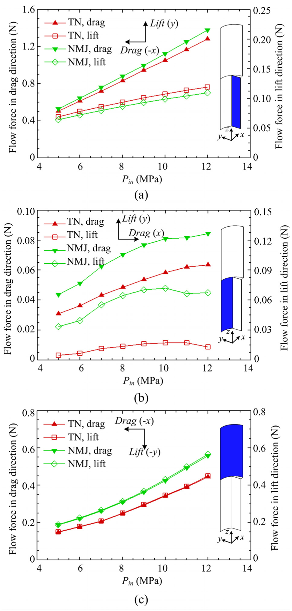
Lateral flow forces on the flapper surface: (a) FS1, (b) FS2 and (c) FS3.
The lateral flow forces on the surface FS2 are governed by the reattachment of the radial jet (Figure 8) and the negative pressure (Figure 9). The former produces push forces while the latter generates pull forces. As shown in Figure 10(b), the overall effect of flow on the surface FS2 is to generate a pull force, suggesting the negative pressure dominates the flow impact on the surface FS2. Moreover, the flow forces in drag direction is larger than those in lift direction. This may due to that the lift forces are the difference between the push effect caused by flow reattachment and the pull effect induced by the negative pressure. Under the effect of the minijets, both the drag and lift forces are amplified by an average value of 39.7% and 394%, respectively. This is due to the increased area of the negative pressure on the surface FS2 (Figure 9). And the increase of the lift forces is much larger than that of the drag forces, due to the suppression of the flow reattachment.
The lateral flow forces on the flapper surface FS3 are shown in Figure 10(c). In case of the traditional nozzle, the impact of the flow forces on the surface FS3 is to generate push forces. This can be ascribed to the positive pressure on the surface FS3 (Figure 9(a)). Moreover, the flow forces in both the drag and lift directions increase with the rising inlet pressure. And the magnitude of the drag and lift forces are equivalent to each other. In case of the nozzle with the minijets, the flow forces exhibit a similar variation trend with the increasing inlet pressure, compared to those for the traditional nozzle. However, the drag and lift forces are increased by average values of 25.3% and 25.7%, respectively. This is apparently due to the rising pressure on the surface (Figure 9).
Conclusion
This work presents a numerical investigation on cavitation and flow forces of the flapper-nozzle pilot valve with continuous minijets. Mass flow rate measurements are conducted to validate the numerical simulation. The flow characteristics of the flapper-nozzle stage with and without minijets at null clearance are compared in detail at the inlet pressure of 5–12 MPa. The main conclusions may be drawn as follows.
The vapor fraction in two orthogonal planes of the flapper-nozzle stage is significantly reduced by the minijets, suggesting an effective method for cavitation reduction. The suppression of the rotating structures in the annulus caused by the reduced radial jet velocity may be responsible for the cavitation reduction.
The variation trend of the flow forces with the inlet pressure remains unchanged while the magnitude of the flow forces is varied slightly under the effect of the minijets. First, the flow forces on the surface FS1 are increased in drag direction but reduced in lift direction. This can be ascribed to the minijet impingement and the reduced radial jet velocity, respectively. Second, the flow forces on the surface FS2 are amplified in both the drag and lift directions, due to the increased area of the negative pressure and the suppression of the radial jet reattachment. Third, the increase in positive pressure enlarges the lateral forces on the upper surface FS3.
Thus, this work presents a numerical investigation on flow characteristics of the flapper-nozzle pilot valve under the effect of continuous minijets. Numerical results have shown that the minijets could reduce cavitation in the region between the flapper surface and the housing wall, even at large inlet pressure. Further studies are required to experimentally investigate the flow characteristics of the servo valves with continuous minijets and further explore the method to reduce the cavitation at the nozzle tip.
Footnotes
Handling Editor: Hongwei Wu
Declaration of conflicting interests
The author(s) declared no potential conflicts of interest with respect to the research, authorship, and/or publication of this article.
Funding
The author(s) disclosed receipt of the following financial support for the research, authorship, and/or publication of this article: The financial support given to H.Y. from Zhejiang Provincial Natural Science Foundation of China under grant No. LQ19E050013 and the Scientific Research Startup Fund of Hangzhou Dianzi University through grant No. KYS015618005.