
Abstract
In this article, the improvements on vibration isolation performance of hydraulic excavators are achieved via the optimization of powertrain mounting system. The powertrain is viewed as a rigid body and described by a 6-degree-of-freedom model. The rigid-flexible coupling model of hydraulic excavators is carried out based on software ADAMS, in which the influences from the mass and elastic deformation of base are considered. In the process of optimization for the powertrain mounting system, energy decoupling rate and vibration transmissibility are set to be the objective functions, while the stiffness coefficients in three directions of the mounting coordinate systems are chosen as the designed variables. With the given constrained conditions of these variables, nondominated sorting genetic algorithm II is employed to optimize the stiffness coefficients of suspension elements. The simulations for the rigid-flexible coupling model with the optimized mounting system show that the vibration isolation performances of hydraulic excavators are improved comparing with that with non-optimized powertrain mounting system.
Keywords
Introduction
With the applicability to various types of situations, hydraulic excavators are widely used in civil and construction industries, which are about 1.6 million in China in 2015. 1 Due to the ever-increasing size and complexity of construction sites, the demand for the hydraulic excavators is expected to continue increasing in the near future. The control techniques of the vibrations and noises are very important for the performance improvement of hydraulic excavators. Serious vibrations of the hydraulic excavator will shorten the service life of powertrain, reduce the working efficiency and reliability. The looseness of engine base, the breakage of engine mounting bracket, and the leakage of hydraulic oil are common faults caused by the vibrations of a hydraulic excavator. Excessive vibrations will induce the high-level noises, which not only deteriorate the operating conditions of the equipment in hydraulic excavators, but also have the unhealthy impacts on the operators in the cabin. On the other hand, vibrations and noises of hydraulic excavators will decrease the energy efficiency and result in a huge waste resources and serious environmental pollutions.
Powertrain is one of the main resources of vibrations and noises for excavators, which is the primary system to investigate for vibration and noise reduction of excavators. The powertrain and the base are connected by the suspension elements (SEs) between them. In general, the mounting system has the effects of supporting, position limits, and vibration isolation. The powertrain is supported by the SEs with suitable distributions of the loads from its gravity and driving counter torque. With the non-steady excitations of operating conditions, the mounting system can control the motions of powertrain, prevent the collisions and interference with other components. Most importantly, the mounting system isolates the vibrations from powertrain to transmit to the base and cabin of excavators, which also depress the shocks and vibrations from the excitations of ground and braking to hurt the powertrain. Then, the design of the mounting system is critical for the control of vibrations to improve the performance of hydraulic excavators. It will determine the levels of vibrations and the comfort of operation for hydraulic excavators.
In recent years, the interests in designing the powertrain mounting system are mainly based on decoupling theories.2–4 In most studies, the powertrain is modeled as a rigid body with 6-degree-of-freedom (DOF) model and one end of the SEs is assumed to connect with rigid or flexible bases. The designed targets are to restrict the natural frequencies of a powertrain to prescribed ranges, to maximize the mode energies in each decoupling coordinates, and to minimize the transmitted forces from engine to the base. Typical works in this aspect are reported in previous works.5–11 Singh and colleagues6–8 proposed analytical methods of decoupling automotive powertrain based on the concept of torque roll axis with the rigid or flexible base. Ashrafiuon 9 and Ashrafiuon and Nataraj 10 established the dynamic equations for a powertrain mounting system considering the flexibility of the ground and carry out optimization of an aircraft engine mount by minimizing the transmitted forces to the base. Similar to the work of Ashrafiuon 9 and Ashrafiuon and Nataraj, 10 Swanson et al. 11 developed the method aim to engineering applications. To depress the vibration for a city bus, El Hafidi et al. 12 used a 6-DOF model for powertrain mounting system and determined the optimal positions of engine mounts using the decoupling theories and minimized transmitted forces. Lee et al. 13 discussed the flexible chassis on the dynamic responses of a powertrain. However, few works are reported for the design and optimization of the powertrain mounting system in hydraulic excavators.
The contribution of this article is to develop a method to improve the vibration isolation performance of hydraulic excavators via the optimization of powertrain mounting system. The powertrain is also described as a rigid body with 6-DOF model. Considering the important influences of the mass and elastic deformation of base on the vibration isolation performance, the rigid-flexible coupling model of a hydraulic excavator is built by the software based on finite element method (FEM). The optimization procedure of the powertrain mounting system is given as follows. The stiffness coefficients in three directions of the mount coordinate system are chosen as the designed variables, and energy decoupling rates and vibration transmissibility are used as the objective functions. With the given constrained conditions of the designed variables, nondominated sorting genetic algorithm II (NSGA-II) 14 is employed to optimize the stiffness coefficients of SEs. The rigid-flexible coupling model with the optimized powertrain mounting system is simulated to calculate the vibration isolation transmissibility (VIT) of the hydraulic excavator. Comparing with the hydraulic excavator with non-optimized powertrain mounting system, the vibration isolation performances of the hydraulic excavator are improved within the working speed range.
Models for analysis of the vibration isolation performance of hydraulic excavators
The mathematical models for the motions of powertrain
Figure 1 illustrates a 6-DOF model of the powertrain mounting system in hydraulic excavators. With the assumptions of small motions, the powertrain is modeled as a rigid body of time-invariant inertia matrix of dimension 6. 7 The powertrain is supported by four mounts on the base of hydraulic excavators, and the dynamic model of a mount element is given in Figure 2.

The 6-DOF model of powertrain mounting system.
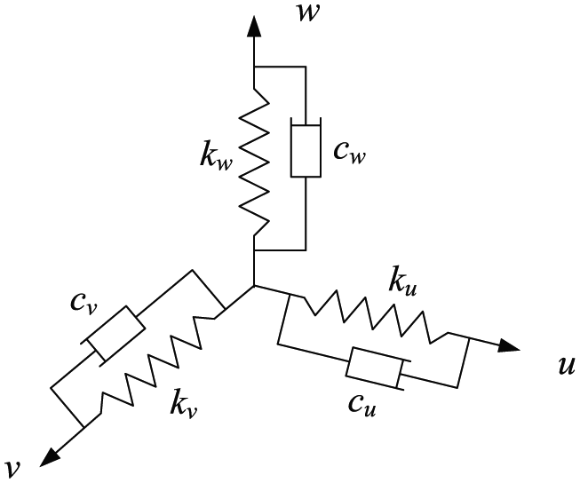
Dynamic model of a mount element.
Each of mount elements is described by a set of three tri-axial spring elements, and the stiffness values are assumed to be insensitive and spectrally invariant to the excitation amplitudes.
15
The following coordinate systems are used to describe the motions of the powertrain mounting system: inertial coordinate
The Lagrange equation for the motions of powertrain can be given as follows

where

where

Assume that there are
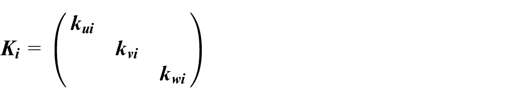
where stiffness matrix
Because of the damping effect, the dissipated energy

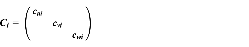
where damping matrix


Substituting equations (2)–(4) into equation (1), the governing equation for the motions of powertrain is

where
If no external force is employed to excite the powertrain, the following free vibration equation can be obtained by neglecting the damping

Based on

where
Then, the kinetic energy on the

where

Finite element model for powertrain mounting system
The powertrain is one of the main sources of vibrations and noises of hydraulic excavators. To simulate the vibration isolation performance of hydraulic excavators, a dynamic analysis model of powertrain with the mounting system is carried out with the well-known commercial software SolidWorks and ADAMS based on FEM. After a simplified procedure for the complex structures, the powertrain model obtained in SolidWorks is given in Figure 3, where the used parameters are shown in Table 1. The coordinates of SEs in the inertial coordinate system

The powertrain model in SolidWorks.
The parameters of powertrain.

The coordinates of SEs (mm).

SE: suspension element.
The dynamic stiffness coefficients are used to calculate the natural characteristics of the mounting system. With the changes of amplitudes and frequencies of excitations, the dynamic stiffness coefficients will vary in different working conditions. The dynamic stiffness coefficients in Table 3 are chosen for the simulations of the powertrain mounting system in this article. The damping ratio is another parameter for the dynamic model of mount elements. Its variances will have little impacts on the changes of natural frequencies of SEs in mounting system. Then, constant damping ratios are considered in the dynamic model of mount elements. Specifically, the damping ratios of the SEs 1 and 2 are chosen as 0.12, while that of SEs 3 and 4 are 0.1. The mounting angles are set to be 45° for SEs 1 and 2 and 0° for SEs 3 and 4. 16
The dynamic stiffness coefficients of SEs (N/mm, static and dynamic ratio: 1.4).

SE: suspension element.
Using the Parosolid type of the three-dimensional model in SolidWorks, a FEM model can be generated by the software ADAMS (Figure 4). Neglecting the mass of SEs (relative to the mass of powertrain), only the principal compressive stiffness and damping are considered in the FEM model, in which the SEs are realized by the bushing forces. According to the coordinates in Table 2, the Marker points are established and then the FEM model for simulations of dynamics of powertrain with four SEs is given in Figure 5.
The powertrain model in ADAMS.

The ADAMS model of powertrain with the mounting system.
In our previous paper, 16 the natural frequencies of powertrain were compared based on the numerical calculations of equation (5) by MATLAB and simulations of the ADAMS model of powertrain mounting system. Only small errors exist in the results of natural frequencies and it declares the reliability of ADAMS model of the powertrain mounting system. Furthermore, dynamical response analysis in time and frequency domains is conducted to verify the vibration isolation performance of the mounting system to the powertrain of a hydraulic excavator.
Finite element model of the hydraulic excavator
The mass and elastic deformation of the base in hydraulic excavators will have important influences on the vibration isolation performances of the mounting system. Response analysis based on the ADAMS model of powertrain with a mounting system by neglecting these factors lead to underestimate or misestimate the effects of the mounting system. In this section, a FEM model for a hydraulic excavator is established to analyze the vibration isolation performance of the mounting system. The used parameters of the hydraulic excavator are provided by a manufacturer of hydraulic excavators. The simplified complex structures and the powertrain are assembled in the 3D model of the hydraulic excavator (Figure 6).

The 3D model of a hydraulic excavator.
With the restrictions of the software ADAMS to flexibility of the complex components in the hydraulic excavator, ANSYS is employed to carry out the flexibility of the base. A MNF file of ANSYS will be exported and used to substitute the rigid body in ADAMS model to obtain the compliant base. The main procedure of flexibility contains the following steps: (1) importing the three-dimensional geometry models of components into ANSYS, and defining the material properties and the type of elements for simulations, (2) establishing the key points to define the kinematic pairs between the components, which can transform to be the marker points in software ADAMS, (3) generating the meshes of the components and key points, (4) establishing the area connected to the mounting elements by key points to be the rigid area, and (5) exporting the MNF file. The established rigid area is given in Figure 7.

The established rigid area.
The ADAMS model of the powertrain and the mounting system are integrated with the base, and the same coordinates of the mounting system are used to build the rigid-flexible coupling model for the entire hydraulic excavator with substituting the rigid components by MNF file from ANSYS (Figure 8).

The rigid-flexible coupling model of the hydraulic excavator.
Free vibration analysis of the rigid-flexible coupling model is conducted, and the natural frequencies and energy decoupling rates are obtained to verify the effectiveness of the model. The results are compared with that of the 6-DOF model of equation (5), which are shown in Tables 4 and 5, respectively.
Comparisons of the natural frequencies with 6-DOF model.

DOF: degree-of-freedom.
Comparisons of the energy decoupling rate with 6-DOF model.
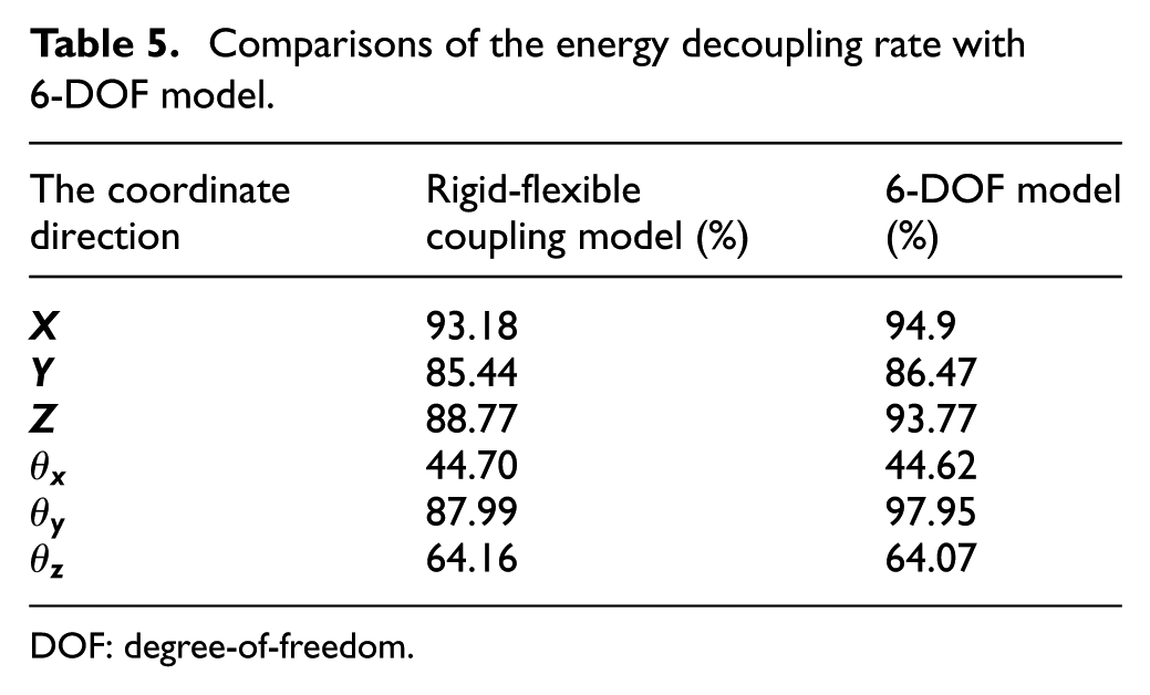
DOF: degree-of-freedom.
It can be found that the maximum errors of the natural frequencies in Table 4 are less than 0.7 Hz. The errors of energy decoupling rates in Table 5 are less than 5% mostly. However, the energy decoupling rates on the coordinate
The improvement on vibration isolation performance of hydraulic excavators with optimized powertrain mounting system
In engineering measurement, VIT is often used to evaluate the vibration isolation performance of mounting systems, which is defined to be the ratio of the amplitudes of inputs and measured responses. It can be computed as

where

where
Vibration isolation performance with non-optimized powertrain mounting system
Within the working speed range (1000–2050 r/min) of the powertrain, equation (11) is employed to calculate the vertical VITs of four suspension components (Figure 9). It can be seen from Figure 9 that the VITs of the SEs 2, 3, 4 are stabilized in the idle condition and all are larger than 20 dB. Although the VIT of SE 1 keeps steady at the high working speed (larger than 20 dB), however, it is smaller than 20 dB in the idle condition (1000 r/min). Overall, the mounting system in the hydraulic excavator has certain vibration isolation performance to block the transmissibility of the vibrations from the powertrain. However, other than its stabilization on the high working speed, the VIT of SE 1 does not satisfy the requirements of vibration isolation in the idle condition. It needs to be improved by optimization.
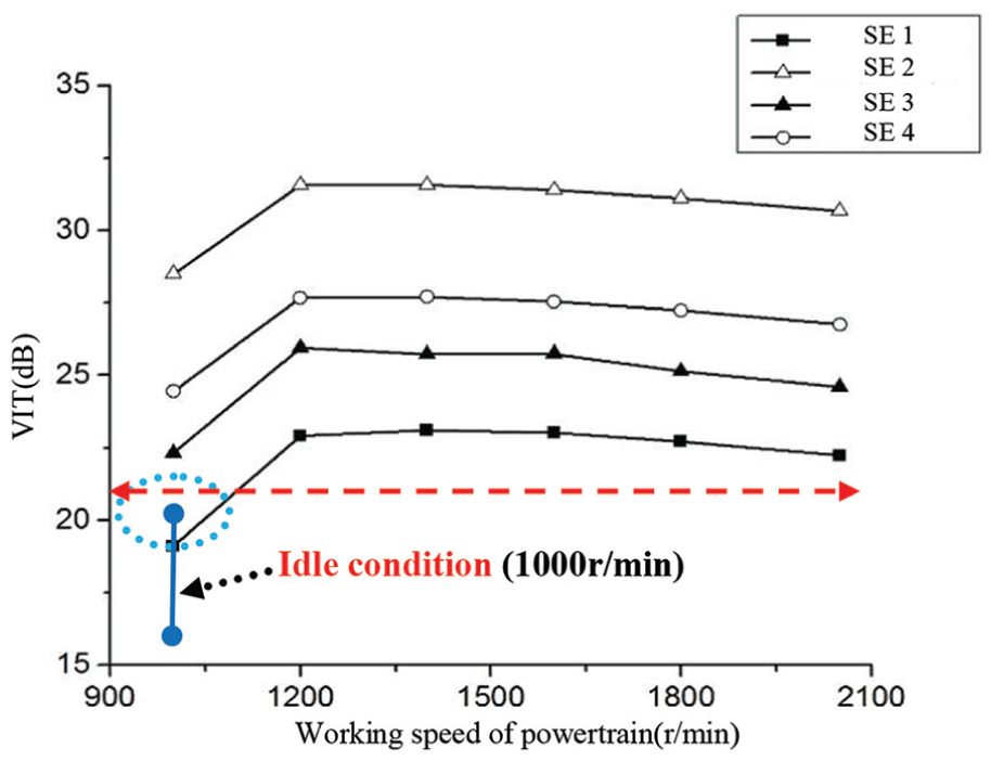
The vertical VITs of four suspension components.
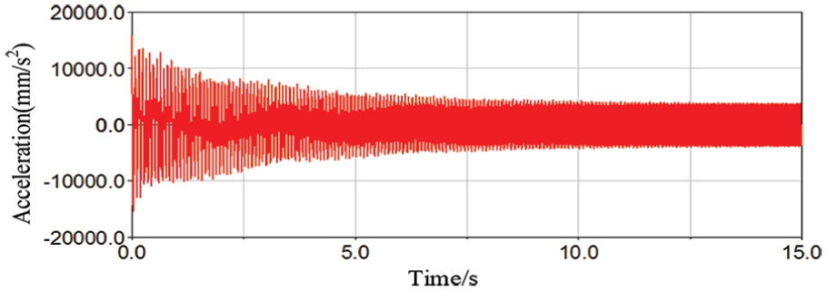
In order to illustrate the effects of the optimized powertrain mounting system, the rigid-flexible coupling model of the hydraulic excavator (Figure 8) is used to analyze the vibration isolation performance of the mounting system in the idle condition. The 6-DOF model is also used to simulate the acceleration curves of the engine and base, which defines the base to be a rigid body. The acceleration curves of the powertrain and base on the SE 1 are obtained to investigate the effects of the mounting system. Because of the assumption of rigid body on the base, the acceleration of the base on the position SE 1 is 0, and then it is impossible to obtain the VITs of the mounting elements based on the 6-DOF model. It is noted in Figures 10 and 11 that the rigid-flexible coupling model–based acceleration curve of the engine on the position of SE 1 has the obvious attenuation on that base on the 6-DOF model.
The 6-DOF model based acceleration curve of the engine on the position of SE 1.

The rigid-flexible coupling model–based acceleration curve of the engine on the position of SE 1.
Optimization procedure for the powertrain mounting system
To optimize the powertrain mounting system, the software ISIGHT integrated with MATLAB and ADAMS is used to implement the optimization process (Figure 12). The stiffness coefficients of the mounting elements are set to be the designed variables; the constrained conditions are the limits of the ratios of natural frequencies and SE’s stiffness coefficients. The energy decoupling rate and vibration transmissibility are considered to be the objectives; the vibration isolation performance can be improved via optimization by the following process in ISIGHT.

The optimization process of the mounting system.
The designed variables
The designed variables are defined to be the stiffness coefficients of the SEs. Twelve designed variables are added into the compounds: Parameters in MATLAB, which can be given as follows

The objective functions
Two objective functions are established to implement the optimization process. The maximum energy decoupling rate on the six coordinates of the mounting system is assigned to be the first objective function

where
The

where
The constraint conditions
In the manufacturing process of SEs, the shear-compression ratios of rubber material are often set to be
Moreover, the constrains of working conditions require that first natural frequency is larger than 5 Hz, and the highest natural frequency should be smaller than 35.35 Hz (from the vibration isolation theory,
17
the natural frequencies should be controlled to less than
The constrained range of the natural frequencies.

The optimization algorithm
The NSGA-II is an improved genetic algorithm for multi-objectives, which is suitable to obtain the solutions of multi-objective optimization problem. 14 The used parameters of NSGA-II are given in Table 7.
The parameters of NSGA-II.

NSGA-II: nondominated sorting genetic algorithm II.
The results of vibrations performance for the powertrain mounting system
The results of optimization for the powertrain mounting system such as the suspension stiffness coefficients, the natural frequencies and energy decoupling rates are given in Tables 8–10, respectively. From Table 8, the natural frequencies are all constrained into the proper range, which satisfy the requirements of the vibration isolation. After the process of optimization, the energy decoupling rates on the coordinates
The suspension stiffness coefficients after optimization (N/mm).
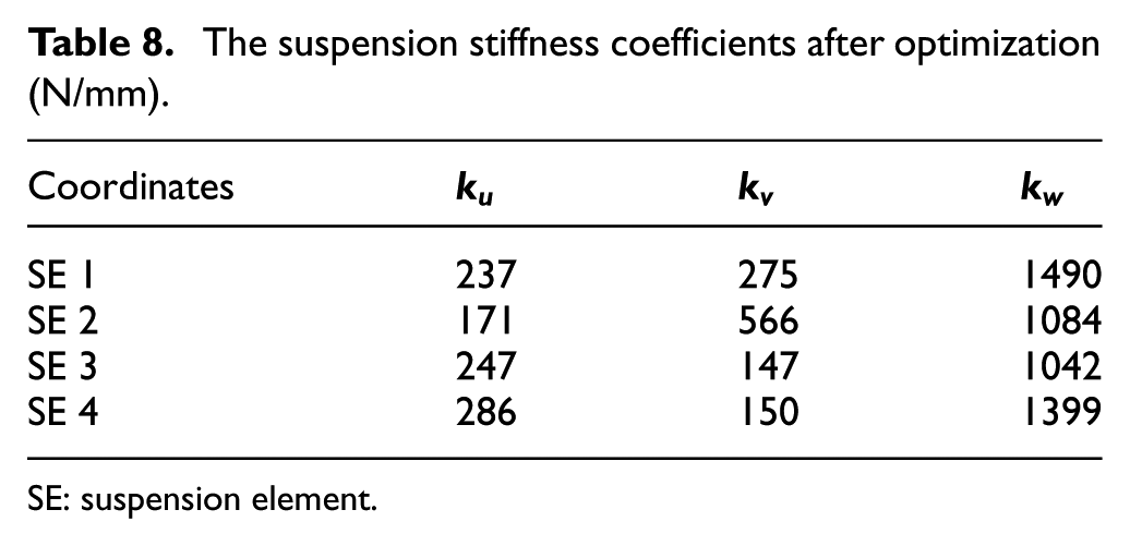
SE: suspension element.
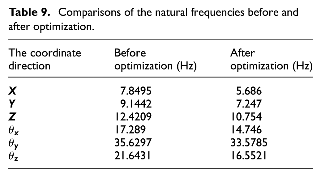
Comparisons of the natural frequencies before and after optimization.
Comparisons of the energy decoupling rates before and after optimization.

Figures 13 and 14 are the steady-state response curves of support forces of the suspensions and the vibration transmissibility before and after the optimization process, respectively. After the optimization process for the suspension system, the amplitudes of the steady-state responses of the mounting support force reduce greatly from that before the optimization process. On the other hand, the vibration transmissibility of the mounting system also decreases to 69% from 72% before the optimization procedure. The results show that the optimization procedure can improve the vibration isolation performance of the mounting system onto the powertrain.
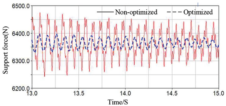
The steady-state response curves of support force of the suspension before and after optimization.
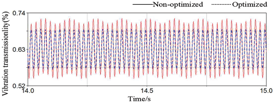
The vibration transmissibility of the mounting system before and after optimization.
Vibration isolation performance with optimized powertrain mounting system
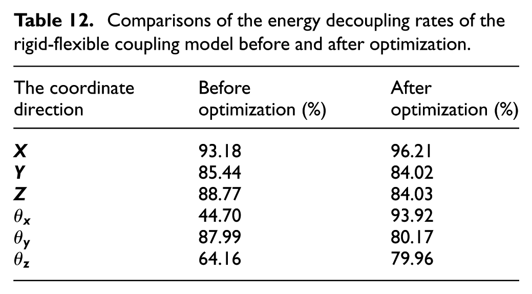
New stiffness coefficients of SEs are obtained in Table 8 by the optimization procedure for the mounting system of powertrain. Using the obtained stiffness coefficients, the rigid-flexible coupling model is employed to simulate the dynamics of the hydraulic excavator. The natural frequencies (Hz) and the energy decoupling rates (%) are calculated and compared in Tables 11 and 12, respectively. The natural frequencies of rigid-flexible coupling model satisfy the requirements of the vibration isolation. It can also be found that the energy decoupling rates on the coordinates
The natural frequencies of the rigid-flexible coupling model before and after optimization.

Comparisons of the energy decoupling rates of the rigid-flexible coupling model before and after optimization.
The rigid-flexible coupling model with the optimized stiffness coefficients of suspension elements is also employed to calculate the vertical VITs of the suspension components. The simulations are conducted in time domain; the vertical VIT is computed according to equation (11). It can be seen clearly in Figure 15 that vertical VITs are all larger than 20 dB. Especially, the vertical VIT of SE 1 after the optimization procedure is larger than 20 dB, while that of SE 1 before the procedure is smaller than 20 dB in the idle condition (1000 r/min). Then, the vibration isolation performance with optimized powertrain mounting system is satisfactory within the working speed range (1000–2050 r/min) of the hydraulic excavator. The optimization of the mounting system improves the vibration isolation performance of the entire hydraulic excavator.

The vertical VIT of four suspension components after the optimization procedure.
Conclusion
The improvements on vibration isolation performance of hydraulic excavators were conducted based on the optimization of powertrain mounting system. A 6-DOF model is used to describe the powertrain as a rigid body, and the rigid-flexible coupling model of a hydraulic excavator is built based on FEM with the considerations of the influences of the mass and elastic deformation of base. Energy decoupling rate and vibration transmissibility are the objective functions, while the stiffness coefficients in three directions of the coordinate systems of the mounts are chosen as the designed variables. With the constrained conditions for the designed variables, NSGA-II is employed to optimize the stiffness coefficients of SEs. After the procedure of optimization for the powertrain mounting system, optimized stiffness coefficients of SEs are used into the rigid-flexible coupling model to calculate the VITs of the hydraulic excavator. The results are compared with the hydraulic excavator with non-optimized powertrain mounting system. It can be concluded that the optimization of the mounting system can improve the vibration isolation performance of hydraulic excavators.
Footnotes
Handling Editor: James Baldwin
Author’s note
Mian Jiang is now affiliated with Foshan University, School of Mechatronics Engineering, Foshan, China.
Declaration of conflicting interests
The author(s) declared no potential conflicts of interest with respect to the research, authorship, and/or publication of this article.
Funding
The author(s) disclosed receipt of the following financial support for the research, authorship, and/or publication of this article: This project is supported by National Natural Science Foundation of China (grant nos 51775182, 51705147). The Natural Science Foundation of Hunan province (2018JJ3170) is also gratefully acknowledged.