
Abstract
The braking stability has significant importance for commercial vehicles, especially tractor-semitrailer. However, the brake lag of air brake system brings serious safety risk to the vehicle. To improve the braking stability of tractor-semitrailer, an optimized air brake system is proposed. Using characteristic of the fast exhaust response of spring brake cylinder of composite brake chamber, a normally open solenoid valve and a normally closed solenoid valve are connected with the spring brake cylinder of composite brake chamber of semitrailer to control the spring brake force, which responds more quickly than service brake force. A strategy is proposed to control the difference between the actual braking torque of the semitrailer brake and the target braking torque and is simulated based on AMESim and SIMULINK. An experiment is made to verify the effectiveness of the optimized system. The simulation shows that the improved scheme reduces the response time of semitrailer brake system by 0.19 s, and effectively restrains the lateral movement of the vehicle downhill braking and improves the stability of the braking direction of the vehicle. And the experiment indicates that the brake of semitrailer responds earlier than tractor, which means the brake lag is improved significantly.
Introduction
As a major road transport vehicle, tractor-semitrailers are often at full capacity, which proposes higher requirements of braking stability. Air brake system is often applied to tractor-semitrailer as primary braking system, because it can provide large braking force with small pedal force and short pedal stroke, meanwhile, using air as medium, there is no need to considering the issue of medium recovery, and the sealing requirements of the system is also lower than the hydraulic braking system. A typical air brake system contains pneumatic subsystem and mechanical system and includes air compressor, storage reservoirs, treadle valve, quick release valve, parking brake control valve, relay valve, brake chamber, and trailer control valve. 1
However, with the increasing speed of the modern vehicles, the braking load of the vehicle is also increasing, especially for the tractor-semitrailer, and the problem of excessive brake load is becoming more prominent. Tractor-semitrailers, often driven in mountainous areas, have to go long downhill. In order not to accelerate to a dangerous speed due to the action of its gravity, the vehicle needs brake continuously. 2 In addition, complex road conditions require frequent braking of different intensities. In these cases, long-time frequent work will not only make its temperature increase greatly, but also cause brake fade, and even the braking efficiency declines or fails completely. 3
The hydraulic retarder can be used to augment or replace some of the functions of primary friction-based braking systems. 4 It is usually used as an additional “assistance” to reduce speed, so that the main brake will achieve an increased life. Hydraulic retarders convert the kinetic energy of the vehicle into heat energy of the fluid. The oil is pumped into the working chamber, when retarder is required, and then the vanes, attached to the transmission driveshaft in the chamber, churn the oil to induce viscous drag to decelerate the driveshaft. The working oil will heat and circulate in the cooling system.
Due to the length of pneumatic tube and the response time of pneumatic components of air brake system, longer time is required for the compressed air to reach the brake chambers in semitrailer than in tractor, and the time difference is called brake lag. The brake lag makes semitrailer produce a braking force later than the tractor, which may cause an impact force between tractor and semitrailer and introduce unstable situations, 5 such as folding and drift, and these situations may lead to serious traffic accident. However, as the retarder could produce braking torque much faster than air brake system, which means tractors with hydraulic retarder brake earlier than those without hydraulic retarder, hydraulic retarder may make brake lag worse. Thus, it is significant to reduce or avoid brake lag.
Some research has been done with brake lag nowadays. Ma et al. 6 reduced the brake response time by optimizing the diameter of pneumatic pipe of the air brake system. He 7 optimized the parameters such as the exhaust space of the brake valve and the relay valve and the diameter of the pneumatic line to reduce the brake lag. Karthikeyan and Subramanian 8 proposed a proposal using an electronically controlled regulator instead of the foot valve to improve the braking response of the air brake system. Kumav et al. 9 shortened the time required for brake start-up by adding PID (proportional integral derivative) controllers based on the research of Karthikeyan P. Wang et al. 10 designed an electronic pneumatically controlled auxiliary brake device using a high-speed on–off valve. The device uses a PI controller output pulse width signal to regulate the open and close state of the high-speed on–off valve to control the brake chamber air pressure to reduce the response time of brake system. Zhu et al. 11 proposed a set of hysteresis compensation system for the brake lag of semitrailer. The system adds two inflation valves, two isolation valves, two exhaust valves, and two one-way valves to the original car air brake system, and electronically controls the inflation valve and the exhaust valve to overcome the brake lag. Qi et al. 12 proposed a hysteresis control method for pneumatic brake system based on closed-loop feedback. The controller was designed based on PID, and the feasibility and effectiveness of the scheme were verified by simulation. Lu 13 proposed to use the electronic control system to control the pneumatic brake system, and designed the trailer air brake electronic control system, thus achieving the optimization goal of the trailer brake coordination consistency. Rajaram and Subramanian 14 developed nonlinear controller for heavy commercial vehicle based on Lyapunov theory. The controller was tested and compared with a controller developed using a linear full state feedback controller. It was proved that the nonlinear controller has an advantage in terms of reduced brake delay.
Current techniques used to reduce brake lag can be broadly divided into four categories: improving the structure of pneumatic valve, optimizing the parameters of pneumatic components and pipe, adding high-speed switch valve, and applying PID controller. But hydraulic retarder is not considered when calculating the brake lag. In this article, an improved structure of air brake system is proposed to decrease the brake lag of tractor-semitrailer-equipped hydraulic retarder; the simulation and experiment are also made to verify the effect of the new structure.
The organization of this article is given as follows: in the next section, the improved scheme of air brake system is presented. Then the simulation model based on AMESim, SIMULINK, and TruckSim is developed. Next, the control strategy is proposed and developed in SIMULINK. Then the analysis of brake lag and lateral movement stability are made to validate the effectiveness of the optimized air brake system. And experiment is also made to verify the improved structure. Finally, conclusions regarding the presented study are given.
Introduction of the optimized air brake system
The semitrailer in this article is equipped with composite brake chamber, which is consisted of spring brake cylinder and service brake cylinder, and the exhaust speed of spring brake cylinder is much faster than inflating speed of service brake cylinder. So the service brake cylinder can produce faster if using the air from exhaust port of spring brake cylinder as input instead of original input at the begging of braking process. Plus, a normally open solenoid valve and a normally closed solenoid valve are added into air brake system to control the spring brake cylinder electronically, which can reduce the time to receive control signal significantly. Target braking torque of semitrailer is calculated by ECU (electronic control unit) (1) in accordance with the displacement of tractor brake valve mandrel and braking torque of hydraulic retarder, then the normally open solenoid valve (7) and normally closed solenoid valve (8) are powered on or off according to the difference between actual and target braking torque to control spring brake. The schematic diagram of the modified air braking system of semitrailer is shown in Figure 1.

Schematic diagram of the modified air brake system of semitrailer.
The normally open solenoid valve (7) and normally closed solenoid valve (8) are set in the inflating and exhausting circuit, respectively, and there are three working modes. First, if they are energized, the compressed air flows from spring brake cylinder into atmosphere through normally closed solenoid valve (8) and the braking torque rises. Second, if valves (8) and (7) are unenergized, the pressure of spring brake cylinder increases and the braking torque reduces. Third, if normally open solenoid valve (7) is energized and normally closed solenoid valve (8) is unenergized, the braking torque remains the same. By switching working modes, the spring brake can be used to produce braking torque for semitrailer to shorten the brake lag.
Simulation model
A simulation model of a semitrailer parking brake system is built in AMESim, mainly including solenoid valve model (since there is no normally closed valve in the software, a normally open valve is used instead), a relay valve model, a composite brake chamber model, a drum brake model, and the link unit to SIMULINK. The models are shown as Figures 2–4.

Relay valve model.

Composite brake chamber.
Drum brake model.
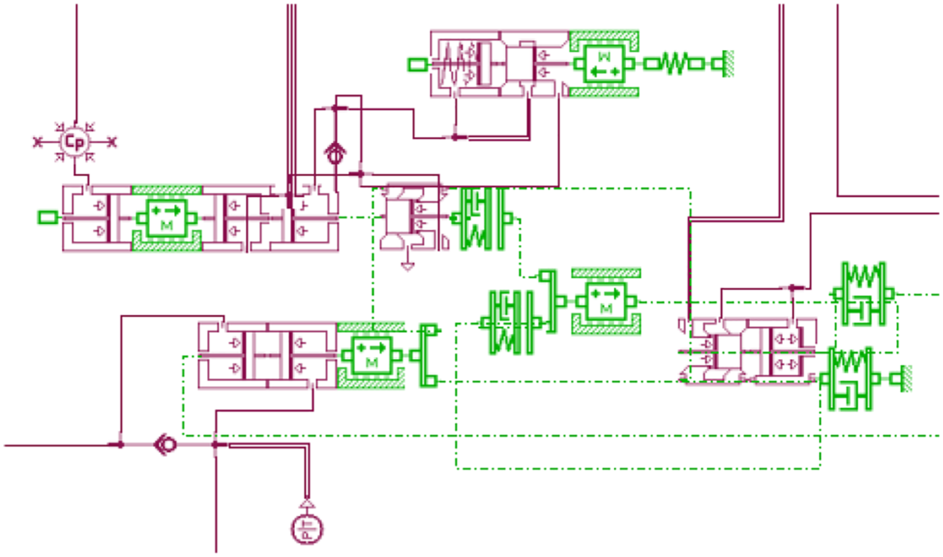
The variables input from the AMESim to the SIMULINK include braking torques of all brakes, filling rate of hydraulic retarder, pressure of spring brake cylinder, mandrel displacement of treadle valve, and the interaction force between the spring brake push rod and service brake push rod. Variables input from SIMULINK to AMESim include dynamic pressure of hydraulic retarder outlet port, depth and radius of fluid in hydraulic retarder circulating cavity, and control signal of solenoid valve. The model of the modified parking braking system of semitrailer is shown as Figure 5.

Simulation model of the modified parking braking system of semitrailer.
Other models of pneumatic valves of tractor-semitrailer are shown in Figures 6–9

AMESim model of series double chamber brake valve.
AMESim model of emergency relay valve.

AMESim model of the trailer control valve.

Flow chart of control strategy.
Control strategy
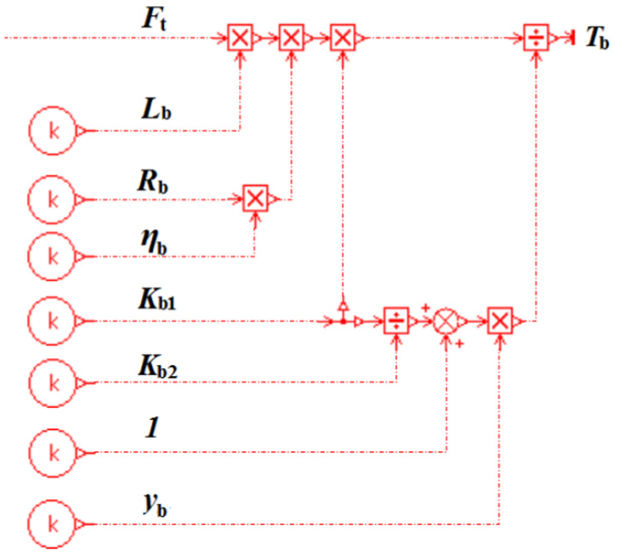
The strategy is aiming for controlling the difference between the actual braking torque of the semitrailer and the target braking torque to be within ± 100 Nm. First, determine the relationship between the pressure in spring brake cylinder and 0.275 kPa, and make sure the pressure is beyond 0.275 kPa. This is to reduce overheating and abrasion of energy storage spring, regulator rod, camshafts, and so on. So the air in the spring brake cylinder cannot be emptied. In addition, considering the overheating and abrasion, in order to increase the braking torque rapidly, half the maximum pressure (0.55 kPa) of the parking brake chamber, that is, 0.275 kPa, is set. Then, determine the interaction force between the spring brake push rod and the service brake push rod. If the force is 0 N (i.e. the pressure of the service brake chamber can drive the drive brake push rod independently), inflate the spring brake cylinder and release the exhaust brake. Next, the target braking torque
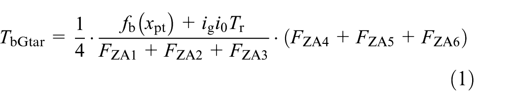
where,
According to the difference between the actual braking torque and the target braking torque, the pressure of the spring brake air chamber switches among three modes: pressurizing (braking torque decreases), holding pressure (braking torque remains), and decompression (braking torque increases). Since the pneumatic–electronic control system well oscillates if switched between pressurized and depressurized mode frequently, reasonable upper and lower threshold values are determined after several simulations, which are 100 Nm and −100 Nm, respectively, and the switching logic is as follows


where,
At last, determine the displacement of the mandrel of tractor brake valve, and the braking ends when the displacement is 0 mm.
The flow chart of control strategy is shown in Figure 9. This strategy is built based on SIMULINK/Stateflow and linked to AMESim and TruckSim, which is presented in Figure 10.

United simulation model of optimized system in SIMULINK.
The simulation is made on a downhill with 0.2 road adhesion coefficient of left side and 0.5 of right side, 15 the initial speed of braking is 30 km/h, the time step is 0.01 s. The result of original air brake system is shown in Figure 11. It can be seen that the braking torque of tractor rises in about 0.03 s, while braking torque of semitrailer starts to increase at about 0.23 s, which means that the brake lag is 0.2 s.
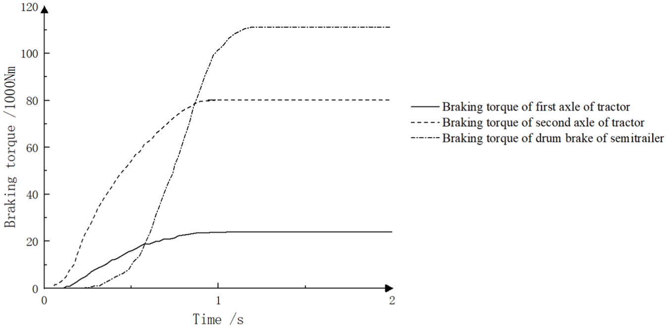
Brake lag of original air brake system.
The simulation of the optimized braking system of semitrailer is made under the same condition, and the result is shown in Figures 12–14.

e (Difference of actual and target braking torque).

Actual braking torque of drum brake of semitrailer.
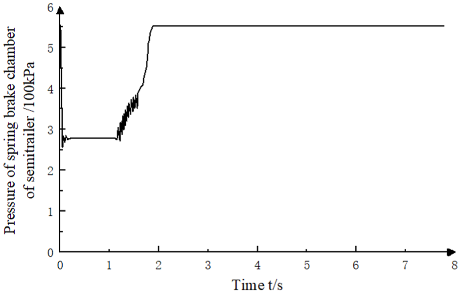
Pressure of spring brake cylinder of semitrailer.
At the beginning of braking, due to the slow response of the service brake chamber, the difference between the actual braking torque of the brake and the target braking torque is much less than −100 Nm, so the normally open valve closes, the normally closed valve opens, and the semitrailer spring brake cylinder begins to exhaust, with its pressure decreases within 0.04 s. Meanwhile, the semitrailer brake starts with braking torque increasing. Afterward, the pressure in spring brake cylinder decreases to 0.275 kPa within 0.03 s. Since the braking torque of the semitrailer brake increases rapidly, the absolute value of e decreases, and the actual braking torque approaches the target braking torque gradually. After 1.20 s, e has a fluctuation that lasts for 0.42 s in the vicinity of 0 Nm, which indicates that the actual braking torque of the semitrailer brake is basically equal to the target braking torque, and the pressure of the spring brake cylinder starts to rise with fluctuation. At 2.16 s, e is equal to 0 Nm, the pressure in spring brake cylinder is restored to 0.55 kPa, and the exhaust brake is released. In another word, the optimized scheme reduced the time required for the start of semitrailer to 0.04 s, which is a reduction of 83.6%, compared with the 0.23 s of original brake system. And the brake lag is reduced from 0.2 s to 0.01 s, which is a reduction of 95%, which means the tractor and semitrailer can start braking almost simultaneously.
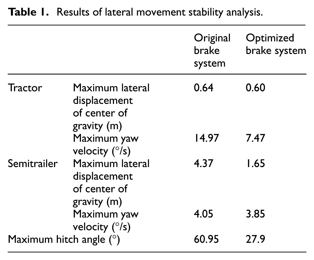
The lateral movement stability is also analyzed and the lateral movements of tractor and semitrailer are presented in Table 1 and Figures 15–17. It can be obtained that the maximum lateral displacement of center of gravity and maximum yaw velocity of tractor are 0.60 m and 14.97 °/s, respectively, and in the new system, they are 0.46 m and 8.38 °/s. For the semitrailer, the maximum lateral displacement of center of gravity and the maximum yaw velocity are 4.37 m and 4.05 °/s, respectively, and in the new system, they are 2.54 m and 3.85 °/s. The maximum hitch angle is 60.95° corresponding to 27.9° after optimization. The simulation results show that when the initial braking speed is 30 km/h, the improved scheme inhibits the lateral movement of the tractor-semitrailer obviously on the bisectional road, and reduced the brake lag by 0.19 s.
Results of lateral movement stability analysis.

Move track of center of gravity.
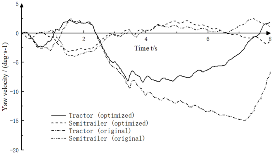
Yaw velocity.

Hitch angle.
Experimental verification of the improved air brake system
An experiment is designed to compare the brake lag before and after the air brake system being optimized to verify the effectiveness of this study. For the tractor-semitrailer, the performance of time lag is the difference in response time of brake chambers between the tractor and semitrailer. So air pressure sensors are installed on the brake chambers of both tractor and semitrailer. Due to limited test conditions, the experiment only tests for the brake and does not validate the control strategy. And once the brake pedal is pushed, the normally open solenoid valve and normally closed solenoid valve will get the signal to active.
The photo of experimental facility is presented in Figure 18.

Photograph of the experimental facility.
Figure 19 presents the changes in air pressure of service brake cylinders of both tractor and semitrailer, while Figure 20 shows the corresponding data of the optimized air brake system. It can be seen that, for the original system, after the pressure of the brake chamber of tractor rising 0.05 s. As a contrast, the optimized air brake system has an obvious better performance in brake lag. The pressure of the brake chamber of semitrailer rises even earlier than tractor. Figure 20 shows that the pressure of the brake chamber of semitrailer responds 0.05 s earlier than tractor. The main reason is that the brake of semitrailer of optimized air brake system is controlled by electric signal, which is much faster than pressure. The composite brake chamber responds almost at the time as the brake pedal being pushed. Besides, the pressure of service brake cylinder of semitrailer remains around 0.25 kPa at 0.11 s for about 0.05 s, then continuous climbing. It is because the air pressure of the spring brake cylinder is equal to the air pressure of the service brake cylinder after exhausting, and once the compressed air, from the storage reservoir, get in the service brake cylinder, the pressure goes up continuously.

Pressure change of service brake cylinders of tractor and semitrailer of original air brake system.

Pressure change of service brake cylinders of tractor and semitrailer of optimized air brake system.
It can be concluded that the optimized structure of air brake system gives the service brake cylinder of semitrailer a 0.1 s improvement of response time. Compared with the result of simulation, although there is a difference which is mainly caused by the model accuracy, the overall trend of change is the same, and the results of both simulation and experiment verify the effectiveness of the optimized structure of air brake system.
Conclusion
An optimized scheme of air brake system for tractor-semitrailer to improve braking stability by reducing brake lag is presented in this article. A normally open solenoid valve and a normally closed solenoid valve are added into air brake system to control the spring brake cylinder electronically to shorten the response time of semitrailer brakes. The improved air brake system model is built and simulated based on AMESim and SIMULINK, as well as the control strategy. The results show that compared with the original air brake system, the optimized system can reduce brake lag by 0.19 s and inhibit the lateral movement of the tractor-semitrailer obviously. The experiment also shows that the brake of semitrailer of the optimized air brake system responds earlier than the tractor, which means the brake lag has been improved effectively. And the future research will be devoted to the interaction with the ABS system, vehicle air consumption, and other aspects, and advanced experiment will be made on real-world tractor-semitrailer.
Footnotes
Acknowledgements
Zhecheng Jing likes to show his deepest gratitude to his supervisor, Professor Ren He, who has provided him with valuable guidance in finishing this work.
Handling Editor: James Baldwin
Declaration of conflicting interests
The author(s) declared no potential conflicts of interest with respect to the research, authorship, and/or publication of this article.
Funding
The author(s) received no financial support for the research, authorship, and/or publication of this article.