
Abstract
Researchers are continuously developing various energy-saving technologies to enhance the internal combustion engine efficiency. Among them, continuous variable valve timing and variable valve lift system is one potential technology. To achieve this ability, a new type of electric valve, known as magnetorheological valve train, was introduced, which is based on the magnetorheological fluid’s active behavior. In this study, gasoline engine models are established for dynamic simulations of an engine with the magnetorheological valve train. Volumetric efficiency and performance of the engine with different magnetorheological valve train valve lifts and valve timings at engine speeds between 2000 and 6000 r/min are also analyzed. Simulation results show that, at low engine speeds, the lift of the valve has little effect on the engine performance. However, under high and medium engine speeds, the lift of the valve significantly affects the performance; the smaller the valve lift, the smaller the volumetric efficiency. Likewise, an adjustment of valve opening angle timing to reduce the valve overlap angle effectively increased the engine volumetric efficiency at low engine speeds.
Keywords
Introduction
With the development of science and technology, the production of mobile vehicles in the world has risen sharply. However, while people enjoy the speed and convenience provided by the mobile vehicles, these vehicles also create environmental problems such as huge energy consumption and air pollution. Therefore, fuel efficiency and energy saving issue has become a major trend in automotive engineering today.
In response to the present environmental and energy problems, several major environmental organizations in the world have publicized several relevant regulations on automobile exhaust emission for the purpose of environmental protection. The Euro regulations about vehicular exhaust emission regulate nitrogen oxides (NOxs), hydrocarbons (HCs), carbon monoxide (CO), and suspended particulates (PM) for all types of vehicles. Most automobile industries are developing solutions with electric vehicles, fuel cell vehicles, and other vehicles in compliance with Euro regulations and energy conservation. However, those vehicles are not yet extensively used due to the limitations of insufficient cruising mileage and lengthy charging time. Therefore, the technology of high-efficiency engine in vehicle research and development is even more important.
In various high-efficiency engine technologies, electric valves can be regarded as one of the most promising technologies. A traditional four-stroke engine mostly uses a camshaft to push a rocker arm, thereby compressing the valve spring to open the air valve. Therefore, the opening and closing of valve profile is fixed, which leads to unsatisfactory engine performance at high or low engine speeds.
Many automobile industries develop variable valve actuation (VVA) technologies such as variable valve timing (VVT) and variable valve lift (VVL) to improve engine combustion efficiency. VVT is one of the reliable methods to achieve higher engine performance in all speeds. Osorio and Rivera-Alvarez 1 compared a continuous variable valve timing (CVVT)-installed engine with a conventional engine. It shows that during part loads, the CVVT engine obtained 4.1% fuel economy increment. Alternately, VVL is one more type of valve actuation method, in which the maximum valve lift extent varies according to the engine’s dynamic condition. It increases the engine performance at low load conditions. Wang et al. 2 investigated this low lift profiles with swirl and tumble flow characteristics and concluded that the lift variations give notable effect on combustion.
The common advantage of these two techniques is reduction of pumping loss at engine part load condition. Li et al. 3 compared VVL and VVT with the support of engine bench test and numerical simulations and concluded that VVL has more advantage in the reduction of backpressure aspect. However, VVT overcomes another major problem of spark-ignition (SI) engine, that is, valve overlap period. Khudhur et al. 4 conducted experimental investigation to understand the overlap-period variation effect on engine performance and found more than 12% improvement in the volumetric efficiency.
Kutlar et al. 5 discussed in their paper about the VVA requirement at part load and low speed conditions. Also, in the past, Shiao and Dat 6 tested VVT and cylinder deactivation (CDA) strategies to improve SI engine efficiency, and their simulations show a growth of more than 30% at low engine load and 11.7% at medium engine load. Using the high degree of freedom of variable valve technology, VVT and VVL have quite the potential for the development of high-efficiency engines. To achieve these active valve actuations, the existing electric valve technologies are as follows: electromagnetic valve (EMV), hydraulic valve train system (HVS), electromechanical valve drive (EMVD), and electrosolenoid valve (ESV).
Gaeta et al. 7 proposed an electromagnetic mechanical valve actuator (EMVA). The EMV consists of two groups of upper and lower springs, a core, and an armature. The upper or lower coil is energized to generate a magnetic force to attract the armature and valve, so that VVT and VVL can be achieved. Since the medium between the armature and the electromagnetic coil is air with low magnetic permeability, the magnetic force that can be generated by the electromagnet is limited. Therefore, the armature can only receive a large magnetic force when it approaches the electromagnet. In order to enable the right valve opening and closing, the solenoid of EMV must be powered on and off in a very short time. However, the coil is susceptible to hysteresis during quick energizing and de-energizing, which prevents the reliable release of the armature and causes the armature to fail. Under such a situation, the valve cannot open and close properly and consequently affects engine operation. In addition, when the coil is not energized, the armature is in its neutral central position and the valve is in half-open state, making the valve easily crash with the head of the cylinder piston.
An innovative electromechanical fully variable valve train (EMFVVS) is suggested in Wong and Mok. 8 When cam lobes compress tappets and tappet springs, the hydraulic pressure in the master cylinder changes. The electrical control unit calculates the engine load and speed, then calculates the appropriate valve lift and timing, and then sends the signal to the proportional pressure relief valve.
Another fully flexible valve actuation (FFVA) system was also proposed. 9 The control system controls the piston displacement inside the servo valve to change the direction of the fluid flow, so as to provide valve timing and lift effects.
A MultiAir system was presented by Fiat. 10 The system replaces the traditional intake valve mechanism with a set of solenoid valves. It uses a cam lobe to push the fluid in the hydraulic actuator into the hydraulic chamber and uses an EMV to control the amount of the fluid, to achieve variable timing and lift. Another VVA system provides functions of variable time and lift by controlling the pressure change and actuation time of an actuation valve and lift valve. 11 However, the disadvantage of the system is the need for extra plug-in pipeline and booster equipment for the operation.
An EMVD and variable valve event and lift (VVEL) system 12 were developed by Nissan Motor. By controlling a DC motor to move the ball screw nut over the ball screw shaft, the drive mechanism on the rock arm of the gas valve is actuated to allow the valve lift to be continuously variable effected.
Moreover, BMW developed the VVT technology of the electromagnetic control valve (ESV) VANOS. 13 The device is furnished with a set of actuators to change the cam phase at the tail end of the cam. When the engine is at a low speed, the gas valve is delayed by changing the cam phase, thus the engine can be more stable. When the engine accelerates, it produces a more powerful torque and high-speed driving, but also has delayed start to create a greater momentum.
All of these systems have their individual advantages, but face common problems like high response time, more power consumption, complex design, high maintenance, and less flexibility. In this context, magnetorheological (MR) fluid is one of the promising materials for MR-type actuation devices. The viscosity of MR fluid changes with magnetic field intensity. Using this dynamic property, alternative devices to conventional actuators can be designed. Ashour et al. 14 explained about the MR fluids’ properties and applications and also introduced a MR valve. It works based on MR fluid flow-resistance mode, in which the flow of MR throttle valve can be changed by adjusting current intensity in excitation coils. Using this technique, a MR throttle valve had been designed and analyzed. 15
By considering all these systems, a novel engine valve with MR valve technology, which can overcome the problems in conventional engine valve actuators, is introduced first. This study is to understand the performance of an engine with different valve actuations at different speeds using this novel device’s valve train flexibility.
Characteristics of the new MR electric valve
An innovative variable valve applying MR technology, which offers variable timing and lift together, was developed in the author’s laboratory, and the real prototype is shown in Figure 1. This electric valve applies an electromagnet to control the flow rate of a smart fluid, MR fluid, and then control the timings of valve open and close as well as the lift of valve. The structure and operation of this magnetorheological variable valve train (MRVVT) was initially introduced in Shiao and Cheng. 16 There is a brief introduction about this MR valve before mentioning its applications in this paper.

The new magnetorheological electric valve.
As shown in Figure 2, the electric valve MRVVT is composed of three major parts: the actuating zone, the magnetic zone, and the buffer zone. According to the percentage of valve lift, there are three working modes for the MR electric valve: fully open mode, fully closed mode, and adjustable lift mode.

Structure of the magnetorheological electric valve. 16
In fully open mode, as shown in Figure 3(a), the coil is not energized. So, there is no activated magnetic field in the magnetic zone, and no corresponding viscous resistance is produced for the MR fluid flowing through the magnetic zone. When the cam pushes down the upper piston, the MR fluid flows evenly to the actuating zone and buffer zone. Thus, the lower piston pushes the valve to its fully open position to have maximum valve lift in this mode.

Three modes of MRVVT: (a) fully open mode, (b) fully closed mode, and (c) adjustable lift mode.
In the fully closed mode, as shown in Figure 3(b), a maximum current is applied to the coils to generate strong magnetic field in the magnetic zone. Then, there is a very high viscous resistance to the MR fluid in this zone. It prevents the MR fluid from flowing through the MR zone to the actuating zone and forces all fluid flowing to the buffer zone. Therefore, in this mode, the lower piston stops in its top position and the valve lift is zero.
The MR fluid in the magnetic zone changes its shear force due to the particle chaining effect under the influence of the magnetic field passing through it. This shear force can be controlled by adjusting the applied current. When the cam presses the upper piston down, the resistance in the magnetic zone partially limits the fluid flow rate and more fluid will flow to the buffer zone. Only a small quantity of fluid is pressed down to the actuating zone to push down the lower piston and the corresponding valve. Thus, the valve lift can be controlled by adjusting the applied current to the coils. As shown in Figure 3(c), taking the half-open valve as an example, when a certain amount of current is applied, the pressure in the magnetic zone is greater than the pressure in the buffer zone, and the flow in the magnetic zone will be half of that in the buffer zone to reach the half-open state.
Engine dynamics simulation
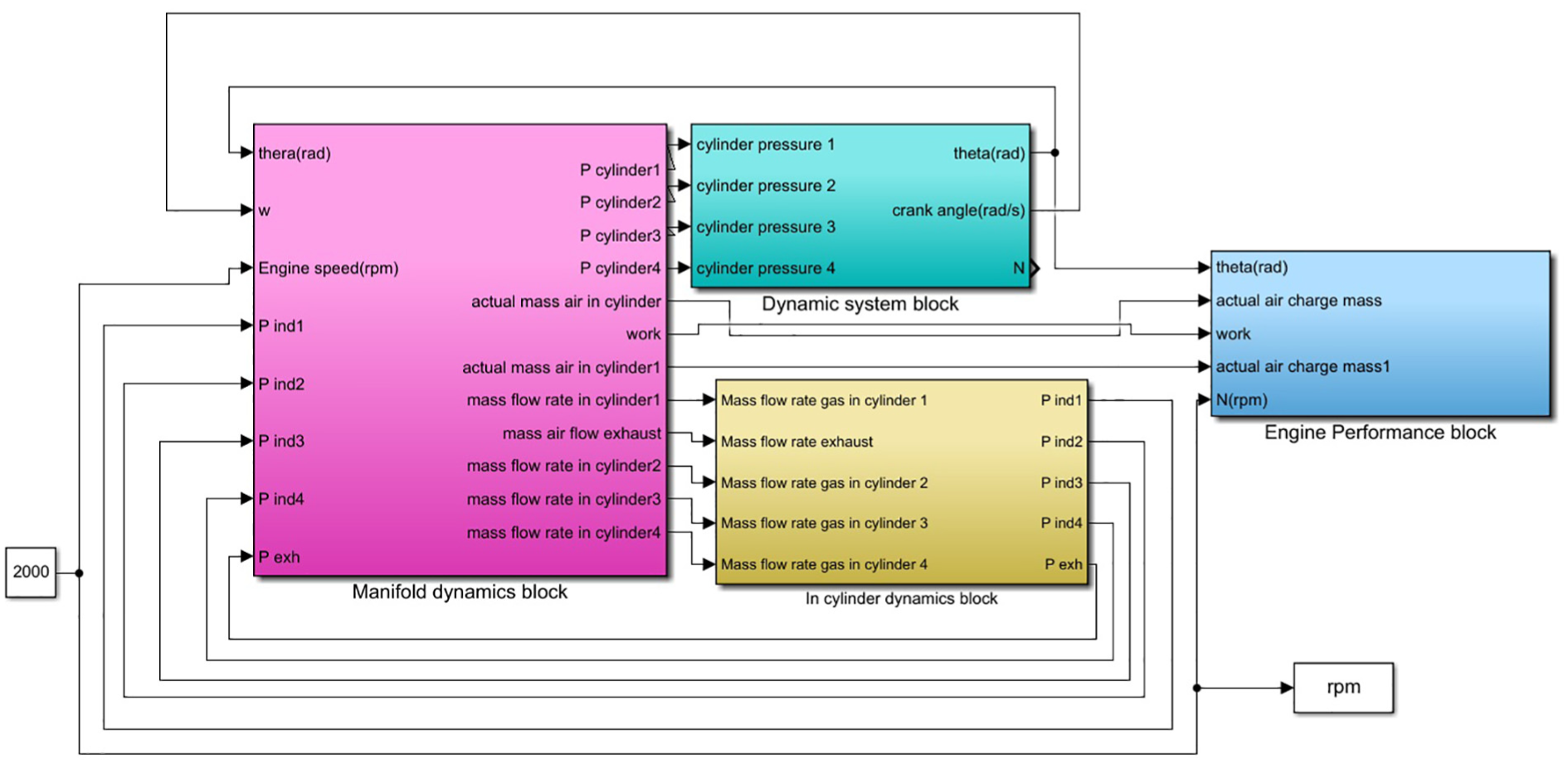
The engine dynamic simulation module used in this study was based on the non-throttled engine model in Shiao and Dat 6 and modified the cam profile and some engine parameters. The engine dynamic module specifications are shown in Table 1. As shown in Figure 4, this model was established in MATLAB Simulink with four function blocks: manifold dynamics module, in-cylinder dynamics module, dynamic system module, and an engine performance module. First, the manifold dynamics block is prepared by filling an empty model to calculate the mass flow rates in the intake and exhaust manifolds. Besides, required valve timing and lift curves were introduced in this manifold dynamics block. Second, the in-cylinder dynamics block is organized with Weibe function of combustion to compute the pressure and the work done in cylinders. Next, the dynamic system block is to identify the crank angle dynamically. Finally, the engine performance block is to evaluate the engine performance parameters with Barnes-Moss experimental correlation for friction and heat transfer equations. Thus, the engine power, torque, fuel efficiency, and volumetric efficiency can be calculated. All these blocks are interlinked to form a required engine model.
Specifications of engine dynamic module.

BTDC: before top dead center; ATDC: after top dead center; BBDC: before bottom dead center.
Engine dynamic module.
The main property parameter to represent engine output performance is its mean effective pressure


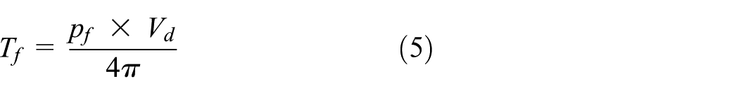
The actual torque output of the engine must overcome the generated friction torque

where


Specific fuel consumption refers to the fuel required to produce a unit horsepower per hour, which is calculated as

The volumetric efficiency is defined as

Results and discussions
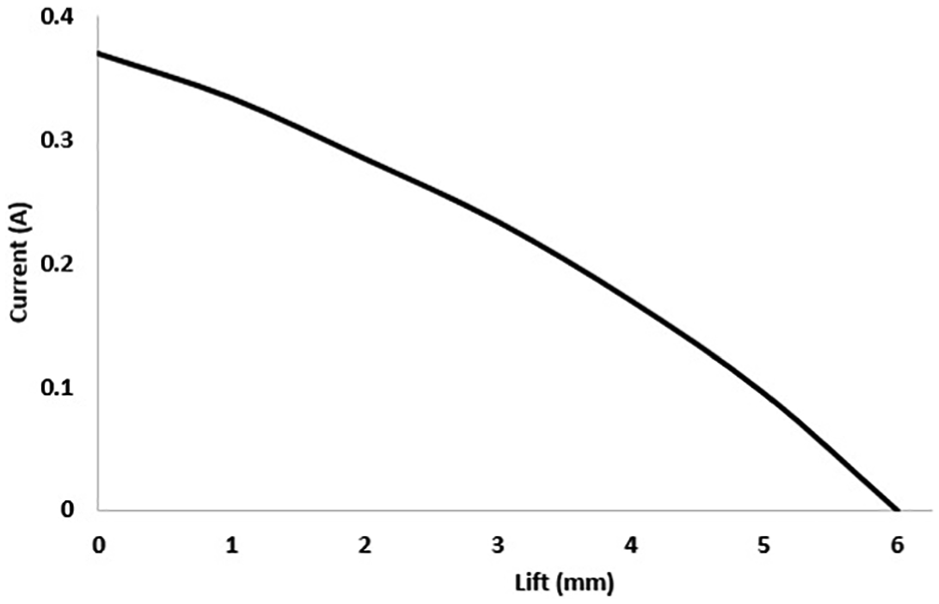
The camshaft used in the MRVVT is shown in Figure 5. To connect the MRVVT property and engine model, cam lift and resistance force of MR valve for different actuated currents must be described first. The applied current level can be used to control the magnetic resistance in the magnetic zone, as shown in Figure 6. The resistance increases as the current increases, and it will reach a saturated value at large current (i.e. 2 A). Thus, the fluid resistance will affect the pressure difference between the buffer zone and the magnetic zone to determine the individual mass flow rate for the two zones. Figure 7 shows the relationship between valve lift and applied coil current. Under an applied current of 0.38 A, the pushing force from the cam is completely absorbed by the buffer zone such that the valve has no lift. The valve has maximum lift (6 mm) if no current is applied to the coils.

The camshaft.

Relationship between MR fluid resistance and coil current. 16
Relationship between valve lift and coil current.
VVL dynamic simulation
The dynamic simulation can be divided into two parts: VVL and VVT. The simulation of valve lift is changing the amount of valve lift to explore the impact to engine performance. In the simulation of VVT, only simulation of early intake valve open is conducted, because this MRVVT cannot have function of late valve close due to its mechanical constraints.
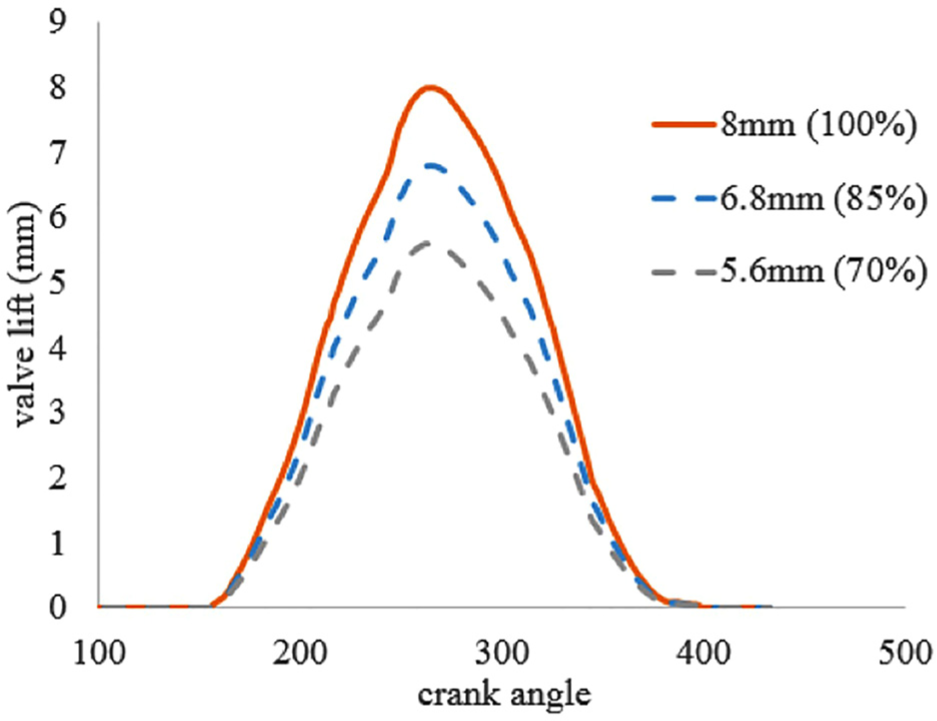
The engine dynamic module has a preset 8-mm valve lift, and the real MR electric valve has only 6-mm maximum valve lift. Therefore, in the simulation, the 6-mm lift profile must be multiplied by 1.333 to achieve the preset 8-mm valve lift in the model. Also, due to limitations of the engine module, the minimum limit of valve lift at high engine speeds is about 70% (5.6 mm). If the valve lift is below 70% (5.6 mm) at 6000 r/min, the engine module will stall. Therefore, this article mainly simulates the MR electric valve with full-open (8 mm), 85% open (6.8 mm), and 70% open (5.6 mm) modes (Figure 8) at fixed valve timings and at engine speeds from 2000 to 6000 r/min. The valve timing is shown in Table 2. Engine load variation is not considered as a parameter in this research. As valve opening and closing take place during intake stroke, the pressure variation there due to engine load changes is very small and negligible. So, the load change in required resistance force at active block to control the valve can be negligible.
Valve lifts for simulation.
Valve timing.
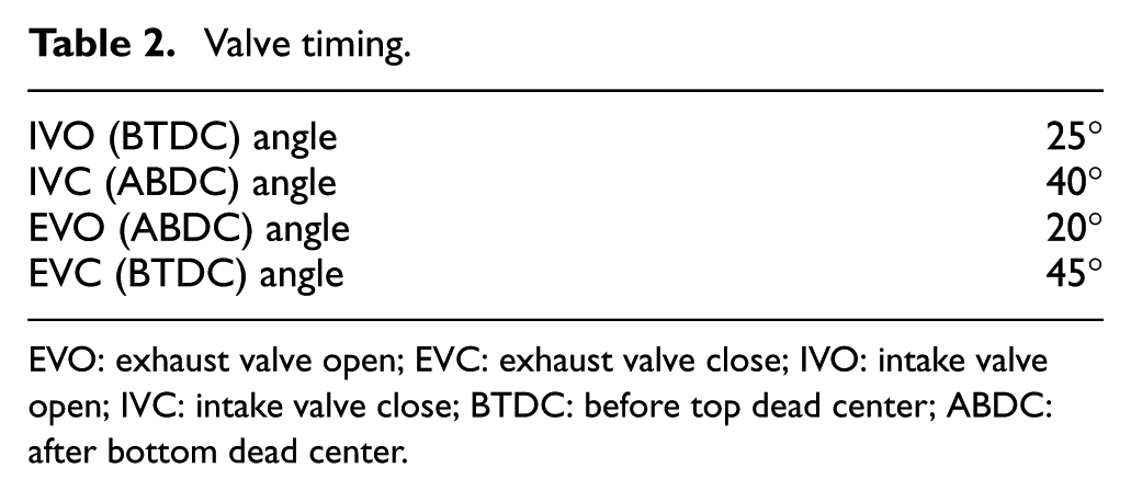
EVO: exhaust valve open; EVC: exhaust valve close; IVO: intake valve open; IVC: intake valve close; BTDC: before top dead center; ABDC: after bottom dead center.
Figure 9 shows the volumetric efficiency of the valve lift at different engine speeds. It shows that the change of valve lift at low speeds has little effect on the volumetric efficiency. However, after 4000 r/min, the smaller the valve opens, the smaller the volumetric efficiency. Reason for this is that the cylinder intake period is already small at high speeds, and the small valve lift results in small intake mixture. Therefore, at high-speed conditions, higher valve lift operation is needed to get the required volume of intake. With this variation, 10%–12% volumetric efficiency improvement can be achieved as shown in Figure 9.

Volumetric efficiency of different valve lift at each speed.
Engine horsepower curves for different valve lifts at various speeds are shown in Figure 10. Horsepower is not significantly affected by valve lift at low engine speeds (2000 and 3000 r/min). However, there is a large power difference after 3000 r/min, that is, horsepower improved 10% at 3000 r/min and 30% at 5000 r/min. It is because under the condition of constant valve timing, increasing the valve lift amount can increase the air flow rate to cylinder to make the air intake more adequate. There is a power peak at around 5000 r/min in Figure 10 and torque peak at around at around 3000 r/min in Figure 11. Generally, engine friction increases dramatically at high engine speeds, which results in torque decreasing and power decreasing at high engine speeds. Thus, the engine power decreases after 5000 r/min in Figure 10 and engine torque decreases after 3000 r/min. It is very clear to see the trend of high valve lift advantage at high speeds.
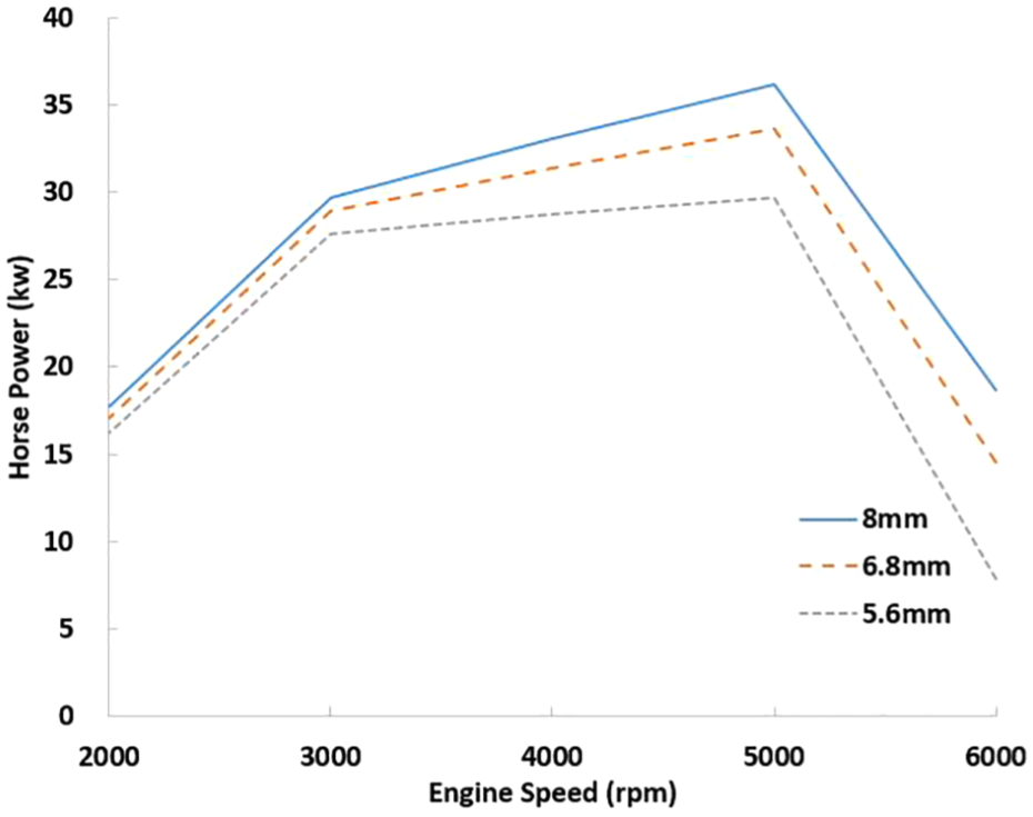
Engine horsepower at various speeds for different valve lifts.

Engine torque for different valve lifts at various speeds.
Figure 12 shows the brake-specific fuel consumption (BSFC) at each speed with valve opening 8 mm. From 2000 to 5000 r/min, the fuel consumption at 3000 r/min is the least. In addition, engine torque at different rotational speeds of the valve lift in Figure 11 shows that the engine has maximum torque boost at 3000 r/min. Thus, the engine at 3000 r/min has the highest fuel efficiency. The torque decreasing after 3000 r/min is also because of the high engine friction torque at high engine speeds.

BSFC for 8-mm lift at different speeds.
The jump change of BSFC at 0.2 s in Figure 12 is a transient period error in engine simulation from initial state into steady state, which is not considered in the analysis. Simulation results achieved steady state after 1 s, and only these results are taken for comparison.
VVT dynamic simulation
The research results in Kutlar et al. 5 show that the effects of exhaust valve open (EVO) and exhaust valve close (EVC) angles on engine volume efficiency are not significant at any speed. Therefore, the dynamic simulation of variable timing in this section follows the original exhaust timing in the engine module.
In the simulation, the intake valve timings were set as the values in Table 3. The intake valve open 5° early (before top dead center (BTDC)) at low engine speeds; intake valve open 15° early (BTDC) at medium speeds; and intake valve open 25° early (BTDC) at high speeds. Since this MR electric valve cannot offer the function of late valve close, the timing of the exhaust late is set at 40° after bottom dead center (ABDC).
Valve timing optimization.
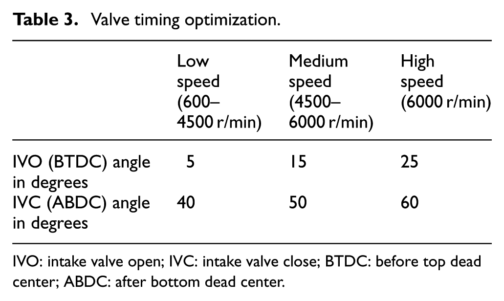
IVO: intake valve open; IVC: intake valve close; BTDC: before top dead center; ABDC: after bottom dead center.
According to the experimental results of variable timing for the MR electric valve (Figure 13), the effect of variable valve time can be achieved if maximum current is applied at 110° of cam angle and zero current is applied at 130° of cam angle. Figure 13 shows the lifts of cam lobe, intake valve, and valve in buffer zone. Figure 14 shows the relationship between the valve lift and angle of current off. The timing parameters for the simulation of VVT are summarized in Table 4.

Displacement response with closing current at cam angle 130°.

Current closing angle and valve lift.
Dynamic valve timing simulation.

EVO: exhaust valve open; EVC: exhaust valve close; IVO: intake valve open; IVC: intake valve close; BTDC: before top dead center; ABDC: after bottom dead center; ATDC: after top dead center; BBDC: before bottom dead center.
The volumetric efficiency of the variable timing and the normal timing at each rotational speed is shown in Figure 15. The efficiency is higher at variable timing than at the normal timing at low rotational speeds, because the valve overlap period of the normal timing valve is larger than that of the electric valve timing. In addition, gas inertia is small at lower speeds, which causes fresh mixture to be expelled with the exhaust gas. Thus, there is no sufficient fresh mixture into the cylinder to result in the significant drop of engine efficiency.

The volumetric efficiency for the normal and magnetorheological electric valve timings.
As shown in Figure 16, the engine with MRVVT has the best volumetric efficiency at 3000 r/min (i.e. 5% to 6% improvement) and also generates the maximum torque (i.e. 12% higher torque than a normal engine). At high speeds, due to the high gas inertia, the late intake valve opening angle does not cause obvious difference in engine volumetric efficiency and torque. With this MRVVT, the required highest torque is achieved at all speeds. This torque value is higher than normal engine at low speeds. It is because the late valve opening makes high pressure difference, which gives high mass flow rate during intake stroke.

The torque for the normal and magnetorheological electric valve timings.
As shown in Figures 17–19, applying the VVT control and having 20° late intake valve opening at 2000 and 3000 r/min, the problem of excessive valve overlap angle can be effectively improved. Thus, the engine in this speed section is not only more fuel efficient but also has increased engine horsepower. However, at higher speeds, due to late intake valve opening angle resulting in little effect to volumetric efficiency, the engine horsepower increase is not significant.

BSFC at 2000 r/min.

BSFC at 3000 r/min.

Horsepower for different speeds for variable valve timing and normal timing.
From Figure 17, it is clear that the late valve opening (i.e. 5° BTDC) gives better performance than early valve opening, that is, 25° BTDC. This 5% BSFC improvement is because of less valve overlap angle, less fuel trapped into exhaust, and less fuel consumption. Similar phenomenon occurred at 3000 r/min, as shown in Figure 18, but the late valve opening advantage was quantitatively 30% less than 2000-r/min condition. This is because, at higher speeds, the time available for fuel trap is less.
There is also a horsepower drop after 5000 r/min, as shown in Figure 19. This power drop results from the large engine friction torque at high engine speeds. Thus, the engine torque decreases, and consequently the engine power decreases. The results show that the performance of the engine with MRVVT and without MRVVT is similar at higher speeds. However, at low speeds, VVT produces higher torque compared to a normal engine. This is because of fuel not getting trapped into the exhaust and because of the optimal intake charge availability in the cylinder.
Integrated variable timing and lift of the dynamic simulation
The MR electric valve can have continuous variable lift and timing by controlling the energized time and level of coil current. By adjusting the level of applied current to the coil, the effect of VVL can be achieved (Figure 20). By control valve timing, a maximum current is held until the desired timing angle to achieve the effect of VVT (Figure 21).

Different levels of variable lift.

Valve lift with variable timing.
The simulation of combination of variable timing and variable lift is shown in Figure 22. In the figure, with a 20° late angle, a maximum current is applied to the field coil when the cam rotates to 50°. The large viscous shear force resulting from the strong magnetic field prevents the valve from pushing down to open. When the cam rotates 70°, the applied current is decreased to reduce the viscous shear force. Then, the valve is pushed down. The relationship between the applied currents and different lifts can be obtained from Figure 7. Table 5 shows the simulation parameters. The speed range of this dynamic simulation was from 2000 to 5000 r/min.
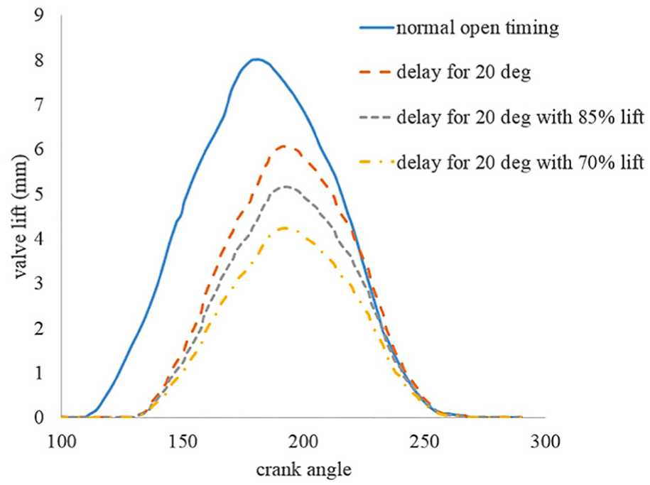
Combination of variable lift and variable timing.
Simulation parameters for combination of variable valve timing and lift.

BTDC: before top dead center.
As shown in Figures 23 and 24, the volumetric efficiency and torque are reduced by the valve lift reduction. The smaller the valve opening, the smaller the volumetric efficiency and torque. As shown in Figure 25, the engine output power is significantly affected by the valve lift, especially at speeds more than 3000 r/min.

Volumetric efficiency for variable lift and timing.

Torque for variable lift and timing.
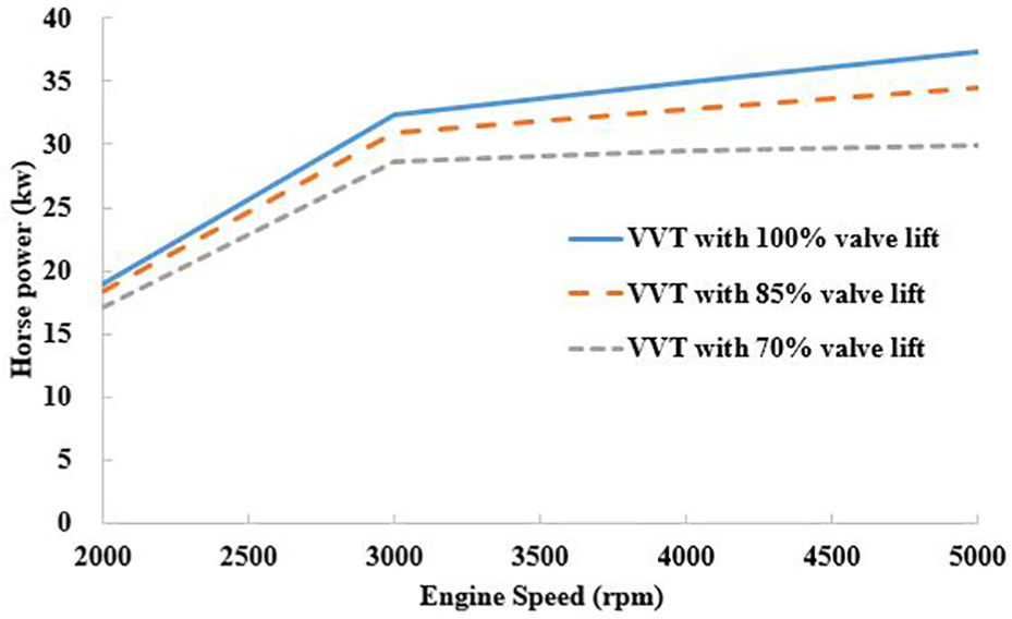
Horsepower for variable lift and timing.
Conclusion
In this article, the dynamic output performance of an engine with MR electric valve for different engine speeds is simulated. Because the proposed MR electric valve has a high degree of freedom for change of valve lift and valve timing, an engine with this electric valve can obtain higher engine torque and better engine efficiency. This research also shows the way to get VVL, VVT, and combination of VVL and VVT. At different engine speeds, the appropriate use of variable lift and timing can make the engine more efficient. Quantitatively, during lower engine speeds, because of this variation in the valve timing, 8%–10% improvement of volumetric efficiency, 5%–7% increase in horsepower, and up to 9% improvement in BSFC can be attained. Moreover, by introducing high lifts at high speeds, the required horsepower can be attained and volumetric efficiency can be improved up to 8%. The engine model used for this simulation does not consider the turbulence effect. If that is also considered, these quantities would be even better. Still, this study identified the advantage of valve actuation flexibility of the proposed MRVVT device in the engine.
Footnotes
Handling Editor: Jan Awrejcewicz
Declaration of conflicting interests
The author(s) declared no potential conflicts of interest with respect to the research, authorship, and/or publication of this article.
Funding
The author(s) disclosed receipt of the following financial support for the research, authorship, and/or publication of this article: The research was financially supported by Ministry of Science and Technology, Taiwan (project number: MOST 104-2221-E-027-083).