
Abstract
In this study, the dynamic responses of a double-stage geared rotor-bearing system with translational motion due to the effects of rotating shaft deformation were examined, which was lacking in past research. Residual shaft bow has been neglected in most geared rotor-bearing system models. In this study, the dynamic response of a double-stage geared rotor-bearing system whose gear set underwent translational motion was examined when the shaft was deformed (residual shaft bow). The proposed model considers contact ratio and pressure angle of gear pair as time-dependent variables, whereas in other models, they are constants. A finite element model of a double-stage geared rotor-bearing system with residual shaft bow was developed, and equations of motion were obtained by applying the Lagrange’s equation. System equations of motion are solved by Runge–Kutta numerical method. The dynamic response was investigated, including lateral response, contact ratio and pressure angle of gear pair with different residual shaft bow magnitudes and gear positions. The results show that residual shaft bow raises the amplitudes of lateral displacement, contact ratio and phase angle of gear pairs in the system. This study demonstrated that the residual shaft bow effect is too considerable to ignore when it becomes sufficiently large.
Keywords
Introduction
The gear is one of the basic components of the transmission. The geared rotor-bearing system is one of the main mechanisms of modern power transmission. Given the increasing demand for high-speed, accurate transportation, research on geared rotor dynamics is highly necessary. Much research has been conducted on the dynamic characteristics of rotor-bearing systems, indicating that system parameters significantly influence these characteristics. Such parameters include system geometry, bearing coefficients, rigid disk inert properties, mass distribution, and rotational component stiffness. Many methods exist for determining natural frequencies, critical speeds, mode shapes, and steady-state response due to rotor-bearing system unbalance. For example, Gunter 1 evaluated the effect of damped, linear, flexibly mounted rolling element bearings on dynamic rotor imbalance response. Lund 2 presented a scheme for computing the percentage of critical speed change caused by a corresponding change in any rotor model element. Buccuiarell 3 studied unbalance response due to rotating shaft instability and clarified how the internal forces are coupled to the whirl motion to create instability. Awrejcewicz and Pyryev 4 investigated nonlinear problem of the thermoelastic contact of a rotating shaft with a rigid bush fixed to the base springs. Awrejcewicz and Pyryev5,6 developed a new one-dimensional thermoelastic frictional pair contact model of a shaft-bush system and developed inertial contact of a braking pad and a rotating inertial shaft. Awrejcewicz and Kudra 7 described the real piston-connecting rod-crankshaft system.
The finite element method (FEM), a specific numerical calculation procedure that provides more accurate modeling, is used to analyze rotor-bearing systems. Ruhl and Booker 8 described a distributed element model of a general turbo rotor-bearing system in which distributed inertia and elasticity were consistently represented. Nelson and McVaugh 9 developed a finite element model of the rotor-bearing system that included the effects of rotary inertia, gyroscopic moment, and axial load. Nelson 10 studied the influences of shear morph and moment of inertia on rotor-bearing systems by means of Timoshenko beam theory and the FEM. Ozguven and Ozkan 11 described dynamic modeling of the rotor-bearing systems, including moment of inertia, gyroscopic effect, axial load, internal viscous and hysteretic damping, and lateral shear deformation. Chen and Ku 12 discussed the dynamic stability of the cantilevered axle system formulated using the shape function obtained by Timoshenko beam theory. The effects of translational and moment of inertia, gyroscopic moment, bending, and shear morph were included in their mathematical model. Shiau and Hwang 13 developed a generalized polynomial expansion method for determining critical speeds and modes and the imbalance response of rotor-bearing systems.
Gears are widely used in industrial applications. When a drive system incorporates gear transmission units, lateral and torsional modes are coupled. Determining the lateral and torsional frequencies of rotor systems is essential when designing geared rotor-bearing systems. Most research has emphasized the analysis of lateral motion. Iida et al. 14 considered a simple geared system including torsional and flexural vibration coupling and calculated the response due to mass unbalance and eccentricity in the gears. Neriya et al. 15 extended the model of Iida et al. 14 by developing a single geared shaft system, including the flexibility of the matting teeth and both the drive and driven shafts in their analysis. They also investigated the forced vibration response due to mass gear unbalance.
Several studies on gear dynamics have employed FEM. Kahraman et al. 16 developed a finite element model of a geared rotor system supported using flexible bearings. The model included the rotary inertia of shaft elements, axial loading on shafts, flexibility and damping of bearings, material damping of shafts, and the stiffness and damping of gear mesh. However, their model did not consider the effect of the gear pair pressure angle. Shiau et al. 17 analyzed the coupled bending and torsional vibrations of geared rotors as well as the effect of axial torque on bending vibrations. Rao et al. 18 employed a finite element model to determine the coupled bending–torsional natural frequencies and mode shapes of a geared rotor-bearing system. Shiau et al. 19 described the dynamic behavior of geared rotor systems supported by squeeze film dampers in which coupled bending–torsional vibrations occurred. By considering unbalance forces and gravity, they demonstrated that geared rotors exhibit chaotic behavior due to the nonlinearity of damper forces. Choi and Mau 20 employed a transfer matrix model to determine the coupled bending–torsional natural frequencies and mode shapes of a geared rotor-bearing system. Steady-state responses due to excitation of mass unbalance, geometric eccentricity, and gear mesh transmission error were also obtained.
Dynamic models combining gears with flexible shafts and bearings have been proposed in many studies. However, the models in the literature vary in complexity, and most do not include gear nonlinearities and time-varying properties in the simulation. Kahraman and Singh21,22 discussed the nonlinear frequency response characteristics of a spur gear pair with backlash for both external and internal excitation, and extended their analysis to include sinusoidal or periodic gear mesh stiffness. Gao et al. 23 developed a finite element formulation to describe the nonlinear contact impact behavior of bevel gears. Baguet and Jacquenot 24 analyzed the interaction between gears, shafts, hydrodynamic journal bearings, and geared drives, including time-varying properties and nonlinearities of gear mesh stiffness and bearings. Kim et al. 25 analyzed the dynamic response of spur gears by considering the pressure angle and contact ratio as time-dependent variables, as well as gear set translational motion due to bearing deformation. Zhang et al. 26 developed a general three-dimensional dynamic model of helical gear pairs with geometric eccentricity. The gear mesh and bearing flexibility is included in the model as well. Wang et al. 27 developed an improved time-varying mesh stiffness (TVMS) model of a helical gear pair, in which the total mesh stiffness contains the axial tooth bending stiffness, axial tooth torsional stiffness, and axial gear foundation stiffness.
In practice, shafts deform after a certain length of service time. The residual shaft bow effect is a common fault in large rotating machinery and can lead to serious accidents. Residual shaft bow can be suppressed through design improvements based on the understanding of system characteristics. Nicholas et al. 28 investigated the residual shaft bow effect on the unbalance response of a single mass flexible rotor. Shiau and Lee 29 examined the dynamic response of a simply supported rotor under the effect of disk skew, unbalanced mass, and residual shaft bow. Song et al. 30 described the influence of residual shaft bow on rotor longitudinal responses through a simulation experiment. Chen and Kuo 31 developed a new dynamic model for the geared rotor-bearing system which is considering translational motion and residual shaft bow. The main aim of this study extended the model of Chen 31 by developing the dynamic characteristics of a double-stage geared rotor-bearing system with translational motion due to shaft deformation under the residual shaft bow effect. The gear lateral responses, pressure angle, and contact ratio were investigated with regard to the shaft deformation effect.
System modeling
The configuration of a double-stage geared rotor-bearing system is shown in Figure 1. The three uniform flexible shafts are of lengths


Configuration of a double-stage geared rotor-bearing system.

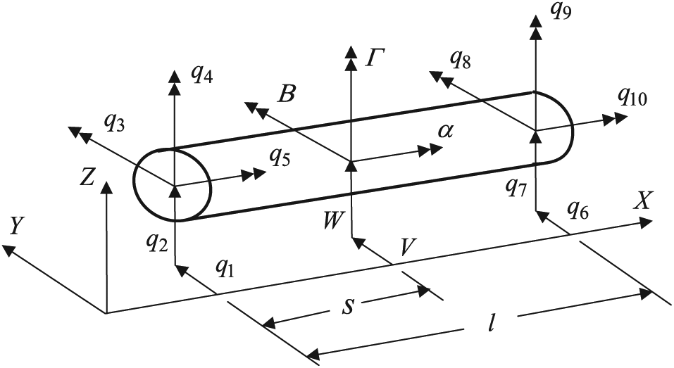
Typical rotor configuration and coordinates.
Shaft
For rotating shafts, which are modeled as Timoshenko beams, two-noded elements are used for the finite element formulation, as shown in Figure 3. Five degrees of freedom (


where A is the cross-sectional area;
Shaft element and the coordinate system.
The equation of motion of the finite shaft element can be derived by substituting kinetic energy equation (2) and strain energy equation (3) into Lagrange’s equation

where
Gear and spur gear mesh
In this study, the disk was a rigid body with five degrees of freedom, namely two lateral displacements,

where

where
Figure 4 shows the configuration and generalized coordinates for the pair of gears mounted on the shafts shown in Figure 1. The motion of the gear set can be defined using 10 generalized coordinates, which are identical to the node coordinates of the two shafts on which the gears are mounted. The dashed and solid circles represent the gear pair before and after motion, respectively.

where


Configuration and generalized coordinates for gear pair.
In Figure 5, the gear pair is modeled as the equivalent stiffness

where


Gear mesh model of the gear pair.
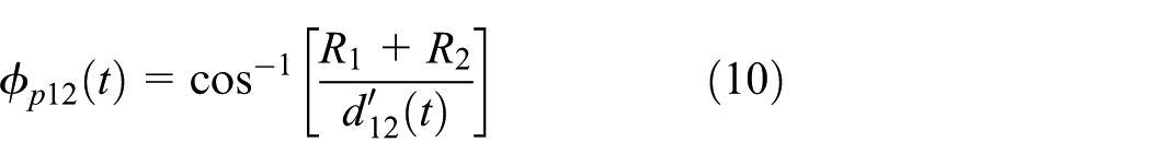
The contact ratio of the gear pair is represented as follows

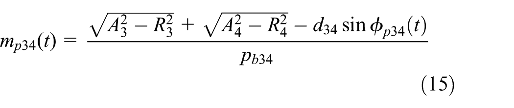
where


whereby the gear mesh force along the pressure line could be expressed as follows


The corresponding equation of motion for the gear pair can thus be obtained, as follows

where
Bearing
In this study, the six bearing supports assumed to be isotropic. Springs and dampers are used to model the bearing supports. Ignoring the effects of slopes and bending moments, the potential energy and dissipation function of the ith bearing support can be expressed, respectively, as follows


By using the Lagrange’s equation, the motion equations of bearing could be obtained, as follows

System equation of motion
The equations of motion of the system shaft, disk, gear meshing, and bearing unit, as introduced in the previous sections, could be combined to produce the equation of motion for the entire geared rotor-bearing system, as follows

where
Numerical simulation results and discussion
This section presents the results of numerical simulations for a double-state geared rotor-bearing system. This study explored the lateral displacement vibrations at each gear position, the changes of contact ratio, and phase angle of two gear pairs. First, the effects of rotating shaft deformation (residual shaft bow) on the system were discussed. The first shaft was subjected to a fixed torque M = 250 N-m, under which the effects of different residual shaft bow on the system were investigated. Other parameters are exhibited in Tables 1 and 2. Table 1 lists the parameters adopted for the two gear pairs, and Table 2 presents the parameter values of the rotor-bearing system. Before response analysis, the first nine natural frequencies for zero spin speed of the system are calculated and shown in Table 3. It also describes the corresponding mode shapes.
Parameters adopted for the two gear pairs.

Parameters of the rotor-bearing system.

Natural frequencies and corresponding mode shapes for zero spin speed of the geared rotor system.

According to the results in Figure 6, the lateral displacement of gears 1−4

Lateral responses of gears 1−4
As depicted by Figure 7, when the residual shaft bow increased, the amplitudes of the phase angle and contact ratio of two gear pairs also increased. As may be seen, the pressure angle of gear pair 34 and contact ratio of gear pair 12 increased with the residual shaft bow magnitude. As the residual shaft bow magnitude increased, the pressure angle of gear pair 12 and contact ratio of gear pair 34 decreased. The results in Figures 6 and 7 demonstrate that residual shaft bow tends to raise the amplitudes of lateral displacement, contact ratio, and phase angle of gear pairs in the system. Therefore, exploring the effects of residual shaft bow on gear trains is necessary. Table 4 extends the results of Figures 6 and 7 and shows the impact of more different residual shaft bow magnitude on lateral displacement, contact ratio, and phase angle of gear pairs in the system. According to the data in Table 4, it should be noted that the size of the residual shaft bow should be avoided to exceed 0.05

Phase angle and contact ratio of gear pair with different residual shaft bow magnitude.
Steady-state lateral displacement of the gears, contact ratio, and phase angle of the gear pairs in different residual shaft bow magnitude.

In order to examine the effect of the residual shaft bow on the system, torque M was subjected to be zero and
Maximum lateral displacement of the gears in different residual shaft bow magnitude.

The results in Figure 8 indicate that the presence of a residual shaft bow in one of the shafts was likely to increase the lateral response of gears on the shaft. Figure 8 also demonstrates that the residual shaft bow of the middle shaft exerted stronger effects on the lateral responses of the shaft gears compared with that of the side shafts. This result suggested that higher residual shaft bow in the middle shaft than in the side shafts should be avoided.

Lateral responses of gears 1−4 with different residual shaft bow magnitude of the shaft.
The results in Figure 9 show that the presence of a residual shaft bow on the drive gear led to a rise in the contact ratio of the corresponding gear pair and a decline in the phase angle. Conversely, when residual shaft bow was identified in the driven gear, the contact ratio of the corresponding gear pair decreased, whereas its phase angle increased. Generally, a higher contact ratio and lower phase angle between contacting gear pair help improve the transmission efficiency of gears. Therefore, transmission efficiency can improve when the drive gear is with residual shaft bow. By contrast, the efficiency can deteriorate if a residual shaft bow is present in the driven gear. Higher residual shaft bow in the middle shaft than in the side shafts should be avoided. Thus, if residual shaft bow is identified in one of the three shafts, this shaft should be repositioned as shaft 1, that is, the position of the power–output shaft. However, if the residual shaft bow magnitude is too big, the lateral response of the system will be too large. Large residual shaft bow should be avoided.

Phase angle and contact ratio of gear pair with different residual shaft bow magnitude of the shaft.
Figure 10 shows the lateral responses of gears 2 and 3 with different gear position and residual shaft bow magnitude. The lateral responses of gear 2 with gear position [L/2, L/4, 3L/4, L/2] were smaller than those with gear position [L/2, L/2, 3L/4, L/2]. Because gear 2 changed the position from L/4 to L/2, the equivalent stiffness of the shaft on gear 2 decreased. The lateral responses of gear 3 with gear position [L/2, L/4, 3L/4, L/2] were similar to those with gear position [L/2, L/2, 3L/4, L/2] because the equivalent stiffness of the shaft of the system on gear 3 changed only slightly.

Lateral responses of gears 2 and 3 with different gear position and residual shaft bow magnitude: (a) gear position [L/2, L/4, 3L/4, L/2] and (b) gear position [L/2, L/2, 3L/4, L/2].
Figure 11 shows the contact ratio and phase angle of gear pair 12 with different gear position and residual shaft bow magnitude. The contact ratio of gear pair 12 with gear position [L/2, L/4, 3L/4, L/2] was bigger than that with gear position [L/2, L/2, 3L/4, L/2] because the equivalent stiffness of the shaft on gear 2 became smaller, thus enhancing the lateral response of gear 2. The magnitudes of the contact ratio of gear pair 12 thus become smaller. Similar to the contact ratio results, the pressure angle of gear pair 12 with gear position [L/2, L/4, 3L/4, L/2] was smaller than that with gear position [L/2, L/2, 3L/4, L/2]. The magnitudes of the pressure angle of gear pair 12 thus became larger.

Contact ratio and phase angle of gear pair 12 with different gear position and residual shaft bow magnitude: (a) gear position [L/2, L/4, 3L/4, L/2] and (b) gear position [L/2, L/2, 3L/4, L/2].
Conclusion
This study developed a new dynamic model of a double-state geared rotor-bearing system that considers translational motion due to shaft deformation and the residual shaft bow effect. This new model employed the gear contact ratio and pressure angle as time-dependent variables, thus addressing a shortcoming of other studies. This study demonstrated that the residual shaft bow effect is too considerable to ignore when it becomes sufficiently large. The contribution of this article are given as follows: (1) the size of the residual shaft bow should be avoided to exceed 0.05 times the radius of the shaft, (2) the maximum lateral displacement of gears 1−4 are 2220−2960 times as large as residual shaft bow magnitude, (3) the transmission performance tends to improve when residual shaft bow is identified in the drive gear, (4) higher residual shaft bow in the middle shaft than in the side shafts should be avoided, and (5) the gear contact ratio, pressure angle, and lateral response vary with different gear positions.
Footnotes
Handling Editor: James Baldwin
Declaration of conflicting interests
The author(s) declared no potential conflicts of interest with respect to the research, authorship, and/or publication of this article.
Funding
The author(s) disclosed receipt of the following financial support for the research, authorship, and/or publication of this article: The authors thank the support of the Ministry of Science and Technology of Taiwan (MOST, Plan No. 1072218E013001MY2).