
Abstract
Rotating stall is a common instability phenomenon that occurs in turbomachinery. Rotating stall 3D instability can be characterized as one or more stall cells rotating at a fraction of rotor velocity. In this article, the ANSYS Fluent software was used to numerically simulate entropy generation. The relative velocity of the monitoring points in the rotor is discussed, and the type of stall inception is a spike. In addition, five typical conditions that affect the evolution of rotating stalls are presented and discussed with respect to characterizing entropy generation in a two-stage variable-pitch axial fan. The results reveal that entropy generation significantly improves after the stall phenomenon appears. Because rotating stall first occurs in the second rotor, its entropy production is higher than that of the first rotor over the entire evolution period. The high entropy generation region moves in the circumferential and radial directions of the first and second rotors during the evolution of rotating stall.
Introduction
Rotating stall, which occurs during small flow rates in turbomachinery, is a common instability phenomenon. Rotating stall is a key factor and must be considered in the design and operation of fans. When rotating stall occurs, the three-dimensional phenomenon becomes obviously complex and exhibits the effects of secondary flow formation, vortex generation and boundary separation. 1 In addition, as the turbulence in the fan increases, the fan’s performance deteriorates.
Entropy generation, which is an indicator of a system’s energy loss, is used to analyse energy loss by engineers. Understanding a fan’s energy loss would help save energy and optimize the fan, and this understanding would also be helpful in understanding the induced mechanism of rotating stalls from the perspective of energy loss. The entropy theory is widely used in the field of heat transfer. It is also used to analyse the energy lost in fans. According to Wlassow et al., 2 entropy generation is mainly caused by turbulent dissipation and facilitates identifying reduced efficiency in cases of cooling because, as an additional entropy production, the cooling flow mixes with the mainstream. The influence of the stator–rotor hub gap sealing flow was studied by Reid et al. 3 Hushmandi et al. 4 conducted numerical research on unsteady flow in a two-stage partial admission axial steam turbine and analysed entropy generation at different cross sections, which indicate that while travelling to the downstream stages, the peak entropy moves in a tangential direction. Mansour et al. 5 reported unsteady entropy measurements in an axial turbine. With the help of a novel miniature fast-response probe, unsteady entropy measurements were obtained. The impact on turbine design of quantifying the loss in terms of the entropy loss coefficient was discussed in detail. Denton and Pullan 6 studied and validated the computational fluid dynamics results in detail. The solution was then examined to determine the origin of entropy generation in the cascade. It was found that the boundary-layer loss and mixing loss of the inlet boundary layer vary substantially with the thickness of the inlet boundary layer. Lei Zhang 7 studied the entropy generation of a centrifugal fan under rotational stall conditions. Lei Zhang found that the region in which high entropy was generated moves in the circumferential and axial directions, similar to the sine curves of the rotor and the volute. The volute also has a large effect on the entropy of the centrifugal fan. Newton et al. 8 analysed the capacities of different components with respect to the mass flow storage of a turbine and discussed the impact on turbine performance. Butt and Ali 9 studied the entropy effects due to the flow of a viscous fluid in a rotating channel. Makinde et al. 10 used a porous pipe to investigate the entropy generation rates of a variable-viscosity incompressible fluid in an unsteady flow. The two methods used to research rotating stall are numerical and experimental. Li Zhang 11 revealed that the aerodynamic performance of small axial-flow fans could be improved by reducing airflow turbulence on the blade surface. Salunkhe et al. 12 proposed that a single-stage axial-flow fan under dynamic inflow distortion could employ an active feedback control strategy though a cross-correlation technique. Yanhua Wu et al. 13 revealed that when turbulence is removed from the flow, the peak of certain statistics is reduced. Lei et al. 14 presented the effect of an air jet’s blowing speed controlling stall in a centrifugal fan. Halawa et al. 15 presented a numerical investigation of the optimization of stall control efficiency for a high-speed centrifugal compressor using air injection. Khaleghi 16 reported a half-annulus numerical investigation under a discrete tip injection in a transonic compressor rotor and found that the essential path to stall inception is the time-averaged leading-edge vortex spillage, which is similar to the smooth casing. Xu Dong et al. 17 conducted experimental research on a stall precursor-suppressed (SPS) casing treatment with air removal or blowing air to investigate the mechanism of casing treatment. Cameron et al. 18 investigated the relationship between tip-leakage flow and stall in a transonic axial compressor though experimental and numerical studies. Shu Lin et al. 19 investigated a compression system coupled with a variable area throttle to discuss proactive surge control in variable-speed axial compressors. The Dantec low-speed Particle Image Velocimetry (PIV) system was used to capture the flow field in a modern experimental study. Matej Fike et al. 20 used this method to capture the velocity field at an 80% span of the rotor blade. The results revealed that the rotating cell propagated at a constant speed, which was approximately 65% of the rotor speed, and the backflow within the blade passage occurred mostly in the rotor blade’s trailing-edge region.
Entropy generation, which is related to turbulent and viscous dissipation of the flow field, may be helpful in understanding the induced mechanism of rotating stall from the perspective of energy loss. In this article, the numerical simulation of entropy generation is used throughout the entire process of rotating stall in a two-stage variable-pitch axial fan. To this end, the study focuses on two points: the analysis of entropy generation performance in different stall stages and the simulation of rotating stall in an axial fan. The boundary conditions with the model studied and the numerical method are brought forward. The characteristics of entropy generation and the results of the simulation from stall inception to rotating stall are discussed.
Numerical model
Physical model
An axial fan with a two-stage variable pitch was chosen as the research object. Figure 1 shows a complete model of the axial fan flow field domain. This model mainly includes six parts: the inlet current collector, the first stator, the first rotor, the second stator, the second rotor and the outlet diffuser. The specific structure parameters are listed in Table 1.

Three-dimensional model of the axial fan.
Key parameters of the axial fan.

Grid division
A key factor affecting solution accuracy is mesh quality. A hexahedral structured mesh is applied in the model by using the ICEM software. The size function is used in certain key regions of the mesh to improve the calculation accuracy, for example, the pressure and suction surface of the blade. Figure 2 shows the structured mesh of the rotor region. The steady calculation uses a multiple reference frames (MRF) model, and the unsteady simulation uses a moving mesh model. The blade surfaces are attached on the boundary-layer meshes.

Local grid in rotor blade surface.
To ensure that the results are independent of the grid, the mesh resolution was tested. The number of cells was varied as follows: 19.8 × 10⁵, 44.2 × 10⁵, 68.1 × 10⁵ and 79 × 105. As shown in Figure 3, the error between the numerical and the experimental results decreases with the grid resolution. As a compromise between accuracy and computational effort, a 68.1 × 10⁵ grid size was selected. At different mass flow rates (Figure 3), the numerical results agree well with the experimental results.

Grid independence calculation.
Due to the simple structure of the inlet and outlet, the mesh is sparse to reduce computing time; the grid numbers are 0.3 million and 0.75 million, respectively. The rotor, as an important part of the fan, was installed with a twisted blade, whose structure is complex. Therefore, to improve calculation accuracy, the grid numbers of the two rotors are 2.68 million and 2.3 million, respectively.
We previously performed an experimental study on rotating stall in a centrifugal fan. The simulation results and experimental results indicated stall frequencies of 14.15 Hz and 14.4 Hz, 7 respectively. Thus, the simulation results exhibited good agreement with the experimental results, and the correctness of the simulation results was verified. Subsequently, we used the same simulation method for an axial-flow fan. The velocity vector in the stall condition (Figure 10) was similar to the experimental result of Fike et al. 20
Throttle model
The classical boundary conditions of the fan at the outlet, such as uniform static pressure, are unable to effectively simulate the flow field near the maximum static pressure. The convergence of the solver slows, while the slope of the static pressure curve becomes very small. Therefore, at the fan outlet, we use an idealized throttle function. The throttle valve model is shown in Figure 4. A quadratic law 20 is used to determine the static pressure at the outlet


The model of the throttle valve.
In equation (1),
The advantage of this method depends on whether it can capture the transient outlet static pressure and avoid numerical instabilities as the mass flow is reduced. When studying rotational stall, it has a better ability to capture the characteristic of physical flow characteristics. The position of the operating point only depends on throttle coefficient k1.
Governing equations and boundary conditions
The control equations include the continuity equation, the realizable k-ε turbulence model and the Navier-Stokes equation. In the numerical simulation, the dual time step is applied to solve the three-dimensional Reynolds Navier-Stokes equations. Discrete by the method of finite volume, and the convection term and diffusion term are dispersed by the second-order upwind difference scheme. The realizable k-ε model is chosen as the turbulence model. This model is widely applicable for its good simulation effect on the rotation, the inverse pressure gradient, the boundary-layer separation, the secondary flow and the backflow.
The inlet boundary condition is set as total pressure, while the outlet boundary condition is set as the pressure outlet. The exit static pressure is given during the steady calculation. In addition, the throttle valve model is adopted to control the outlet pressure during the unsteady calculation, whereby the physical time step is 0.00011187 s (i.e. approximately 1 deg). During the steady calculation, the MRF model is used to couple the stator and rotor, and the exit pressure is gradually increased from a low value. Based on the steady calculation result, the unsteady calculation used a sliding mesh model. The fan gradually enters numerical stall with a decrease in the throttle valve area.
Entropy generation calculation
Entropy production can represent the irreversibility of a system and reflect energy loss during the process of fluid flow. The parameters of entropy production are used to evaluate energy loss and help to locate the energy loss in the axial fan. The generation of the entropy component consists of two parts: entropy generation by heat transfer and entropy generation by dissipation. As the temperature in the fan is nearly constant, the generation of entropy due to heat transfer is neglected. The entropy generation of the centrifugal fan consists of two parts: entropy generation due to turbulent dissipation


Equation (3) includes the mean velocity gradients, referred to as direct dissipation. It can be interpreted as the dissipation of entropy production in the mean flow field. Equation (4) includes the gradients of the fluctuating velocities and thus represents the dissipation of entropy production in the fluctuating part of the flow field. This phenomenon can be explained as indirect dissipation. The numerical solution cannot provide the fluctuating velocity in equation (2).

Results and discussions
Evolution of rotating stall
The curve of exit static pressure when the throttle valve area is k1 = 0.811 is shown in Figure 5. With this valve area, stall inception occurs. As we can observe from the curve, the exit static pressure remains stable until rotor revolution 17.5. After rotor revolution 17.5, the exit static pressure begins to decrease slowly. That is, stall inception occurs. From the 19th revolution to the 26th revolution, the curve exhibits the stage of the development of the stall cell. In this stage, the exit static pressure falls sharply due to the influence of the stall call development. The stall cell propagates circumferentially after the 26th revolution. The exit static pressure is relatively stable and fluctuates periodically near 10,500 Pa. As previously mentioned, the entire evolution of rotating stall extends over approximately 9 revolutions. The evolution can be divided into four stages: the stage before stall, the stage of stall inception, the development of the stall cell and the circumferential propagation of the stall cell.

The curve of the outlet static pressure.
In this article, the generation of rotating stall is evaluated based on the change in fan outlet pressure. In addition, numerical probes, which are arranged in the first and second rotor, are used to obtain the variation of the relative velocity. The rotating stall type is also analysed. The numerical probes are arranged near the blade leading-edge location at a 50%, 90% radial blade height. The interval between the probes is 3 passages. The probes in the first rotor are marked m1-1, m1-2, m1-3, h1-1, h1-2 and h1-3, while the probes in the second rotor are marked m2-1, m2-2, m2-3, h2-1, h2-2 and h2-3. The monitoring point distribution is shown in Figure 6.

Distribution of monitoring points.
The variation in relative velocity over time at the monitoring points in the first rotor and second rotor and the zoom ofPs, PT, and TT are shown in Figure 7. For comparison, the velocity at points m1-2 and m2-2 is increased by 30 m/s, whereas it is increased by 60 m/s at points m1-3 and m2-3.
As shown in Figure 7, the relative velocity, which is obtained from the monitoring points in the first rotor, exhibits a significant change after approximately revolution 18.5. That is, stall inception occurs. After the evolution of the other three rotating revolution, the stall inception develops into stall cell, and the variation in the relative velocity presents periodicity.

The variation of relative velocity with time at monitor points: (a) The first rotor, (b) The zoom of Ps, PT and TT, (c) The second rotor.
In the second rotor, the relative velocity exhibits an obvious jump at revolution 18.4. That is, stall inception occurs. Here, stall inception occurs somewhat earlier than in the first rotor. The subsequent evolution from stall inception to stall cell is approximately the same as in the first rotor.
The rotation velocity at stall inception and of the stall cell can be calculated according to the change in relative velocity.
As shown in Figure 7, L1, the discrepancy between monitoring points m1-1 and m1-3, is 0.333 revolutions. The rotating velocity at stall inception can be calculated as

As shown in Figure 7, L2, the discrepancy between monitoring points m1-1 and m1-3 is 0.381 revolutions. The rotating velocity of the stall cell can be calculated as

It can be obtained from Figure 7 that the period of the stall cell is 1.851 revolutions. The number of the stall cells can be calculated as

Using the same method, we can obtain the rotating velocity at stall inception and of the stall cell in the second rotor. These values are the same as in the first rotor, and the number of stall cells is also the same.
Thus, it can be observed that when stall inception occurs in the second rotor, the rotating velocity at stall inception and of the stall cell is the same. The stall inception in the two rotors exhibits the same character. First, the unsteady fluctuation in the rotor appears to be the spike type, and after 2–3 revolutions, the stall inception develops into a stall cell. Second, the rotating velocity at stall inception is higher, that is, approximately 70% of the rotor speed. During the propagation process, the scale and scope quickly become larger, and the rotating velocity of the stall cell decreases. As shown in Figure 7, stall inception develops directly into a rotating stall after 3 revolutions. The rotating velocity at stall inception is 75% of the rotor speed. According to Camp and Day 21 and Day 22 the stall inception type is a spike. 23
Figure 8 shows the generation of entropy within the first and second rotors. In the figure, eight conditions are shown. The first condition is the design condition, under which the fan operates according to the design parameters. Conditions 2 to 8 represent seven typical conditions, which are gradually extracted from the development of rotating stall from stall inception to the full stall cell. These conditions are marked T = 17, T = 18.5, T = 19.5, T = 26, T = 30, T = 32 and T = 34, respectively (Figure 5).

Entropy generation during the progress of the rotating stall.
As shown in Figure 8, under the first condition (i.e. the design condition), the entropy generation is the smallest among all the conditions. Because the fluid is in a steady state, the fluid fluctuation is an irreversible process typical of its wall flow condition. With the occurrence and development of rotating stall, the entropy production presents an obviously increasing trend. The reason for this trend is the enhancement of the perturbation in the internal rotor, the boundary-layer separation, and the vortex flow. The enhancement of fluid turbulent pulsation results in a gradual increase in entropy production. The entropy production of the second rotor is higher than that of the first rotor in all eight conditions. For the first condition (i.e. the design condition), the separation of the boundary layer on the trailing edge of the second rotor blade is stronger than in the first rotor. The second rotor generates rotating stall earlier than the first rotor, and the irreversible processes, such as the fluid perturbation and the boundary-layer separation, are ahead of those of the first rotor. Therefore, entropy production in the second rotor is higher than in the first rotor. Under condition 8, although the increase in entropy production is small, the entropy production in the second rotor remains higher than in the first rotor.
To further investigate the characteristics of entropy generation before and after the generation of rotating stall, we select five typical conditions: the design condition and four conditions under valve area k1 = 0.811, that is, revolution 17, revolution 18.5, revolution 19.5, and revolution 34. Among the five typical conditions, the fan runs steadily under the design condition, different from the condition of rotating stall. The 17th revolution is the condition near stall inception. However, stall has not yet occurred. Stall inception occurs at revolution 18.5. However, the stall cell has not yet formed. Revolution 19.5 is a moment in the process of stall cell development in which a complete stall cell exists but is unstable. A complete and stable stall cell exists in the 34th revolution. At this time, the flow fluid within the axial fan is relatively stable compared with revolution 19.5.
Entropy production characteristics of the rotor
The flow fluid-dynamic characteristics differ between the first and second rotor in the axial fan before and after the occurrence of rotating stall. The two characteristic sections, that is, the midsections of the first rotor (z = 0 mm) and the second rotor (z = 1267.5 mm) (Figure 9), are intercepted to present the stall characteristics of the two rotors. The analysis of the entropy production distribution of the two characteristic sections is described in the following paragraphs. In addition, the effect of rotating stall on the internal rotor flow field is obtained.
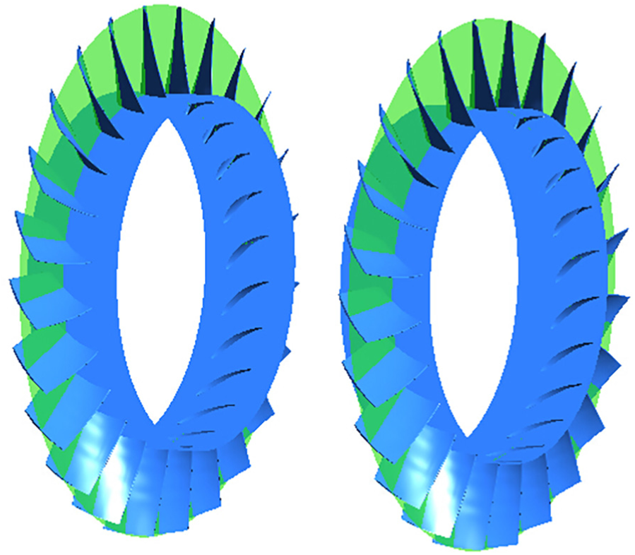
The middle sections of the two rotors.
Figure 10 shows the velocity contours with vectors at an 80% span of the two rotors with respect to the evolutionary process of stall. In this figure, T0 is the design condition, whereas T = 17, T = 18.5, T = 19.5 and T = 34 are the other four typical conditions.

The velocity contours with vectors at 80% span of the two rotors on evolutionary process of the stall: (a) the location of z = 0 mm section; (b) the location of z = 1267.5 mm section.
It can be observed from the figure that in the design condition, the flow field is highly uniform. The flow field begins to become disorderly at T = 17. When T = 18.5, a reverse flow zone appears that occupies two channels in the second rotor. The number of reverse flow zones in the second rotor increases to three at T = 19.5. In the last condition (T = 34), a large area of reverse flow appears in both the first and the second rotor, which indicates that the fan has stalled. The velocity vectors of the reverse flow zone are consistent with the experiment results of Fike et al. 20 for an axial-flow fan at an 80% span.
To highlight the change in the flow field within the rotor before and after the occurrence of rotating stall, the entropy production characteristics of the five previously described typical conditions are analysed. Figure 11 shows the entropy production distribution under the design condition for the first and second rotor. As we can observe, under the design condition, the entropy production distribution within the two-stage rotor is uniform, and the flow conditions of each passage are basically identical. The entropy production of most of the area within the rotor is small due to the stable flow field. However, a high entropy production area exists near each suction surface of the blade tip within the two-stage rotor. In addition, the high entropy production area in the second rotor is somewhat larger than in the first rotor, perhaps because boundary-layer separation and vortex flow appear on the blade tip clearance.
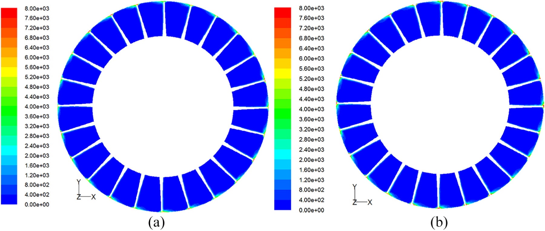
The entropy production distribution of the two rotors under the design condition: (a) the location of z = 0 mm section; (b) the location of z = 1267.5 mm section.
The entropy production distribution under the condition near rotating stall, that is, throttle coefficient k1 = 0.89 (the 17th revolution), of the first and second rotor is shown in Figure 12. The total entropy production in the two rotors is small, and high entropy production areas appear near each blade tip, as in the design condition. The difference is the enlargement of the high entropy production area within the rotor, which contrasts with the design condition. In addition, the high entropy production areas of the second rotor increase obviously. The areas enlarge to the middle region of the passages in the circumferential direction and enlarge to two-thirds of the blade suction surface from the blade tip in the radial direction, respectively. The reason for this phenomenon is that blade-tip leaking flow appears as the rotating stall approaches.

The entropy production distribution of the two rotors near the rotating stall: (a) the location of z = 0 mm section; (b) the location of z = 1267.5 mm section.
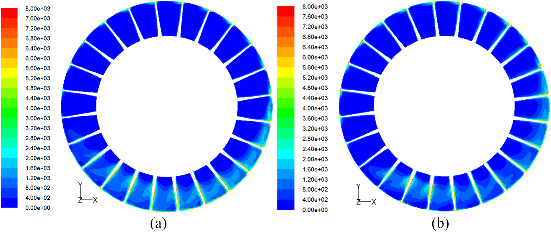
Figure 13 shows the entropy production of the first and second rotor under the condition k1 = 0.811 (i.e. revolution 18.5), when rotating stall occurs. Compared with the z = 0 mm section, that is, in the middle section of the first rotor, an obvious entropy production area appears in the z = 1267.5 mm section, which is the middle section of the second rotor, and the high entropy production band occupies two passages. The entropy production areas near the blade tip of the eight passages, which are counter-clockwise adjacent to the high entropy production band, expand, while the areas of the other passages change slightly. However, the entropy production distribution of the first rotor exhibits no obvious change compared with the 17th revolution. These outcomes indicate that the second rotor enters rotating stall while the first rotor remains stable. That is, rotating stall occurs earlier in the second rotor than in the first rotor.

The entropy production distribution of the two rotors on the stall inception: (a) the location of z = 0 mm section; (b) the location of z = 1267.5 mm section.
There are obvious changes in the areas of entropy production in both rotors (Figure 14; k1 = 0.811, which is revolution 19.5). Compared with Figure 12(a), the high entropy production area in the first rotor has obviously expanded in the circumferential direction. A high entropy production band occupies seven passages, and the band is located near the blade tip. Stall inception occurs in the first rotor at this moment. In the second rotor, the number of high entropy production bands increases from one to three. Each of the three bands occupies three passages, and the interval between them is one passage. Comparing Figures 12 and 13 reveals that the enhancement of flow fluctuation inside the rotor during rotating stall results in an increase in the intensity and an enlargement of the area of the irreversible flow. The behaviour of the irreversible flow in Figure 12 indicates significantly increased entropy production and gradually expanding high entropy production areas in both rotors.

The entropy production distribution of the two rotors during the growth of the rotating stall: (a) the location of z = 0 mm section; (b) the location of z = 1267.5 mm section.
Figure 15 shows entropy production in the condition k1 = 0.811 (i.e. revolution 34). There is a mature stall cell in both sections z = 0 mm and z = 1267.5 mm. Figure 12 indicates that the high entropy production areas (i.e. complete stall cells) occupy 10 passages in the first and second rotor, and they enlarge to half of the blade height. The entropy production area in the other passages is small and concentrated near the blade tip. The areas of high entropy production in the two rotors are nearly the same. However, there is a passage differs in phase of them.
The entropy production distribution of the two rotors on the stall condition: (a) the location of z = 0 mm section; (b) the location of z = 1267.5 mm section.
The analysis of the entropy production distribution of the five typical conditions reveals the entropy production characteristics of the flow field. The evolutionary process of high entropy production during the development of rotating stall in the circumferential and radial directions was obtained. In addition, a detailed understanding of the internal flow field of the rotor after stall was achieved.
Conclusions
In this article, numerical simulation based on the throttle model is performed to study how rotating stall occurs on a variable-speed axial fan with a two-stage pitch. The entropy production characteristics under five typical conditions of the two rotors are analysed. The main results are as follows.
The analysis of relative velocity, which is obtained from monitoring points arranged in the rotor, indicates that rotating stall first occurs in the second rotor. The type of stall inception is a spike.
The analysis of the five typical conditions reveals that the entropy production of the internal rotor gradually increases during rotating stall evolution. After rotating stall occurs, entropy production quickly increases and then reaches a maximum when the stall cell becomes stable. In the entire rotating stall evolution, the entropy production in the second rotor occurs before it did in the first rotor, and the entropy production of the second rotor is higher than that of the first rotor.
Under the design condition, the entropy production distribution inside the rotor is consistent in the peripheral direction, and the flow condition in each passage is basically identical. The entropy production within the two rotors is small. However, small local high entropy production areas exist near the suction surface of each blade tip.
When rotating stall occurred within the internal rotor, the enhancement of the flow disturbance near certain blade-tip passages results in the appearance of a zonal high entropy production area. With the development of rotating stall, the high entropy production area enlarges to three dispersed high entropy production areas. Finally, three decentralized high entropy producing areas are clustered together, with entropy yields reaching the maximum. The phenomenon occurs because the rotating stall enters a relatively stable state, and the number of stall cells decreases from three to one.
Footnotes
Appendix 1
Handling Editor: Yunn-Lin Hwang
Declaration of conflicting interests
The author(s) declared no potential conflicts of interest with respect to the research, authorship, and/or publication of this article.
Funding
The author(s) disclosed receipt of the following financial support for the research, authorship, and/or publication of this article: This research was supported by National Natural Science Foundation of China (Grant No.11602085) and Natural Science Foundation of Hebei Province, China (Grant No. E2016502098).