
Abstract
For tracking control issues of distributed electric-driven agricultural vehicles in the complex road conditions driving state, a 6-degree-of-freedom model of agriculture vehicle was established. On this basis, a mathematical model for control system design was derived using the significant advantages of real-time online estimation of vehicle yaw angular velocity of nonlinear third-order extended state observer. Based on the nonlinear third-order extended state observer, a fast and smooth terminal sliding mode control algorithm was designed using the mathematical model. Afterward, the stability of system was analyzed based on Lyapunov theory. The control algorithm used the fast and smooth terminal sliding mode control instead of the normal terminal sliding mode control required control coefficient matrix inverse calculation, which improved the real-time of the control algorithm. Meanwhile, the smooth sliding mode approach law could converge to the sliding surface in finite time and effectively eliminate chattering, and it had strong adaptability to perturbation and perturbation of system parameters. Simulation and experimental results showed that compared with the traditional nonlinear feedback control algorithm based on nonlinear third-order extended state observer, the proposed control algorithm had short adjustment time, small overshoot and good tracking control accuracy.
Keywords
Introduction
Electric agricultural machinery is an important development direction of future agricultural machinery. 1 In the 1970s, the US General Electric company launched an electric tractor series called the Elec-Trak.2,3 The series of tractors used lead–acid battery power supply and permanent magnet brushless motor as power source and were mainly used for lawn mowing.4,5 Besides, other farm tools can also be selected and matched according to users’ needs. 6 Other companies in the United States are also involved in the development of electric tractors and have a significant portion of their products on the market. For example, Allis-Chalners, an American company, offers electric tractors powered by fuel cells, and the tractor’s speed is achieved by adjusting the number of fuel cells that work.7,8 With the rapid development of power electronics and battery technology, electric agricultural machinery with easy operating, high reliability and multi-functional direction has become the hotspot of agricultural machinery research in the world. 9 Compared with centralized drive vehicles, distributed drive electric vehicles have the following advantages. First, the response of control execution unit is fast and accurate.10,11 Second, the transmission system is highly energy efficient. Third, the compact structure of the vehicle facilitates modular design. Based on the above factors, the distributed electric-driven agricultural vehicles were selected as the research object in the paper.12,13
The observation of vehicle state parameters is the basis of vehicle dynamics control, the accuracy of which largely determines the effect of vehicle dynamics control.14,15 As the distributed drive motor is not only the quick response executive control unit, which can realize the quick and accurate adjustment of driving force and braking force, but also the information unit of the vehicle, which can feedback the current driving torque and driving wheel speed information in real time, so the feedback information from this unit is applied to vehicle state parameter observation, which will further improve the accuracy of vehicle state parameter observation. 16 Therefore, the appearance of distributed electric-driven vehicles breaks the basic way that traditional vehicle dynamics control system can only rely on inertial sensor (INS) and reference wheel speed for vehicle parameter estimation. In addition, combining with the Global Positioning System (GPS), a set of new vehicle key parameter estimation theory and method will be formed.17,18 The application of this new state observation system to dynamic control of distributed electric vehicle will greatly improve and enhance the effect of vehicle dynamic control.19,20
In vehicle dynamics control, vehicle state parameter observation system estimates vehicle key state parameters online and transmits effective information to vehicle controller.21,22 The vehicle controller analyzes the current vehicle status according to the acquired information and then issues corresponding control instructions, so as to achieve effective control of the vehicle. 23 Real-time observation of vehicle status is the basis of vehicle control and the accuracy of state parameter observation directly affects the control effect and characteristics of vehicle dynamics control system.24,25 From the current research status, simple sensors, such as longitudinal acceleration sensor, transverse acceleration sensor, yaw angle velocity sensor, and wheel speed sensor, are widely used to observe vehicle state variables. 26 Since the distributed electric-driven vehicle introduces the direct feedback signal from the driving wheel, the current torque and speed information of each wheel can be acquired in real time, which breaks the basic way that the traditional vehicle dynamics state parameter observation system can only rely on inertial sensor and reference wheel speed to estimate vehicle parameters and is greatly beneficial to estimation of state parameters.27,28 At present, the observation of vehicle status parameters mainly focuses on vehicle motion observation, including longitudinal speed, the sideslip angle, the vehicle yaw rate, auto body pitching angle, auto body inclination angle, tire force observation, vehicle eigen parameters, and pavement state parameters. 29 Aiming at the problem of tracking and controlling the running state of distributed electric-driven agricultural vehicle, a fast and smooth terminal sliding mode control algorithm based on nonlinear third-order extended state observer was proposed in the paper.30,31 The computation real-time performance of the control algorithm was improved using fast smooth terminal sliding mode control without requirement of inverse calculation of coefficient matrix of control variable, which was needed by the conventional terminal sliding mode control.32,33 Meanwhile, the use of the approach law of smooth sliding mode can converge to the sliding mode surface in finite time, effectively eliminate chattering, and adapt well to the parameter perturbation of the system. 34 Compared with traditional nonlinear feedback control algorithm based on nonlinear third-order extended state observer, the proposed control algorithm had advantages of shorter adjustment time, smaller overshoot and better tracking control accuracy. 35
Dynamic modeling of distributedelectric agricultural vehicles
Driving state tracking control problem of distributed electric-driven agricultural vehicles was mainly discussed in this article. First, a 6-degree-of-freedom dynamic model of agricultural vehicle was established. The model could be composed of the translation equation describing the motion of the center of mass with 3 degrees of freedom (equation (1)) and the rotation equation describing the motion around the center of mass with 3 degrees of freedom (equation (2)) and shown as follows:
Translational kinematics equation of the center of mass was shown as follows

where µ,
Kinematics equation of rotation around the center of mass was shown as follows

where α, φ, and γ are the angle of attack, sideslip angle, and inclination angle, respectively; q, f, and i represent rolling, pitch, and yaw angular rate, respectively.
Control system model based onthird-order extended state observer
First, for the convenience of controller design, attitude model was established as shown in equations (3) and (4)


In the formula,

where

was treated as unknown modeling function. Equation (5) was substituted into equation (4) that was the attitude motion equation between attitude angle and control torque, as shown in equation (6)

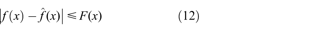
Considering the uncertainty of agricultural machinery model in actual operation and in order to avoid matrix inverse problem, which existed in nonlinear feedback control, sliding mode control, and other controls, equation (6) was processed into equation (7), as shown in the following

where F was estimated value of the main diagonal elements of matrix
Compared with other observers, nonlinear third-order extended state observer, constructed by power function, had advantages of high observation accuracy, independent of the system model, robustness, easy implementation simulation, and actual control.
Nonlinear third-order extended state observer could be used for high precision real-time estimation of system state variables and internal and external disturbances. The perturbations G was set as the third state, equation (8) can be obtained by expanding equation (7), shown as follows

where
where
By reasonable selection of design parameters
The mathematical model suitable for control system design could be exported using nonlinear third-order extended observer combining with equation (6), as shown in the following

where
The design of attitude controller
The problem of driving attitude control of agricultural vehicles with the driving torque control system as the actuator can be summarized as that the driving force moment command of four wheels can be adjusted at any time according to the change of the vehicle’s attitude angle, and finally, the vehicle’s driving attitude can be dynamically tracked as expected. For this reason, aiming at the model uncertainty and external disturbance in practical application, the state variable and internal and external disturbance of the system was observed in real time by nonlinear third-order extended state observer, and the observation error between the observer and the actual disturbance is compensated by sliding mode control.
The establishment of second-order uncertain affine nonlinear system
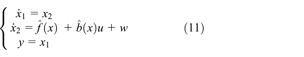
where
In order to meet the design requirements of sliding mode controller, the following hypothesises were put forward.
Assumption 1
The evaluated error of nonlinear smooth function
Assumption 2
The boundary of nonlinear smooth function

Assumption 3
The external interference of the system,

The design of conventional sliding mode controller

The switching function was selected as follows


After taking the time derivative with respect to s, equation (11) was substituted into the derivative, as shown the following

According to equation (17), the sliding mode control law was selected using constant rate approach law, as shown in the following
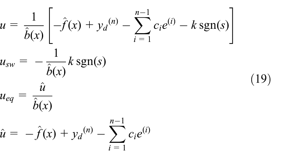
where
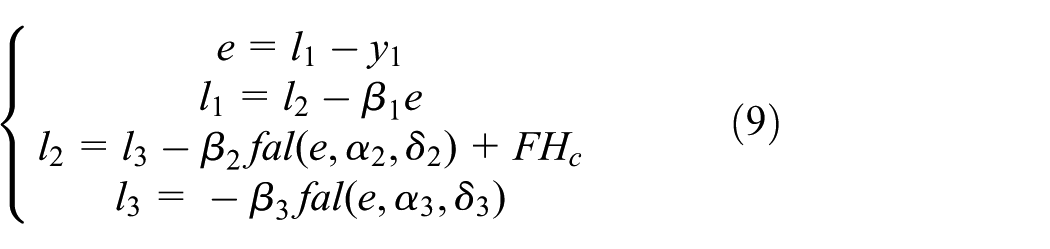
Parameter adaptive sliding mode control based on switching gain and boundary layer thickness
The conventional sliding mode control had the disadvantages of excessive switching gain, constant boundary layer thickness, and requirement for ascertaining the uncertainty boundary. In order to track error, compromise buffeting smoothing, and cancel the demand for knowing the uncertain item boundary of the system, in this article, the bipolar sigmoid function was used instead of the sign function and a parameter adaptive scheme with variable switching gain and boundary layer thickness was proposed.
The design of parameter adaptive sliding mode controller
For the traditional sliding mode control law in the previous section
The control law was considered, as shown in the following

where
For switching gain and boundary layer thickness parameters, the parameter adaptive law was designed, as shown in the following


where
Stability analysis
Under the action of switching function and control law, when the parameter adaptive law sum was adopted, the system was stable and the input buffeting and steady-state errors could be finally eliminated.
Lyapunov function is defined as

Equation (26) was obtained using chain rule, as shown in the following

Equation (24) was substituted into equation (26) and equation (27) was obtained


Equations (23) and (24) were substituted into equations (27) and (28), respectively, and equations (29) and (30) were obtained


Therefore, as
Simulation verification
The control system model based on nonlinear third-order extended state observer was adopted for simulation as shown in equation (10). The conventional sliding mode controller and the parameter adaptive sliding mode controller based on the compensation design of third-order extended state observer were applied to the attitude angle tracking control of distributed electric-driven agricultural vehicles. The initial conditions were as follows: V1 = 10 km/h,
Case 1
The simulation method was used to compare the vehicle running state parameters obtained by real-time monitoring under two different modes of parameter adaptive sliding mode control designed in the paper and conventional sliding mode control. The experimental vehicle ran at a speed of 10 km/h and simulation analysis was conducted under the preset road conditions.
The simulation results were shown in Figures 1–5. Figures 1–5 shows the tracking and control curves of the running speed, the sideslip angle, the yaw rate, the horizontal pendulum angle, and the tracking and control curve of the steering wheel angle of agricultural vehicles during operation. By compared adaptive sliding mode control with conventional sliding mode control, it could be found that although both the two control methods could keep the vehicle in a stable area, the maximum sideslip angle in the adaptive sliding mode control process was only 3.49, which was lower than the maximum sideslip angle of 4.91 in the conventional sliding mode control process, indicating that the control effect of adaptive sliding mode control is better than that of traditional sliding mode control.

The tracking and control curve of the running speed when the experimental vehicle ran at a speed of 10 km/h.
The tracking and control curve of the sideslip angle when the experimental vehicle ran at a speed of 10 km/h.

The tracking and control curve of the yaw rate when the experimental vehicle ran at a speed of 10 km/h.

The tracking and control curve of the horizontal pendulum angle when the experimental vehicle ran at a speed of 10 km/h.

The tracking and control curve of the steering wheel angle when the experimental vehicle ran at a speed of 10 km/h.
In order to compare the control effects of the two different control methods, the maximum of sideslip angle
The simulation results of driving attitude control when the experimental vehicle ran at a speed of 10 km/h.

Case 2
The simulation method was used to compare the vehicle running state parameters obtained by real-time monitoring under two different modes of parameter adaptive sliding mode control designed in the paper and conventional sliding mode control. The experimental vehicle ran at a speed of 20 km/h and the simulation analysis was conducted under the preset road conditions.
The simulation results are shown in Figures 6–10. Figures 6–10 shows the tracking and control curves of the running speed, the sideslip angle, the yaw rate, the horizontal pendulum angle, and the tracking and control curve of the steering wheel angle of agricultural when vehicles are mobile. The maximum sideslip angle in the adaptive sliding mode control process was 9.7, which was lower than the maximum sideslip angle of 12.2 in the conventional sliding mode process, indicating that the control effect of adaptive sliding mode control was more optimized. The maximum of sideslip angle

The tracking and control curve of the running speed when the experimental vehicle ran at a speed of 20 km/h.

The tracking and control curve of the sideslip angle when the experimental vehicle ran at a speed of 20 km/h.

The tracking and control curve of the yaw rate when the experimental vehicle ran at a speed of 20 km/h.

The tracking and control curve of the horizontal pendulum angle when the experimental vehicle ran at a speed of 20 km/h.

The tracking and control curve of the steering wheel angle when the experimental vehicle ran at a speed of 20 km/h.
The simulation results of driving attitude control when the experimental vehicle ran at a speed of 20 km/h.

Road test verification
The distributed electric-driven agricultural vehicle prototype, used in the test, was designed and manufactured by the research group. The appearance of the vehicle is shown in Figure 11 and the main parameters of the distributed electric vehicle experimental platform are shown in Table 3. The electronic driving technology, remote control technology, and database storage technology were applied to realizing real-time control of vehicle running state.
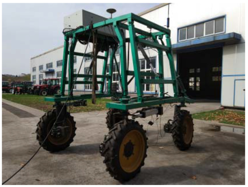
Distributed electric-driven agricultural vehicle experimental platform.
The parameters of the distributed electric vehicle experimental platform.

The principle of vehicle running state control circuit
The circuits involved in the experiment included main power switch control circuit, target controller programmable logic controller basic control circuit, remote controller circuit, adjustable electric cylinder circuit, electronic steering servo motor circuit, main drive servo motor circuit, and GPS acceptor circuit. The diagram is shown in Figure 12.
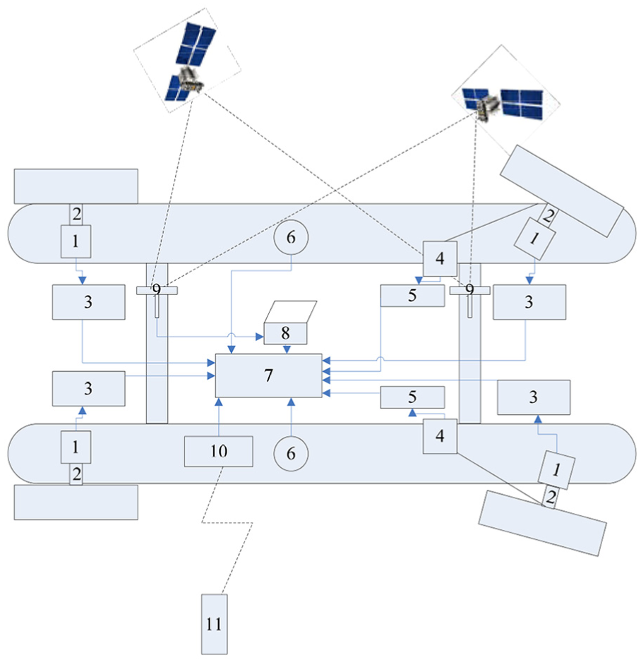
Hardware device.
The site of this test was the open land of Jiangsu agricultural machinery test and identification station. The grass soil pavement newly grown in the site was selected (see Figure 13). Since the site was about 30 m long and the points collected in each test of the vehicle were about 50, a large number of tests were needed to verify the conclusion.
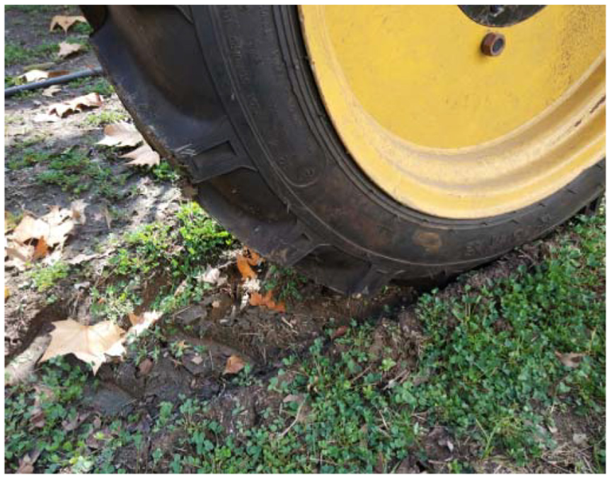
Road conditions of the experimental site.
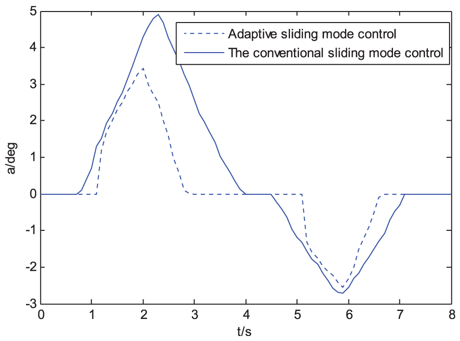
Figure 14 shows the speed change curves of the experimental vehicle under the conditions of operating speed at 10 km/h and maneuvering speed at 20 km/h on the selected experimental road surface under the conditions of adopting different control strategies. Agricultural vehicles traveled at a target speed of 10 km/h and at the beginning of the experiment, the two control strategies can well control the speed near the target speed. At 9.1 s, speed under adaptive sliding mode control was more closer to target speed, indicating that the control effect of adaptive sliding mode control was evidently better than conventional sliding mode control algorithm. Agricultural vehicles traveled at a target speed of 20 km/h and at the beginning of the experiment, adaptive sliding mode control could well control the speed near the target speed, while conventional sliding mode control deviates from the target speed, and at 3.9 s, the maximum deviation velocity was reached. At 8.9 s, both control algorithms can well control the speed near the target speed. Therefore, the adaptive sliding mode control could well control the vehicle driving near the target speed when the vehicle drove at different speeds, which confirmed the control effect of adaptive sliding mode control was evidently better than conventional sliding mode control algorithm.

The tracking and control curve of the running speed under the conditions of adopting different control strategies.
Figure 15 shows the tracking and control curve of the sideslip angle under the conditions of operating speed at 10 km/h and maneuvering speed at 20 km/h on the selected experimental road surface under the conditions of adopting different control strategies. As can be seen from Figure 15, with the change of road surface concave and convex, the sideslip angle of agricultural vehicle also changed correspondingly. When the vehicle traveled at 10 km/h, the maximum sideslip angle appeared at 5.2 s and when the vehicle ran at 20 km/h, the maximum sideslip angle appeared at 2.47 s. Therefore, both control algorithms successfully control the vehicle sideslip angle in a controllable range, but the parameter adaptive sliding mode control algorithm had better control effect and made the sideslip angle smaller; thus, the stability of the vehicle was increased.
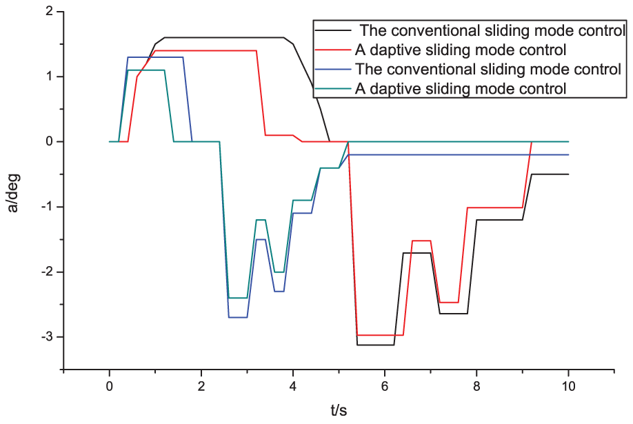
The tracking and control curve of the sideslip angle under the conditions of adopting different control strategies.
Figure 16 shows the tracking and control curve of the yaw rate under the conditions of operating speed at 10 km/h and maneuvering speed at 20 km/h on the selected experimental road surface under the conditions of adopting different control strategies. As can be seen from Figure 16, when the vehicle traveled at 10 km/h, the maximum yaw rate of the vehicle controlled by the parameter adaptive sliding mode control is 1.1°/s, which was lower than 1.3°/s of conventional sliding mode control algorithm. Meanwhile, when the vehicle traveled at 20 km/h, the maximum yaw rate of the vehicle controlled by the parameter adaptive sliding mode control was 4.1°/s, which was lower than 4.5°/s of conventional sliding mode control algorithm. Therefore, both control algorithms successfully control the vehicle yaw rate in a controllable range, but the parameter adaptive sliding mode control algorithm had better control effect; thus, the stability of the vehicle was increased.
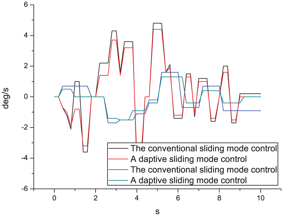
The tracking and control curve of the yaw rate under the conditions of adopting different control strategies.
Conclusion
The control algorithm based on nonlinear third-order extended state observer, which was designed in the paper, started directly from the mathematical model (equation (10)) of the control system design. As the algorithm was simple, the adjustment is convenient, the computation quantity is small, and the implementation of online was easy to implement, so the proposed control algorithm is more suitable for the practical application of attitude angle controller in the process of agricultural vehicle operation. The fast and smooth terminal sliding mode control, which did not need the inverse calculation of the coefficient matrix of control variables required by the conventional terminal sliding mode control, was adopted to improve the real-time performance of the control algorithm. Meanwhile, the use of the smooth sliding mode approach law can converge to the sliding mode surface in a finite time, effectively eliminate chattering, and have strong adaptability to the parameter perturbation and disturbance of the system. The simulation results revealed that compared with conventional synovial control algorithm based on nonlinear third-order extended state observer, the parameter adaptive control algorithm, proposed in the paper, had advantages of short adjustment time, small overshoot, high tracking accuracy, and certain engineering application value. In this work, the concept of attitude control was first applied to agricultural vehicles, and in view of the complexity of the working environment of agricultural vehicles and the specific working background, a parameter adaptive control algorithm based on real-time online estimation was proposed. The research results showed that the parameter adaptive control algorithm has advantages of strong practicability and good real-time performance and had certain reference significance for the research on intelligence of agricultural machinery.
Footnotes
Appendix 1
Handling Editor: ZhiWu Li
Declaration of conflicting interests
The author(s) declared no potential conflicts of interest with respect to the research, authorship, and/or publication of this article.
Funding
The author(s) disclosed receipt of the following financial support for the research, authorship, and/or publication of this article: This work was financially supported by the national key research and development plan (no. 2016YFD0701003).