
Abstract
Laser printer internal parts are prone to deformation when they are working in high temperature environment for a long time, resulting in machine faults such as paper jam and angle folding. In order to predict the deformation of parts in thermal environment and further determine their initial allowable deformation, so as to guide the structural design and production process of parts, and to reasonably determine the stress mode of parts in the working process, the structural deformation of the complex injection part-fuser upper cover in a laser printer after long-term operation in thermal environment is studied. First, on the basis of fusing temperature control technology and heat exchange analysis of the whole machine, the internal temperature field of a laser printer is numerically simulated by using the flow and heat transfer analysis software, and the temperature data of the key parts inside the machine are obtained more accurately. Then, the sequential coupling method is used to apply the results of thermal analysis of the whole machine as the external loads of static stress analysis to the fuser upper cover model, and the structural thermal deformation data of the fuser upper cover are obtained.
Keywords
Introduction
The fusing process of a laser printer is to melt and infiltrate the unfixed toner into the paper fibers to form a fixed image through the action of high temperature and pressure of the fuser mechanism. High temperature fusing is an indispensable step for a laser printer. However, the structure of the laser printer is becoming smaller and more compact, and the printing speed is getting faster and faster, which makes it difficult for the printer to dissipate heat after long-term use. Consequently, it is maintained at a higher internal temperature for a long time. The main paper guide parts in laser printer are mostly injection parts, especially in the fuser mechanism. The creep properties of the materials make the structural deformation of the parts greatly affected by temperature.1,2 After printing continuously for a long time, the deformation of fusing parts will cause paper jam, folding, wrinkle, and other problems. Therefore, studying the thermal deformation of the key parts in the fuser mechanism of the laser printer to guide its structural design has more practical significance for improving the structural design level of the whole machine and the printing quality of the laser printer.
Scholars have carried out relevant research on the internal structure of printers and photocopiers: Chen 3 used the multi-body dynamics software DADS to carry out a comprehensive analysis of the design parameters such as roller material, contact force between roller and paper, and paper feeding speed, which is helpful to guide the design of paper feeding mechanism. The properties of paper feeding mechanism of a printer with rubber roller were simulated with finite element analysis software by Yanabe et al.,4–6 and the optimum matching angle, contact force, and transmission speed of the paper feeding roller were obtained. The slip characteristics between the rubber paper feeding roller and the paper transferred were studied. Kawamoto and Umezu 7 proposed a new electrostatic paper separating and feeding system, and demonstrated that stable and continuous paper separating and feeding are possible at speed in excess of 600 mm/s, yielding separation of 100 sheets of A4 size paper per minute. Liang 8 studied the design parameters of the paper picking and feeding mechanism of the printer from the aspects of paper feeding angle and the position relationship between the paging pad and the paper picking roller. Wang et al.9–11 used the RecurDyn software to simulate the paper picking and separating of the copier, and simulated the conveying mechanism. The effects of the positive pressure of rollers and the angle of the paper feeding guide on the paper conveying stability were obtained.
These studies mainly focus on the paper-picking and separating mechanism of printers and photocopiers but few on the fuser mechanism, especially the structure of related parts. In addition, the existing thermal response analysis of parts mostly adopts the method of directly imposing temperature boundary conditions, and does not place the analysis object in the whole machine environment.
Structure of the fuser mechanism is complex and it works in high temperature environment for a long time, which is the key to affect the printing quality. The thermal condition of the internal parts of the printer is directly affected by the internal structure layout and the temperature field of the whole machine. Therefore, in order to get a more accurate temperature distribution of a single analysis object, it is necessary to proceed from the point of view of the whole machine. Based on this, first, a key part of the fuser mechanism is taken as a novel research object in this article. Second, based on a real laser printer, the temperature field inside the whole machine is simulated and analyzed by CFD (Computational Fluid Dynamics) software, so as to get the temperature field of the whole machine and its influence on the key parts inside. The temperature results of the parts based on the analysis of the whole machine temperature field are more accurate than those obtained by directly applying boundary conditions. Structural optimization design of complex injection molding parts is a non-linear design process involving different coupled disciplines. 12 The thermal analysis results extracted from the temperature field analysis of the whole machine are loaded as external loads into the static stress analysis of the fuser upper cover in this article, and the structural response of the fuser upper cover under the thermo-mechanical coupling is obtained. The method used in this article has higher accuracy and efficiency, and can be widely used to predict the deformation of parts in thermal environment, determine the allowable initial deformation of parts, guide the design of parts, and adjust the production process.
Internal structural of the laser printer
The main technical parameters of the laser printer selected in this article are listed in Table 1.
Main technical parameters of the laser printer.

The overall structure of the printer is shown in Figure 1(a), and the inner machine core is covered by an integral housing. Figure 1(b) is the internal profile of the printer. The internal machine core is mainly composed of a main frame component, a paper cassette, a cartridge, a laser scanning component, a fuser mechanism, a transmission mechanism, a power supply board, a main control board, and so on. The arrow curve in Figure 1(b) points out the route of paper inside the printer, and the parts related to guide paper are clearly visible.
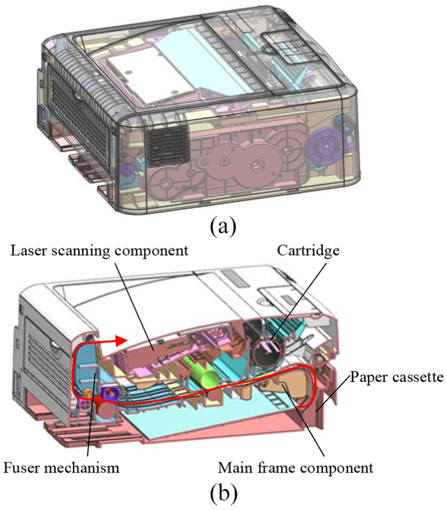
Model of the laser printer: (a) overall structure of the laser printer and (b) internal structure of the laser printer.
The fuser mechanism is located at the back of the whole machine. It consists of a fuser upper cover, a fuser lower cover, a heating roller, a pressure roller, a halogen lamp, several separating claws, and so on 13 as shown in Figure 2. The fuser mechanism mainly completes the high-temperature fusing of toner on paper and participates in the transmission of paper. The heating roller is a seamless aluminum alloy tube coated with polytetrafluoroethylene (PTFE), which is semi-contained at the bottom of the fuser upper cover and is in close contact with the pressure roller made of high temperature resistant silica gel. The halogen lamp is the main heat source of the whole machine, and its power is generally 600–850 W. The halogen lamp is fixed in the center of the heating roller and does not rotate with it to heat the heating roller. The paper passes between the heating roller and the pressure roller under the guidance of the fuser upper cover and the fuser lower cover. The toner image fusing is completed under the action of high temperature and pressure. The arrow curve in Figure 2 represents the paper’s route.
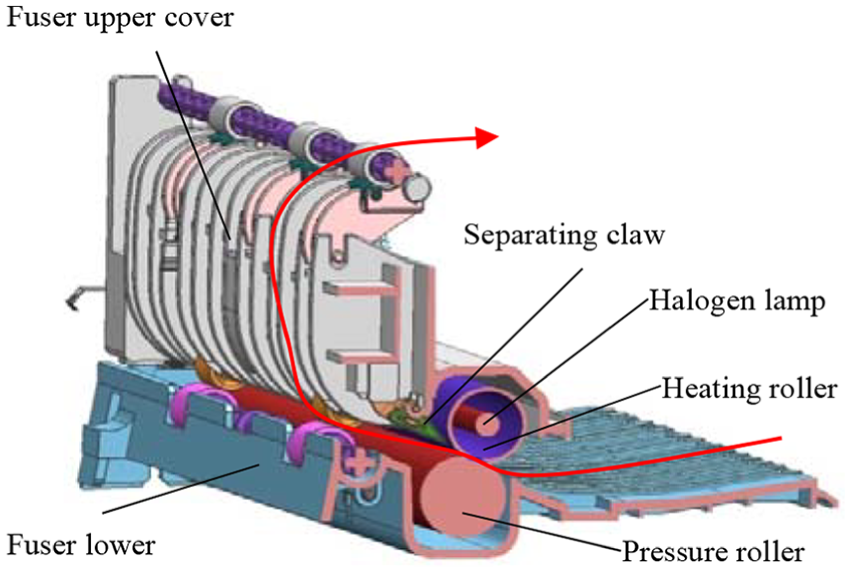
Structure of the fuser mechanism.
The fuser upper cover is a key part in the fuser mechanism. It is used for supporting and fixing other parts in the fuser mechanism, and also participates in the paper transmission process after fusing. The fuser upper cover is injection molded with PET+GF30% material, and its structure is complex. The structure and outline dimension of fuser upper cover are shown in Figure 3. Under normal temperature, the design requirement of warpage deformation in the length direction of the fuser upper cover is ±0.3 mm. In the production process of fuser upper cover, the finished product can meet the design requirements by strictly controlling the injection process. However, in the long-term use of the printer, the fuser upper cover is affected by high temperature in the whole machine for a long time, and the deformation will occur as shown in Figure 4. Deformation of the fuser upper cover will change the position of the transmission parts fixed on it, especially the deformation of the back guide ribs will affect the normal movement of the paper after fusing, and cause the problems of paper jam and paper angle folding.14,15

Structure and outline dimension of the fuser upper cover.
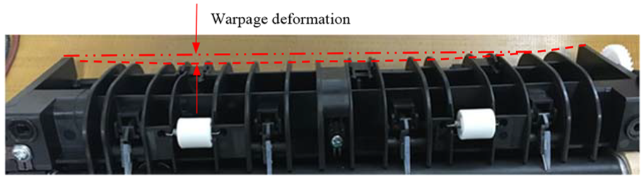
Deformation of the fuser upper cover.
Analysis of temperature field in the laser printer
Fusing temperature control technology of the laser printer
It can be seen from the foregoing that the laser printer finishes the fusing work by the action of high temperature and pressure between heating roller and pressure roller. If the surface temperature of the heating roller is too high, that is, if the fusing temperature is too high, the paper and the heating roller are easy to stick together, which leads to the abnormal operation of the fuser mechanism; otherwise, the image fusing is not firm if the fusing temperature is too low. Therefore, the surface temperature of the heating roller in the fusing process needs to be maintained at a relatively suitable and stable temperature, generally 160°C–180°C, which is related to the composition of the toner used by the printer.
The fusing temperature control of laser printer is accomplished by the temperature sensor on the outer surface of heating roller and the corresponding control program.16,17 The halogen lamp is turned on when there is a print signal, and the heating roller is heated up to the fusing temperature and kept at that temperature. Then, the main controller sends out a print signal. After the halogen lamp is turned on, the main controller will turn off the halogen lamp timely according to the current temperature and the temperature rise of the heating roller detected by the temperature sensor, and continue to judge the next time when the halogen lamp is turned on, so as to control the heating time and frequency of the halogen lamp. This process of closing and reopening the halogen lamp will cause temperature fluctuations on the surface of the heating roller, but it will remain at a relatively stable temperature ultimately, as shown in Figure 5.
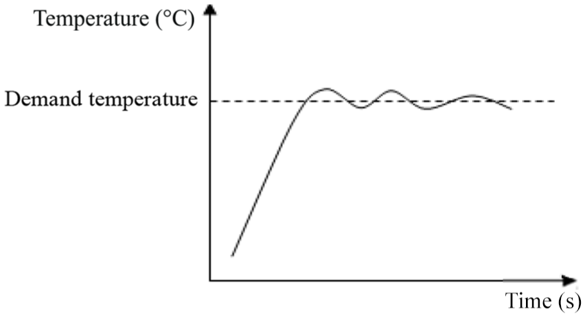
Fusing temperature control curve of laser printer.
Analysis of heat exchange in the laser printer
The fuser upper cover is located inside the printer, and its heating condition is related to the temperature field inside the whole machine. Therefore, the temperature field inside the printer should be analyzed from the point of view of the whole machine in order to get a more accurate temperature distribution of the fuser upper cover.
Figure 6 shows a 230 V, 700 W halogen lamp 18 used in this laser printer, mainly composed of a filament, a lamp tube, two outer leads, and two terminals. Among them, the filament is made of tungsten wire; the lamp tube is made of quartz glass and filled with high pressure argon; the outer lead is made of molybdenum wire; and the terminal is made of stainless steel.

Halogen lamp of laser printer.
The input electric power of the halogen lamp is transformed into heat energy on the filament, and the filament temperature can reach about 3000°C. The high temperature filament exchanges heat with the surrounding halogen gas in the form of convective heat transfer. Because the halogen lamp is located in the center of the heating roller and the fluid space is small, most of the energy on the filament will be projected through the lamp tube wall to the inner surface of the heating roller in the form of thermal radiation. The heating roller absorbs heat and its temperature rises. Some heat of the heating roller transmits inside the printer in the form of convective heat transfer, and some heat is transmitted in the form of heat conduction. Therefore, there are three ways of heat transfer in the printer: heat conduction, heat convection, and heat radiation.
The heat dissipation of the parts in the laser printer is mainly forced convection cooling through the fan.
Numerical calculation of internal temperature field in the laser printer
For systems with internal heat sources, when the heat generation rate of the heat source in the system is the same as the heat exchanged between the system and the outside, the heat steady state is reached 19 and the temperature of the system reaches its maximum. Aiming at the standby state of laser printer, the steady-state analysis of temperature field in the whole machine under the condition of forced convection is carried out in this article.
Computing method
The FloEFD software used in thermal analysis of printer in this article is a versatile CFD tool, which uses finite volume method 20 to solve fluid and heat transfer numerically. The finite volume method is used to discretize the differential equations at grid nodes to obtain the algebraic equations. The algebraic equations are solved by introducing the boundary conditions, and the temperature at each grid node is obtained. The solution process is shown in Figure 7.

Solution process of FloEFD.
The steady-state simulation of temperature field in printer is carried out in this article. There are three ways of heat transfer inside the printer that includes heat conduction, heat convection, and heat radiation. The governing equations for the analysis in this article are listed below from equations (1)–(5), according to the first step in Figure 7.
Differential equation of heat conduction: The basic governing equation of solid heat transfer is heat conduction differential equation. According to Fourier’s law and energy conservation law, the three-dimensional unsteady heat conduction differential equation with internal heat source is as follows 21

In this formula,
Differential equation of heat convection: The convective heat transfer in printer mainly depends on air fluid. The governing equation of fluid is used to describe the heat transfer and flow process of fluid, including mass conservation equation, momentum conservation equation, and energy conservation equation. 22
Mass conservation equation: This equation is also called continuity equation, which describes the continuity conditions that must be satisfied in fluid motion. It shows that the algebraic sum of the difference of mass between outflow and inflow and the change of internal mass is zero when the fluid flows through unit volume space in unit time. The continuity equation in differential form is as follows

In this formula,
Momentum conservation equation: This equation describes the dynamic conditions that flow satisfies. It is the mathematical expression of momentum theorem in flow field. Its differential form is as follows

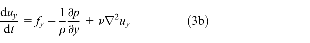

In the formula, f is the unit mass force, p is the surface force distribution function on the unit area, and
Energy conservation equation: It is used to describe the change of fluid temperature or energy. It is the expression of the law of conservation of energy in fluid motion. Its differential form is
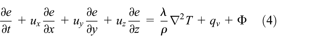
In the formula, e is the energy per unit mass of fluid, and the consumption function is

Thermal radiation governing equation: Heat radiation and radiation heat transfer are essentially different from heat conduction and convection heat transfer processes. The conservative equation on which heat conduction and convection heat transfer are calculated cannot be applied in the calculation of radiation heat transfer. The problem of radiative heat transfer in simple radiative heat transfer state in engineering can be described by algebraic equation.23,24 Radiation heat transfer complying with Stephen–Boltzmann Law

In this formula, Q is the heat radiated by an object to the cavity surrounding it,
Creating flow analysis model
The consistency between physical model and real object has great influence on the simulation accuracy of temperature field. The shape, size, and position of components determine the flow state of the fluid, thus affecting convective heat transfer and heat conduction. Because the internal structure of the laser printer is complex and there are many parts in it, it is necessary to simplify the parts which have less influence on the heat exchange of the whole machine, so as to minimize the amount of calculation without affecting the accuracy of simulation. Running “Model Check” and “Create Seal” to get fluid volume: 0.01156 m3 and the solid volume is 0.0055 m3, the overall flow analysis settings are shown in Table 2.
Parameters of flow analysis.

Specifying fluid subdomain
The halogen lamp used in this article is filled with high pressure argon; we use fluid subdomain to define both the gas filling the lamp and its pressure. Select the inner cylindrical face of the lamp tube, and the inner space of the lamp tube is defined as the fluid subdomain. Fluid type is argon, pressure is 300,000 Pa, and the initial temperature is 293.2 K.
Specifying boundary conditions
A boundary condition is required in any place where fluid enters or exits the model, excluding openings where a fan is specified. Therefore, the pressure openings are defined on the inner surfaces of all openings in the paper outlet and the back panel as environment pressure is 101,325 Pa and temperature is 293.2 K.
The outer wall condition on the surfaces of the printer housing are adjust wall heat transfer coefficient is 10 W/m2/K and external fluid temperature is 293.2 K.
Specifying an external outlet fan according to the actually fan type KF0420-2HS used in the laser printer, the environment pressure is 101,325 Pa and the fan characteristic curve of is shown in Figure 8.
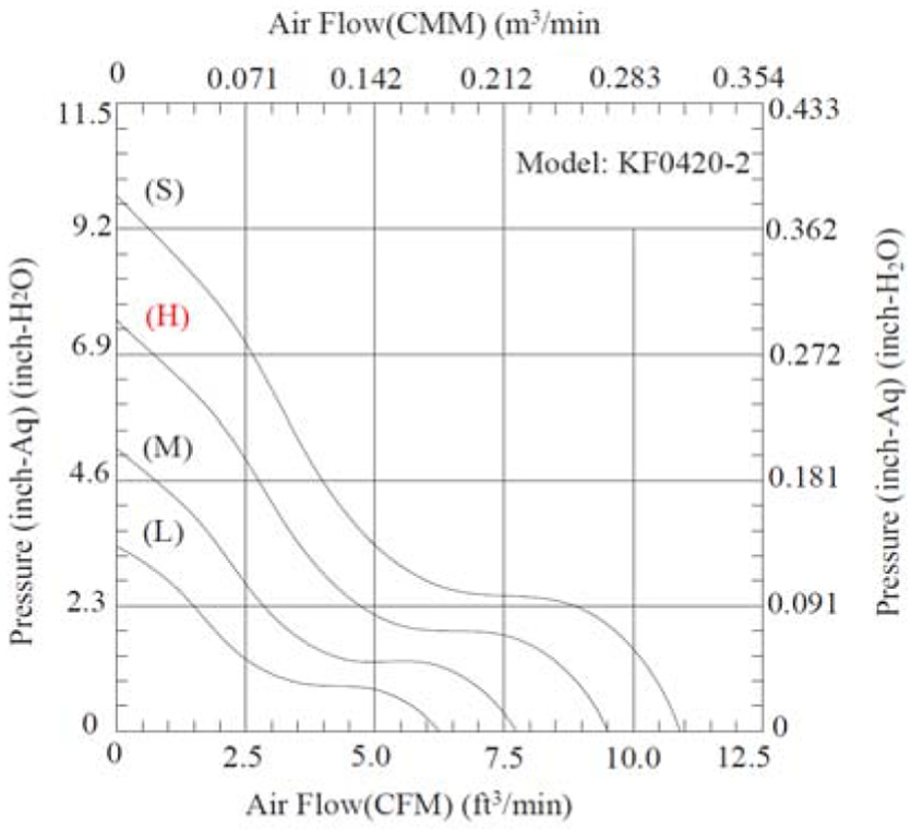
KF0420-2HS fan characteristic curve.
Specifying heat and radiation conditions
Specifying heat sources: From the previous analysis, we can see that halogen lamp is the main heat source of the laser printer, and its heating time is related to the temperature of the outer surface of the heating roller. According to the control relationship between the halogen lamp and the outer surface temperature of heating roll, the heat source is set as dependency type: set the surface temperature of the heating roller as a goal, and the control temperature is 443 K, that means, when the surface temperature of the heating roller is higher than 443 K, the halogen lamp stops heating. As a heat source, the filament has the same heat generation rate as the actual working state. The definition of heat source is shown in Figure 9.
In addition, the internal power supply board and the main control board of the printer are defined as volume heat source with heat generation rate of 20 W totally.
Specifying radiative surfaces: Two radiative surfaces need to be defined in this model. The outer surface of filament is defined as radiative surface 1: pre-defined/real surfaces/tungsten, filament; the inner surface of heating roller is defined as radiative surface 2: pre-defined/real surfaces/aluminum, highly oxidized.

Definition of “goal dependent” heat source.
Setting local initial mesh
Mesh is the geometric expression of CFD simulation model and the carrier of simulation analysis. The quality of mesh has an important influence on the efficiency and accuracy of CFD solution. 25 In this article, the method of manual meshing is used to set up the basic mesh and local refinement, and the mesh is refined automatically according to the geometric model and the adaptive requirements of solution. The halogen lamp, fuser upper cover, fuser lower cover, and separating claw with larger temperature gradient are set with advanced refinement and the small size parts or channels are self-adaptively refined. Finally, 3,479,367 cells were obtained, including 1,807,581 solid cells and 1,671,786 fluid cells.
Results of thermal calculation
It can be observed through the solver window in the process of solving that the temperature of each goal varies with the number of iterations. Figure 10 is the temperature curve of the outer surface of the heating roller which converges after 236 iterations. The curve is basically consistent with the temperature control curve of the laser printer as described above, which reflects the radiation heat transfer process between the halogen lamp and the heating roller: when the surface temperature of the heating roller reaches 443 K, the halogen lamp stops heating and the temperature of the halogen lamp decreases gradually. But at this time, the heat absorbed by the heating roller through thermal radiation is larger than the heat released, so the surface temperature of the heating roller continues to rise and reach the maximum value until the heat absorbed by it is equal to the heat released, and then it begins to drop. When the surface temperature of the heating roller drops to 443 K, the halogen lamp begins to heat and the temperature of the halogen lamp increases gradually. But at this time, the heat absorbed by the heating roller is less than the heat released, so the temperature of the heating roller continues to drop and reach the minimum value until the heat absorbed by the heating roller is equal to the heat released; it goes on circulating like this.

Surface temperature curve of heating roller.
After calculating, the internal flow trajectories of printer, the temperature distribution of the whole machine, and the temperature distribution of the fuser upper cover are obtained.
Figure 11 shows the internal flow trajectories of the printer shown by temperature. It can be seen that the high temperature of the fluid mainly concentrates near the fuser mechanism. The air flow in the whole machine is smooth, and there is no vortex. The heat dissipation in the whole machine is good, and the air temperature gradient is large.

Internal flow trajectories of printer.
Figure 12 shows the temperature distribution of the parts inside the printer. The temperature of the parts inside the printer and the temperature difference between them can be seen from the figure. The overall temperature field presents a distribution trend of halogen lamp centered and gradually decreasing around. Most of the injection parts in the machine are made of ABS plastic with deformation temperature of about 360 K. Therefore, we focus on parts with temperature distribution of 360 K or more: halogen lamp, heating roller, separating claw, pressure roller, fuser upper cover, fuser lower cover, and so on. Their temperature is relatively high. In addition, the temperature of the power supply board and the main control board also increased due to their own heating and forced convection heat dissipation. The temperature of other parts in the printer and the fluid far away from the fuser mechanism is kept at room temperature.

Temperature distribution of internal parts.
Figure 13 is the temperature distribution chart of the fuser upper cover. It can be seen that the temperature field gradient of the fuser upper cover is larger, and it is centered on the semi-enclosure structure nearest to the heating roller and gradually decreases in the direction of the back guide ribs. The highest temperature is 359 K, near the cantilever corresponding to the left end of the heating roller on the front side of the fuser upper cover, while the temperature of the back guide ribs is kept at room temperature. The fuser upper cover is made of PET+GF30% material with deformation temperature of about 500 K. It can be seen that the highest temperature of the part is lower than the thermal deformation temperature of the material.
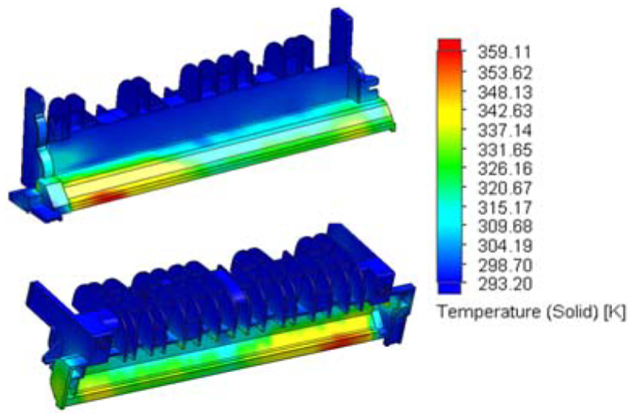
Temperature distribution of fuser upper cover.
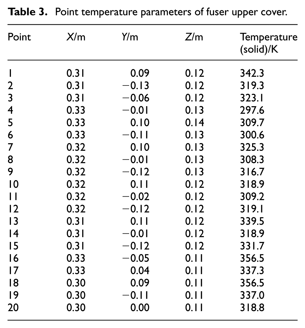
In addition, by selecting the key points on the surface of the part, the quantitative parameters of the points can be obtained, including coordinate values, solid temperature, fluid temperature, heat flux, and pressure. Temperature parameters of the key points close to the heating roller on the fuser upper cover are given in Table 3.
Point temperature parameters of fuser upper cover.
Thermo-mechanical coupling analysis of the fuser upper cover
There are two general finite element methods for thermo-mechanical coupling response: direct coupling method and sequential coupling method. In order to get more accurate temperature results of the fuser upper cover, the flow and heat transfer analysis software is used in this article and the temperature results of the fuser upper cover are based on the analysis of the whole machine. The temperature results of the fuser upper cover are extracted from the temperature field results of the whole machine and then loaded into the static stress analysis for thermo-mechanical coupling analysis. Therefore, the sequential coupling method is more conducive to this analysis. In this article, the sequential coupling method is used to calculate the overall thermo-mechanical coupling response of the structure so as to analyze the thermal deformation of the fuser upper cover.26–28
Establishing a static stress analysis project
A static stress analysis is established for the fuser upper cover model.
Setting material properties: setting the same material characteristics as the previous thermal analysis to the model, as shown in Table 4.
Applying loads: two kinds of external loads are required for thermo-mechanical coupling analysis of the fuser upper cover.
Thermodynamic effect loads: The results of the flow and heat transfer analysis above are loaded on the fuser upper cover model as external loads. Setting the thermodynamic effect as “flow simulation temperature” and setting the reference temperature at zero strain as 20°C. The thermodynamic effect loads can be displayed on the model, as shown in Figure 14.
Displacement loads: The fuser upper cover is fixed on the internal machine core through four screws at the bottom and front of it. Therefore, the fixing constraint is set on the four screw faces of the fuser upper cover, as shown in Figure 14.
Meshing: Meshing the model with element type of solid, the total number of nodes is 32,708 and the total number of elements is 16,139.
Material properties of fuser upper cover.


Applying loads to fuser upper cover.
Results of thermo-mechanical coupling calculation
Operating the static stress object, the results of thermo-mechanical coupling calculation of the fuser upper cover are shown in Figures 15 and 16.

Stress distribution of fuser upper cover.
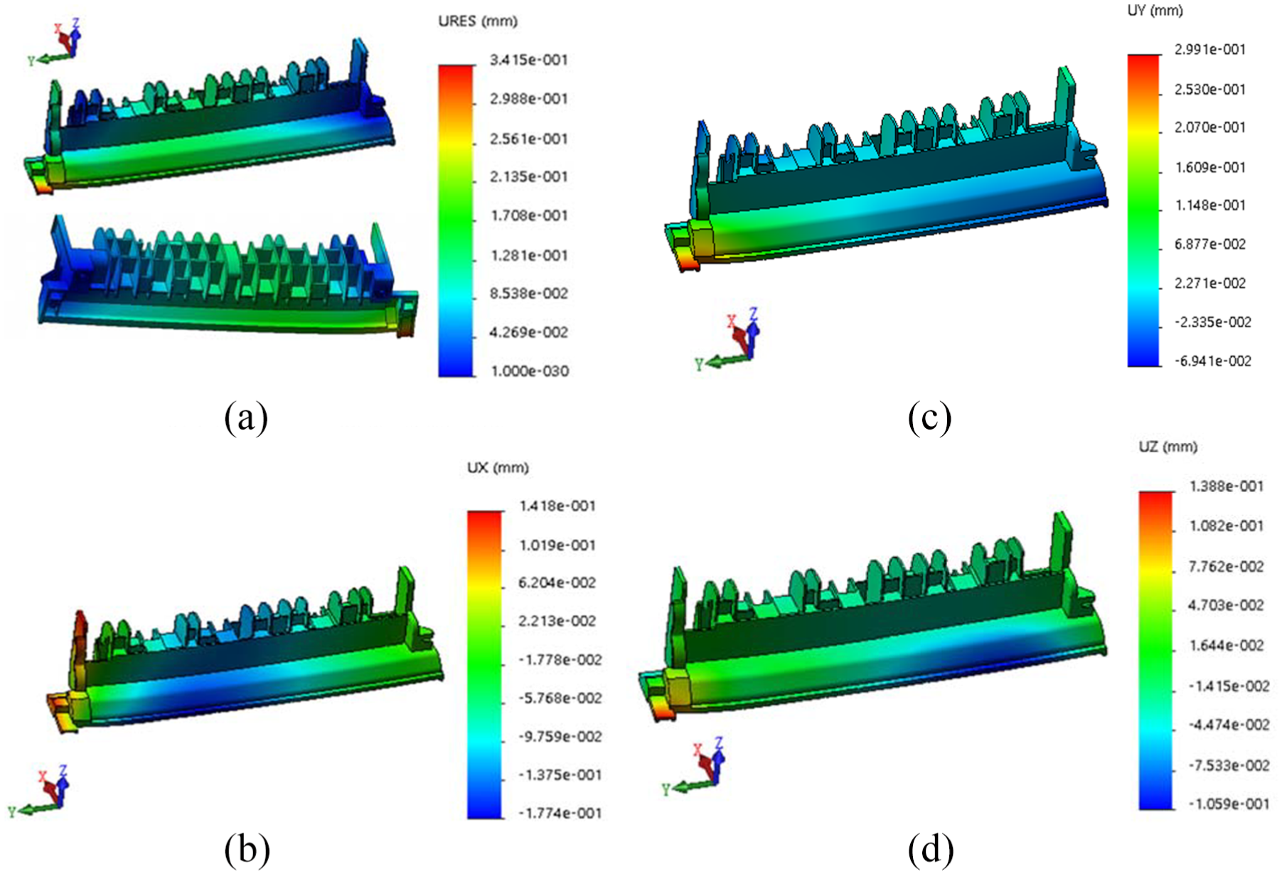
Displacement distribution of fuser upper cover: (a) resultant displacement distribution, (b) displacement distribution of X component, (c) displacement distribution of Y component, and (d) displacement distribution of Z component.
According to the stress distribution figure of fuser upper cover, the maximum stress of the fuser upper cover under the influence of temperature is 13.63 MPa, which is located at the screw connection and has a large stress gradient. According to the displacement distribution figure of fuser upper cover, the maximum resultant displacement of the fuser upper cover is 0.34 mm under the influence of temperature, which is located at the cantilever corresponding to the left end of the heating roller. The maximum displacement in X direction is 0.14 mm, in Y direction is 0.29 mm, and in Z direction is 0.13 mm.
Discussion and application of calculation results
Discussion on the results of calculation
As a key part of printer, the fuser upper cover can be used in production only after strict incoming material inspection. The inspection is usually carried out at room temperature and the warpage deformation of the fuser upper cover in the length direction should be within ±0.3 mm. But even if the parts are inspection qualified, there will still be excessive deformation after long-term use.
In this article, the fuser upper cover model used in analysis is an original design model without initial deformation. The results show that when the printer works for a long time, the maximum deformation in Y direction of the fuser upper cover is 0.29 mm, and the maximum total deformation is 0.34 mm. It can be seen that even parts without initial deformation will produce further deformation under the influence of temperature and force during long-term use. However, in actual production, the fuser upper cover is formed by injection molding, and the part has a certain amount of deformation before it is used. This kind of deformation is mainly caused by injection molding process and residual stress release, 29 which is unavoidable, we call it “initial deformation.” After a long period of use, the deformation of the fuser upper cover which has already produced initial deformation will become more complicated under the action of heat and force. We call it “secondary deformation,” which will directly affect the use effect of parts and the quality of the whole machine.
Therefore, the analysis in this article can be used to predict the “secondary deformation” of parts and determine the allowable “initial deformation” of parts. Specifically,
In the design stage and before making molds for the part, the structural optimization design of the part can be carried out based on the analysis results in this article, and the “initial deformation” and “secondary deformation” can be reduced.
In the design stage, the fixed points and force mode of the part in the working process can be reasonably arranged according to the analysis results, and the “secondary deformation” can be reduced.
If the part has already been molded, that is to say, modifying the structure design at the stage of mass production will increase the cost of the die. Therefore, the injection process can be further adjusted according to the analysis results so as to reduce the “initial deformation” of the part.
Application case
Reducing the deformation of the fuser upper cover is beneficial to alleviate the problems of paper jam and paper angle folding of printer. The simulation analysis method can speed up the process of product design and improve the quality of product design. According to the previous analysis, before making molds for the part, that is, when the part is still in the design stage, the deformation of the fuser upper cover can be reduced by structural optimization design and reasonable arrangement of fixed points and fixing methods.
According to the results of calculation and analysis above, the optimized structure design of the fuser upper cover is shown in Figure 17. Without interference with other parts, (1) one of the four fixing points of the fuser upper cover is moved forward along the reverse direction of the X axis to the vertical wall to make it closer to the maximum deformation position; (2) two reinforcing ribs are set around the fixed point; and (3) the connection between the left front weak part and the body and setting chamfer is widened.

Optimized structure of fuser upper cover.
The thermo-mechanical coupling calculation results of the optimized fuser upper cover are shown in Figure 18. It can be seen that under the influence of temperature, the maximum resultant displacement of the fuser upper cover decreases from 0.34 to 0.21 mm, and the maximum displacement of the Y direction decreases from 0.29 to 0.19 mm.
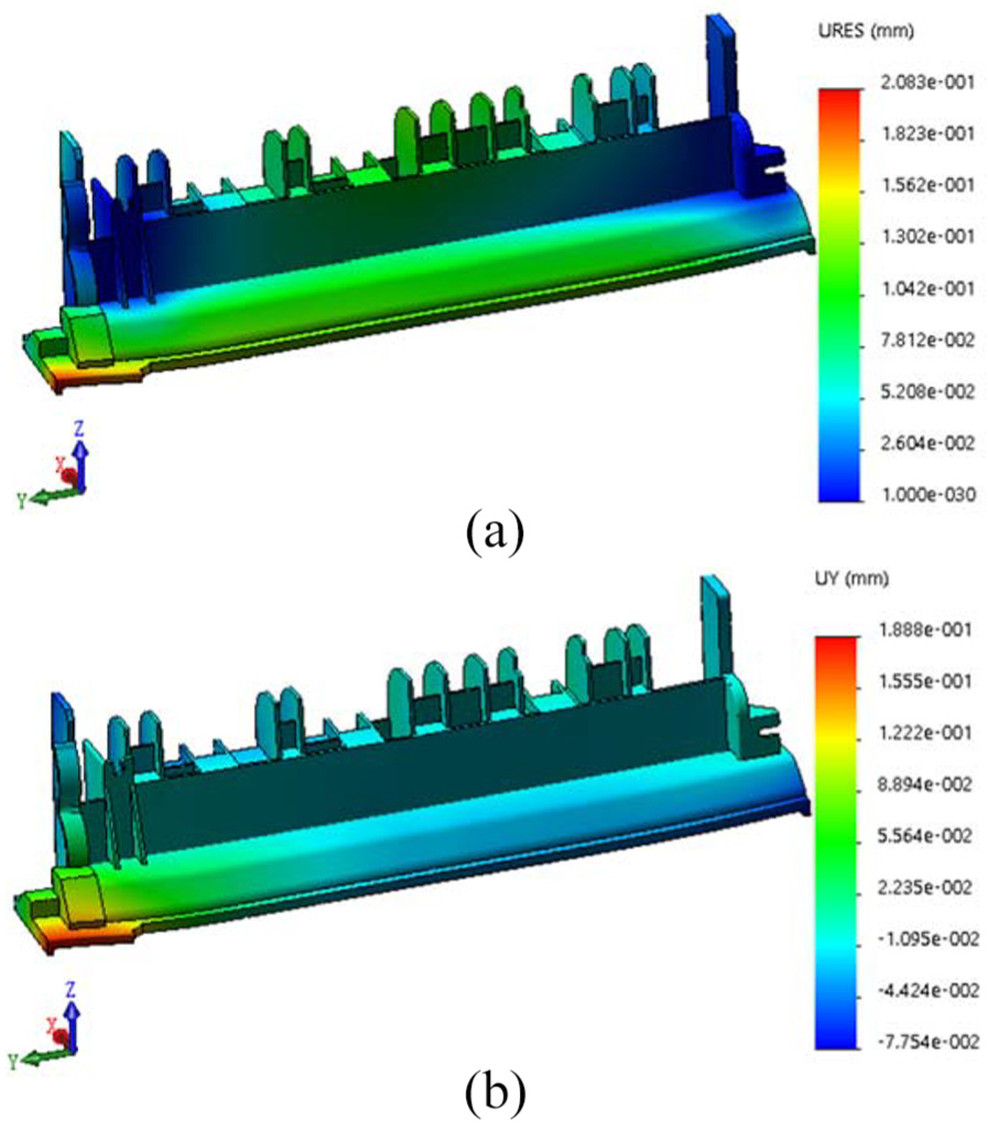
Displacement distribution of the optimized fuser upper cover: (a) resultant displacement distribution and (b) displacement distribution of Y component.
Conclusion
In this article, the importance of the fuser upper cover in the whole machine is illustrated by introducing the internal structure of a laser printer. On the basis of fusing temperature control technology of laser printer and heat exchange analysis of the whole machine, the internal steady temperature field of the laser printer is analyzed from the point of view of the whole machine. The flow trajectories and temperature distribution of the whole machine are obtained, which reflects the internal heat dissipation of the whole machine, and the temperature distribution of the fuser upper cover is further obtained. Then, the results of thermal analysis of the whole machine are applied as the external loads of static stress analysis to the fuser upper cover model so as to carry out the structural static analysis of the fuser upper cover, and the structural thermal deformation results of the fuser upper cover are obtained. The reduction of the deformation of the fuser upper cover is helpful to alleviate the problems of paper jam and angle folding. The analysis method presented in this article can be widely used to predict the deformation of parts in thermal environment, determine the allowable initial deformation of parts, so as to guide the structural optimization design of parts, adjust the production process, and improve the force mode of parts. The analysis method in this article can be used to improve the quality and efficiency of product design.
Footnotes
Handling Editor: James Baldwin
Declaration of conflicting interests
The author(s) declared no potential conflicts of interest with respect to the research, authorship, and/or publication of this article.
Funding
The author(s) disclosed receipt of the following financial support for the research, authorship, and/or publication of this article: This study is supported by the National Natural Science Foundation of China (Grant No. 51705041) and Scientific Research Foundation of the Science and Technology Department of Sichuan Province (18YYJC1705).