
Abstract
A two-dimensional nonlinear Petrov–Galerkin natural element method is presented for the large deformation analysis of elastic structures. The large deformation problem is formulated according to the linearized total Lagrangian method based on Taylor series expansion. The displacement increment is approximated with the Voronoi polygon-based Laplace interpolation functions, while the admissible virtual displacement is expanded by the constant strain basis functions that are supported on Delaunay triangles. The iterative computation is performed by Newton–Raphson method, and the numerical integration is carried out by applying the conventional Gauss quadrature rule to Delaunay triangles. The proposed nonlinear Petrov–Galerkin natural element method is illustrated through the numerical experiments, and its numerical accuracy is compared with MSC/Marc, constant strain finite element method, and Bubnov–Galerkin natural element method and the symmetry preservation in the very large strain is presented.
Keywords
Introduction
The finite element method (FEM) has been widely and successfully employed during several decades to numerically solve various engineering problems using nonoverlapping finite elements that can systematically and effectively discretize a problem domain. But, at the same time, it possesses the inherent drawbacks such as the element connectivity preservation, the numerical quality deterioration stemming from the excessive mesh distortion and the painstaking mesh adaptation. In this context, several kinds of mesh-free methods were introduced1–4 to resolve the drawbacks of FEM by substituting finite elements with grid points. These mesh-free methods provide highly smooth approximation solutions, but the subdomains are not perfectly separated and overlapped so that their basis functions do not obey the Kronecker delta property. Thus, additional techniques are required to impose the essential boundary conditions.5,6 Furthermore, these mesh-free methods need to generate additional background cells for the numerical integration using the conventional Gauss quadrature rule. What is worse, the numerical integration accuracy is influenced by how to construct the background cell.
Differing from these grid-point-based mesh-free methods, the natural element method (NEM) introduced by Braun and Sambridge
7
employs the basis functions called Laplace interpolation functions that are defined in terms of Voronoi polygons and Delaunay triangles. Since Laplace interpolation functions are defined based on the geometric relationship of Voronoi polygons, those strictly obey the Kronecker delta property.8,9 Hence, the troublesome treatment of essential boundary conditions in the conventional mesh-free methods can be completely resolved. Another important advantage of NEM is no extra effort is needed to generate background cell for the numerical integration, because Delaunay triangles that were generated for defining Laplace interpolation functions automatically serve as a background cell. In addition, like the basis functions in conventional mesh-free methods, Laplace interpolation functions exhibit the sufficiently smooth
Thanks to the abovementioned merits, the NEM has been rapidly extended to solve linear and nonlinear problems in various engineering fields.11–16 Meanwhile, the NEM may be classified into Bubanov–Galerkin and Petrov–Galerkin, depending on whether the trial and test basis functions are identical or not. In the former case, the intersection of trial and test basis function supports does not coincide with a union of Delaunay triangles, which gives rise to the numerical integration inaccuracy.17,18 This problem owing to the inconsistency between the integrand function support and the background cell can be effectively resolved by employing the test basis function that is different from Laplace interpolation function. Furthermore, in Petrov–Galerkin, the uniform Delaunay triangularization always provides the symmetric integration meshes. This symmetry at the integration mesh level guarantees the preservation of deformation symmetry, even at very large strain. Wang et al. 19 introduced a sort of Petrov–Galerkin natural element method (PG-NEM) in which the support of test basis function is identical with a Delaunay triangle. The PG-NEM leads to nonsymmetric matrices, which is an indispensable drawback to secure the numerical integration accuracy. However, nowadays it becomes a less critical issue thanks to the advances in computational facilities and technologies.
In this context, the purpose of this article is to extend a two-dimensional PG-NEM to the geometrically large deformation analysis of elastic structures. The geometric nonlinear problem is formulated according to the linearized total Lagrangian method based on the Taylor series expansion. The displacement increment is approximated by Laplace interpolation functions, while the virtual displacement is expanded by the constant strain (CS) basis functions 20 that are supported on Delaunay triangles. The numerical integration is performed by applying the conventional Gauss quadrature rule to Delaunay triangles, and the iterative computation is carried out by Newton–Raphson method. The proposed nonlinear PG-NEM is illustrated through the numerical experiments, and its numerical accuracy is verified through the comparison with MSC/Marc, constant strain FEM (CS-FEM), and Bubnov–Galerkin natural element method (BG-NEM). As well, the symmetry preservation in the deformed configuration is presented at very large strain.
Laplace interpolation functions
Figure 1(a) represents the Voronoi diagram and the Delaunay triangulation, which lay down a geometric framework for constructing a natural element grid and defining Laplace interpolation functions. For a given set
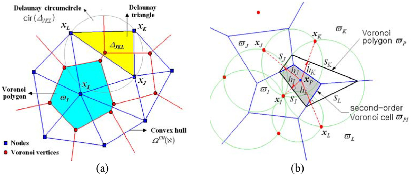
(a) Voronoi diagram and Delaunay triangulation. (b) Second-order Voronoi cells.
As a geometric dual of the Voronoi diagram, the Delaunay triangulation generates a set
To each node
With the edge lengths
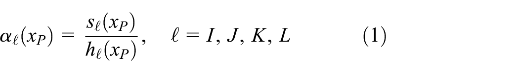
Then, the value of Laplace interpolation function
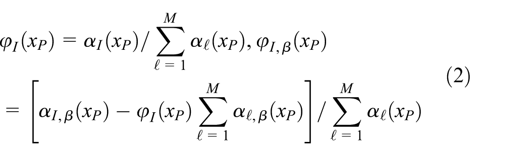
with

Laplace interpolation functions: (a) Supports. (b) Shapes.
Linearized total Lagrangian formulation
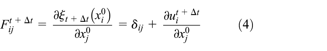
Referring to Figure 3, let us consider the geometrically nonlinear problem of a two-dimensional large deformable elastic body occupying initially an open bounded domain,

between the initial and current coordinates
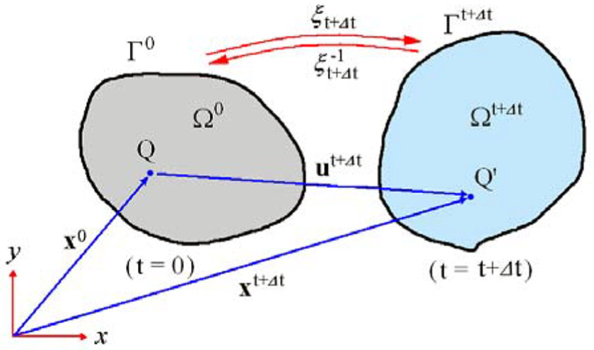
Initial and deformed configurations of a large deformable elastic body.
The deformed configuration of the body at the current time

with essential and traction boundary conditions


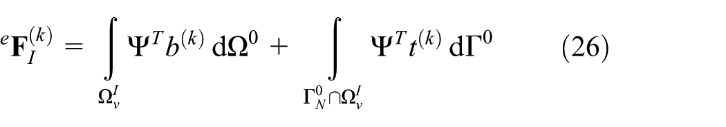
The undeformed initial configuration is taken as a reference frame using the second Piola–Kirchhoff stress

for every virtual displacement v.
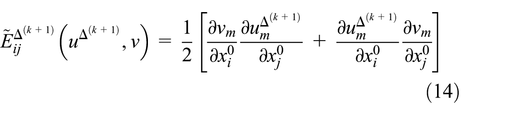
The strain-like tensor

in terms of test and trial functions v and u, and it represents the variation of the Green–Lagrange (GL) strain

The weak form equation (8) is nonlinear because

Referring to Figure 4, two superscripts

with


Schematic representation of the iterative computation scheme.
Meanwhile, according to the Taylor series expansion, the surface traction and the body force are linearized as
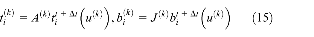
with

Elastic structures are modeled as a Kirchhoff material, which is path-independent and possess an elastic strain energy potential. The strain energy density functional and the elastic modulus tensor are as follows 21

Two-dimensional nonlinear Petrov–Galerkin natural element approximation
For the PG-NE approximation of the linearized weak form equation (16), the displacement increment


Similarly, the displacements at the kth stage (i.e. at time
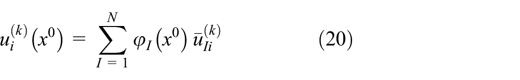

for a given natural element grid composed of N nodes. Here,

Intersection
Three shape functions

The approximation becomes the BG-NEM when both the trial and test displacements are expanded by Laplace interpolation function,
Substituting equations (18) to (21) into equation (16) leads to the matrix equations for geometrically nonlinear problems, which are given by

Here,


with
Figure 6 represents a flowchart for the large deformation analysis by the current PG-NEM, which is composed of the outer load increment loop and the inner nonlinear iteration loop. The inner iterative computation is performed by the Newton–Raphson method until the following two convergence criteria are satisfied


where,

Flowchart of the large deformation analysis.
Numerical experiments
A test program of nonlinear PG-NEM was coded according to the numerical formula given in the previous sections, and its validity and accuracy were illustrated and investigated through four representative large deformation problems. Figure 7(a) shows a cantilever beam subject to an upward vertical tip load P, where the beam is assumed to be in the plane stress condition. The length L is

(a) A cantilever beam-like structure. (b) Final deformed configurations obtained by three different methods.
The problem was also solved by BG-NEM and CS-FEM for the comparison purpose, and the total number of finite element nodes is kept the same for CS-FEM. The numerical results obtained by PG-NEM, BG-NEM, and CS-FEM are compared with the analytic solution. Figure 7(b) compares the final deformed shapes of cantilever beam, where PG-NEM and BG-NEM show almost the similar shape. But, CS-FEM leads to the remarkably different shape such that the upward deformation is much lower than that of PG-NEM. It is because the CS basis function used for CS-FEM leads to the stiffness matrix that is relatively stiffer, when compared with Laplace interpolation function. Figures 8 and 9 comparatively represent the load-deflection curves for two different NEM grids. It is clearly observed that both NEMs using Laplace interpolation function provide much better result than CS-FEM using the CS basis function. When compared with CS-FEM, NEMs provide relatively accurate results even at coarse NEM grids. Meanwhile, when compared with PG-NEM, BG-NEM leads to the slightly poor result, in particular at coarse grid. It demonstrates that the numerical integration inaccuracy of BG-NEM does also deteriorate the numerical accuracy of the large deformation analysis. However, one can find from Figure 9 that the effect of numerical integration inaccuracy becomes insignificant as the grid density increases.

Comparison of the normalized deflections (33 nodes): (a) Horizontal

Comparison of the normalized deflections (105 nodes): (a) Horizontal
The next example is an arch shown in Figure 10(a) that is subject to the tip shear traction T, where the radius r and the thickness t are 9.0 and
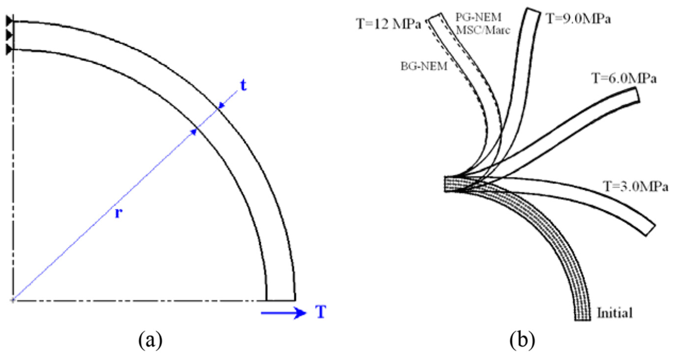
(a) An arch subject to the tip shear traction. (b) Comparison of deformed configurations (205 nodes).

Comparison of load-deflection curves (205 nodes): (a) Horizontal. (b) Vertical.
Figure 12(a) depicts a hollow half sphere subject to a uniform line traction concentrated at the top center. The uniform traction is applied on a circle, which has the conical angle
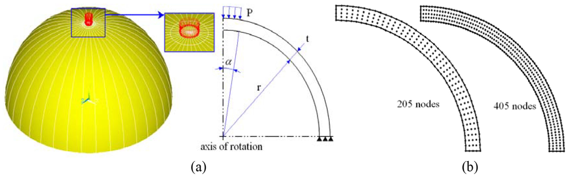
(a) A hollow half-sphere subject to circular concentrated load. (b) Natural element grids.
Figure 13(a) and (b) compares the pressure–deflection curves at the top that are obtained with 205 and 405 grid points. The comparison confirms that the PG-NEM provides the most accurate solution that is almost the same with MSC/Marc for both coarse and fine grids. However, similar to the previous cantilever problem, CS-FEM shows the remarkably poor accuracy compared with the other two methods. The deformed shapes obtained by PG-NEM at three different load steps are represented in Figure 14(a), and the final deformed shapes of all the methods are compared in Figure 14(b). One can clearly notice that PG-NEM shows an excellent agreement with MSC/Marc, but the other two methods, particularly CS-FEM, are fairly different from MSC/Marc. Thus, the accuracy of PG-NEM has been justified through three model problems, which is thanks to the fact that Laplace interpolation function provides high smoothness and the Delaunay triangle-based test function completely resolves the numerical integration error.
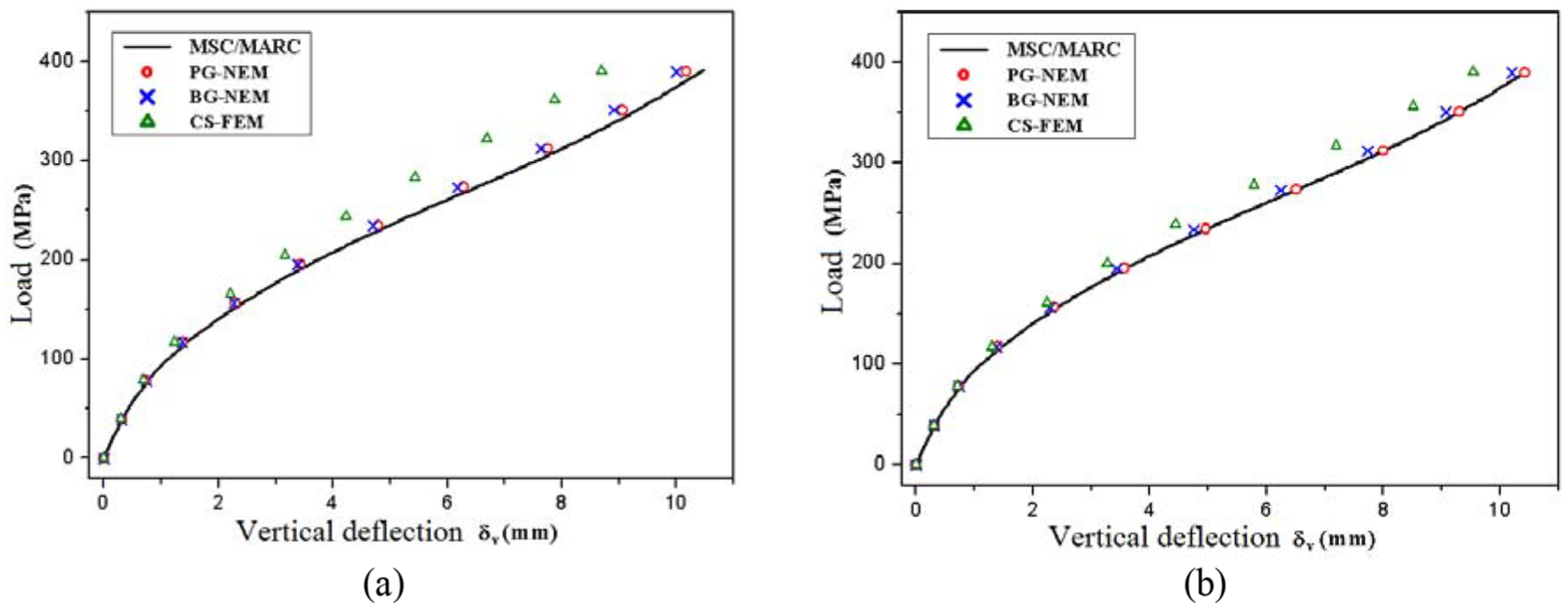
Comparison of vertical deflections: (a) 205 nodes. (b) 405 nodes.

Deformed configurations: (a) PG-NEM at different steps. (b) Comparison at the final step.
Figure 15(a) represents a two-dimensional rectangular rubber component in plane strain, which is bonded by two rigid plates on its top and bottom. This example was dealt by Calvo et al.
23
to investigate the hyperelastic neo-Hookean behavior for the rubber material by the
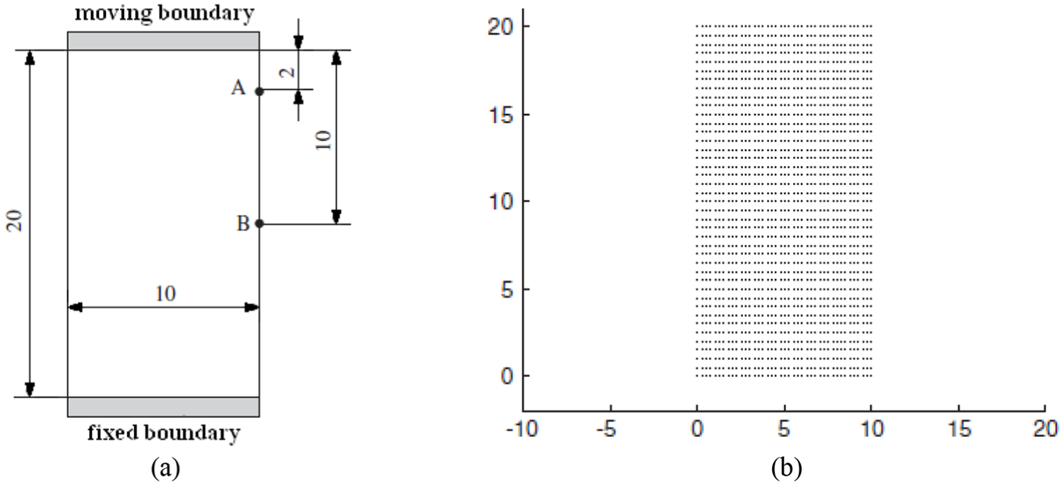
Constrained compression: (a) Rectangular rubber (unit, cm). (b) Uniform NEM grid (1681 points).
Table 1 compares the displacements at two Points A and B when the top plate is compressed by
Comparison of displacements at two points (34 load steps).
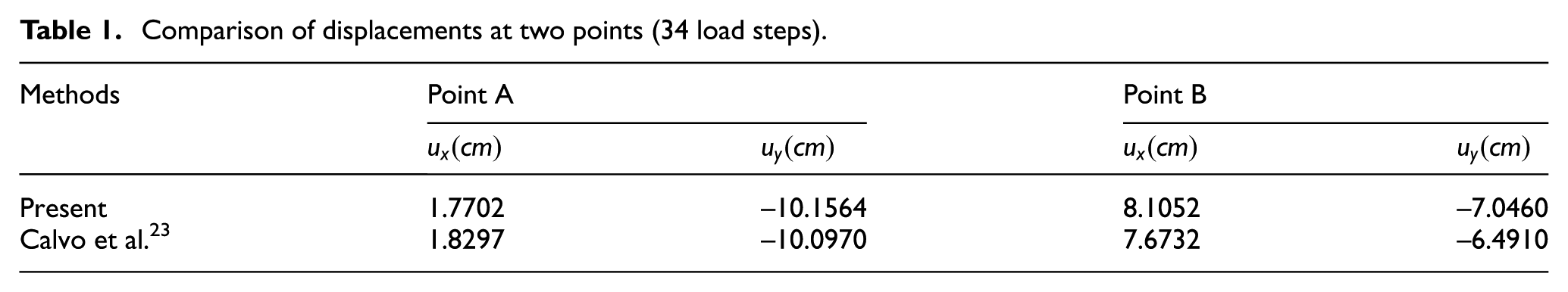
Figure 16(a) and (b) comparatively represents the deformed configuration of rubber component at the vertical compression of 10 and

Comparison of deformations at selected time steps (1681 points; unit, cm): (a) At
Figure 17 represents the displacement-reaction force curves, where the reaction forces for both nonsymmetric mesh and half model are less rigid than those of the other two, owing to the buckling effect.

Comparison of displacement-reaction force curves (1681 points).
The present method predicts less reaction forces at small compression, while it approaches the quarter model without buckling as the compression increases. The difference between the present method and the quarter model is not large with the maximum relative difference of 12%.
Conclusion
A 2-D nonlinear PG-NEM based on Voronoi polygons and Delaunay triangles has been introduced for the geometrically large deformation analysis of elastic structures. The displacement increments were formulated according to the linearized total Lagrangian method incorporated with Taylor series expansion. A combined use of Laplace interpolation functions and the Delaunay triangle–supported CS test functions provides the high smoothness and easily and accurately deals with the essential boundary condition and the numerical integration. Through the numerical experiments, the validity and accuracy of the proposed method have been verified. In particular, the proposed method provided the high interpolation accuracy even for coarse grids. On the contrary, CS-FEM and BG-NEM suffer from the numerical inaccuracy owing to the high stiffness matrix and the numerical integration error. Furthermore, the proposed method exactly preserves the symmetry in deformed configuration at very large strain. Consequently, the potential of PG-NEM for analyzing the large deformation problems has been sufficiently justified.
Footnotes
Appendix 1
Handling Editor: Daxu Zhang
Declaration of conflicting interests
The author(s) declared no potential conflicts of interest with respect to the research, authorship, and/or publication of this article.
Funding
The author(s) disclosed receipt of the following financial support for the research, authorship, and/or publication of this article: This research was supported by Basic Science Research Program through the National Research Foundation of Korea (NRF) funded by the Ministry of Education (Grant NRF-2017R1D1A1B03028879).