
Abstract
The clutch releasing finger acts as a disengagement lever and a clamping spring in the clutch, which remains in contact with the releasing bearing. Thus, the run-out of releasing fingers could result in vibrations of the clutch pedal and affect the comfort of the driver. In this article, a novel calibration mechanism is proposed for automotive clutch releasing fingers with the corresponding test bench. Based on the structural material properties, the mathematical model of the releasing fingers is developed as well as the analytical equations for the calibration force, the limit point, and the deflections. To better calibrate the run-out of the releasing fingers, the calculations of the springback and the residual curvature are also considered. Moreover, a corresponding test bench is developed, and to verify the accuracy and efficiency of the proposed method, comparisons are conducted between the novel approach and the theoretical analysis and finite element analysis methods. The results of the calibration of the run-out of the releasing fingers demonstrate the significant improvements achieved by the proposed method, which could be further applied to the calibration of various relevant elastic elements.
Keywords
Introduction
An automotive clutch connects and cuts off the power transmission of an automobile; hence its performance directly affects the load capacity, the safety, and the stability of a vehicle. In particular, the releasing fingers run-out significantly influences the noise, vibration, and harshness (NVH) response of a drive system; thus, automobile manufacturers and researchers have focused on how to reduce and test the run-out of clutch releasing fingers. For example, the clutch releasing fingers run-out is required to be controlled within 0.6 mm by NISSAN. Although several literature reports1–5 have already demonstrated testing system for automobile clutches, very few studies are available on the calibration and the test of releasing fingers.
Currently, the dial gauge and hand tool are the most commonly used method for the run-out calibration where repeated testing and measuring are required, featuring low efficiency, product consistency, and lacking quantitative results. As a result, it is imperative to develop a corresponding calibration and test system, which is based on automatic control technology to improve both the efficiency and the accuracy. A thermal calibration method is proposed in the U.S. patent, 6 however, this method is inefficient and the accuracy is vulnerable to the stability of the adjustment pressure. Moreover, the adjustment size is also not satisfying. The Germany patent 7 designed a test bench, which used an overall clamping method to measure the distance from the releasing fingers to the reference surface with a sensor. This method focused on the set-up height of the fingers and did not explicitly measure and compare the height difference of each releasing fingers.
Calibration involves basic theories related to material deformation. In recent years, innumerable efforts have been executed to predict springback as well as to develop springback-compensation tools based on finite element analysis and the analytical methods of elastic–plastic theory. Li et al. 8 calculated the calibration stroke based on the initial deflection of the workpiece to be calibrated, and established a relationship between load and deflection. MC Oliveira et al. 9 investigated the effects of material reinforcement models on springback-prediction accuracy using numerical simulations. In order to accurately predict springback, PA Eggertsen and Mattiasson 10 studied the modeling process of bending and deflection and compared the obtained results with the simulation results of five different material reinforcement models. SH Tsai and Kan, 11 the load-deflection model of a cantilever beam with a rectangular cross-section was analyzed under uniform loading conditions, and the results revealed that although the displacements of the end of the workpiece were the same for different loads, the bending contour curves were different. Urata and colleagues12,13 developed a real-time control system for seamless pipe pressure alignment based on the load-deflection model of a shaft and measured the workpiece load and deflection as well as predicted the elastic resilience. In order to eliminate errors during part measuring, a new technique was proposed in the literature 14 to compensate the inherent distortion, which occurs in the fuselage components during manufacturing. Moreover, according to the calibration guidance provided in the literature,15,16 a test bench for clutch releasing fingers calibration was designed. In order to evaluate the performance of the test bench, an analysis method named repeatability and reproducibility (R&R) 17 is also proposed whose main purpose is to quantify the fluctuation of measurement system and determine whether the equipment meets the requirements.
To achieve a higher overall efficiency and product consistency, and obtain quantitative results, a new calibration theory is proposed and a novel bench is designed based on automatic control technology in this article.
The main contributions of this study are summarized as follows: Based on plastic deformation of elastic materials, a releasing fingers’ calibration mechanism together with the FE model of releasing fingers are investigated. An automatic bench for integrated calibration and test is also designed creatively and verified by the R&R theory.
The rest of the article is organized as follows. In “Working principle of the clutch operating system” section, the function of diaphragm spring in clutch system was analyzed. Then, based on plastic deformation of elastic materials, calibration stroke of releasing fingers is calculated in “Calibration stroke calculation of releasing fingers” section. In “Deformation analysis” section, the deformation of releasing fingers is simulated and analyzed using finite element analysis method. In “Realization of calibration plan” section, an automatic bench for integrated calibration and test is proposed, which could realize calibration, test and data analysis in one time. The main structure of the bench consists of a pneumatic and hydraulic booster cylinder subassembly, a valve seat subassembly, a workpiece clamping subassembly, a releasing fingers limit subassembly, a run-out test subassembly, and a lateral clamping subassembly. The bench focuses on the innovative design of the releasing fingers calibration device, the wedge clamping limit device and the test analysis system. This bench can quantitatively display the height and run-out of the releasing fingers on the machine interface, thereby avoiding the problem in the original method which could only provide qualitative results. Moreover, the designed bench could realize the calibration and data analysis in one time, improving product consistency, reducing product rejection rate and rework rate, shortening production cycle, increasing labor productivity, and greatly reducing production cost. In “Verification” section, the feasibility of the calibration theory and method is verified by the test results and R&R theory. The results indicated that the calibration can be achieved with significantly improved accuracy and efficiency. It can be concluded that the proposed calibration theory and the designed bench are competitive.
Working principle of the clutch operating system
The releasing fingers, which act as a disengagement lever and a compression spring in the clutch, contain several incisions in the radial direction of the diaphragm spring (Figure 1). Figure 2 displays the clutch cover assembly and control system of a passenger car. At high engine speed, the clutch releasing fingers remain in direct contact with the releasing bearing, thus causing excessive run-out of the releasing bearing, consequently resulting in vibration of the clutch pedal and affecting the comfort of the driver. Therefore, it can be deduced that clutch releasing fingers run-out significantly influences the smoothness of clutch engagement as well as the comfort of the driver. As the pressure plate, the cover, and the diaphragm spring have their own tolerances during machining processes, it is difficult to meet consumer demand because clutch releasing fingers run-out occurs after assembling. Therefore, the calibration of automotive clutch releasing fingers is an important research topic for both academia and industry.
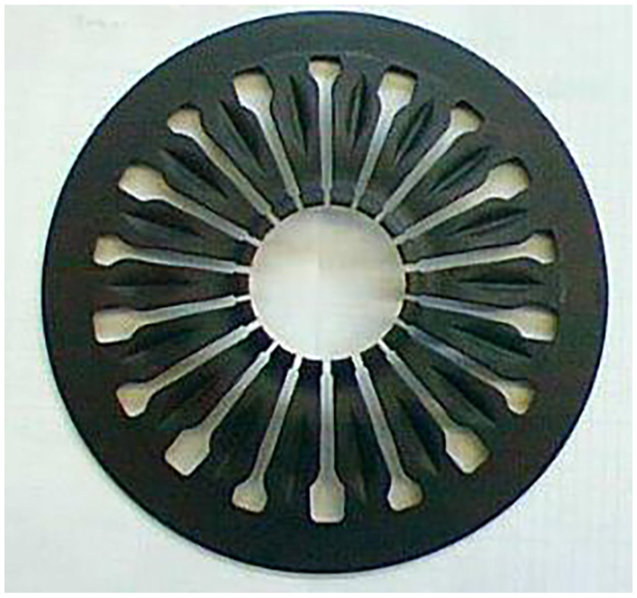
Diaphragm spring.

Clutch cover assembly and operating system.
Calibration stroke calculation of releasing fingers
Calibration principle of releasing fingers
The clutch releasing fingers deformation is considered as an elastic–plastic deformation process and can be divided into three stages: elastic, elastic–plastic, and elastic recovery.18,19
When the amount of deformation
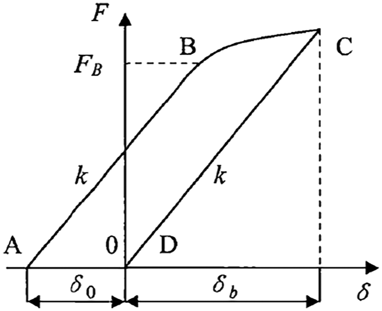
Load-deflection model.
Mathematical model of load and strain
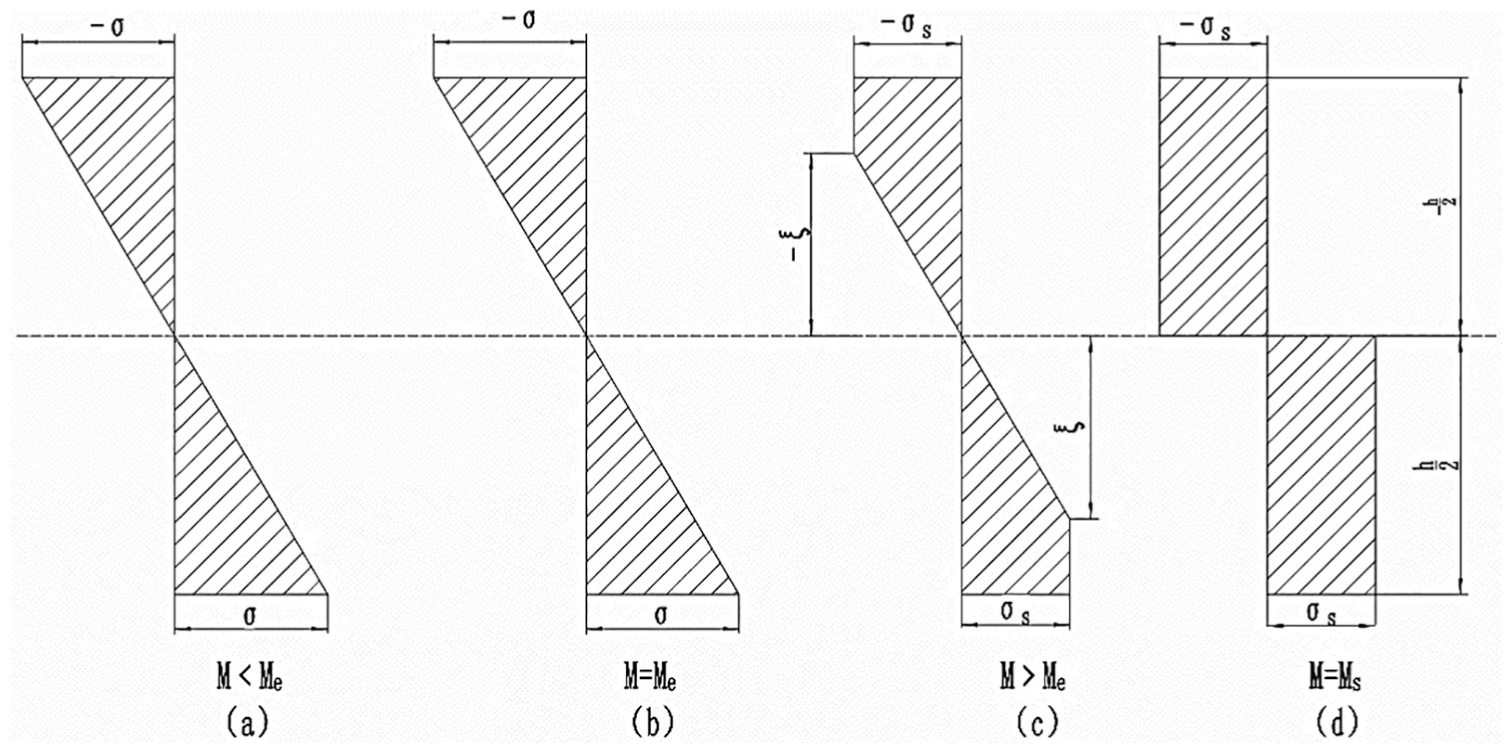
The model of the releasing fingers calibration mechanics is displayed in Figure 4. The releasing fingers are fixed at one end of the clamping assembly, the limit assembly supports the upper surface of the releasing fingers, and the screw jack exerts a deforming force on the releasing fingers. Therefore, each releasing finger can be simplified as a cantilever beam. 20

Calibrated mechanical model for releasing fingers.
Many researchers have investigated methods of beam modeling. G Chen et al. 21 proposed a general and accurate method for modeling large planar deflections of initially curved beams of uniform cross-section. However, the releasing finger of clutch is a curved compliant mechanism in nature with varied cross-sections, which should be considered. 22
In Figure 4, B is the limiting point, F is the loading force exerted by the screw jack, “a” is the distance from the clamping point to the limiting point, and L is the distance between the clamping point to and screw jack.
The beam AC consists of a simply supported beam AB and a cantilever beam BC; hence, the deformations of AB and BC will cause the total deflection at C. Therefore, the total deflection at C is the sum of the deformations of AB and BC
where L is the distance between the clamping point and applied force point, a is the distance between the clamping point and limiting point, E is the elastic modulus,
As the values of b and h are determined during product design, the amount of deformation of the releasing fingers can be changed by adjusting the parameter “a.” Moreover, the amount of elastic-limit deformation becomes smaller as the parameter a increases, and the screw jack force can also be adjusted by changing the values of a.
Elastic–plastic deformation analysis of releasing fingers
Both linear and nonlinear modeling methods have been investigated. 23 For simplicity, only linear model of releasing fingers is considered whose feasibility is proved by the test results.
1. Elastic deformation stage
The bending of the releasing fingers occurs first at the limiting point B; hence, this point yields the largest bending stress

Where

According to equation (3), the bending stress at point B reaches a maximum value when

Where
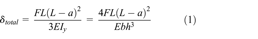
Stress distributions in the cantilever beam.
2. Elastic–plastic deformation stage
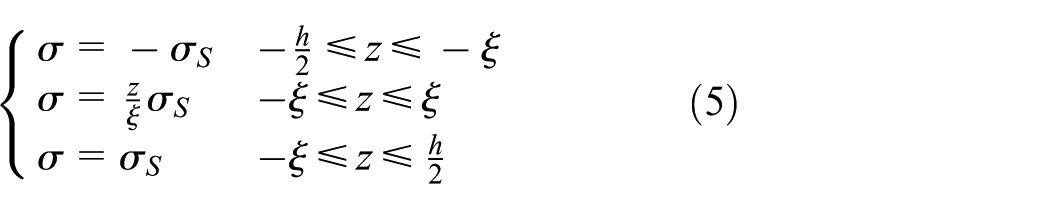
Under the application of calibration force F, the inner and the outer layers of the releasing fingers become compressed and stretched, respectively. The neutral layer is the equilibrium state between compression and stretching. In the elastic limit state, the upper and the lower surface stresses of the cantilever beam exceed the yield limit; hence, the beam starts to plastically deform. As the values of F continue to increase, the plastic area begins to expand symmetrically from top and bottom of the cross-section of the cantilever beam.
The bending moment at any section x can be expressed by the integral of normal stress of the section with respect to the neutral axis
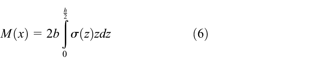
Where differential are
Therefore, the elastic–plastic bending moments of the elastic plastic coexisting sections can be obtained from equation (7)

3. Plastic deformation stage
For an ideal elastic–plastic material, the stress values at the outer fiber of the cross-section become

where
Bending springback equations of releasing fingers
The springback phenomenon usually occurs during elastic deformation or elastic–plastic deformation and can be observed in stretching and bending, straightening, and die-stamping processes; therefore, springback has profound influence on machining accuracy. 24
As the applied load increases, the degree of bending also increases, and the deformation of the workpiece changes from elastic to elastic–plastic bending. In the deformation zone of the workpiece, the inner layer becomes compressed, and the outer layer is subjected to tensile stress. When the applied bending moment M is removed from the cantilever beam, it becomes equivalent to the elastic effect caused by
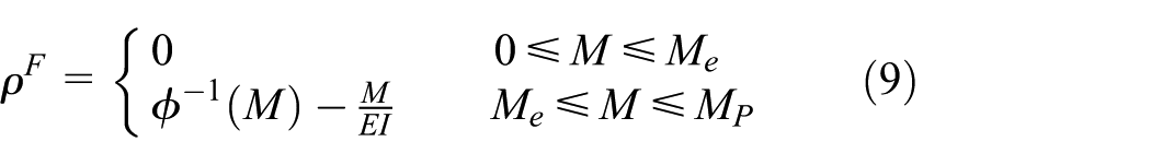
Where
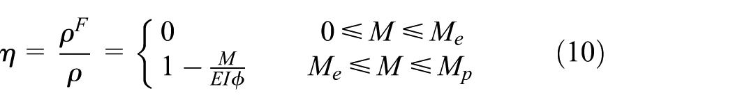
After the external load is removed, the reduction in the cantilever beam curvature is called springback, the ratio of curvatures after and before springback is termed as springback ratio
where
When the calibration force

Now, from equations (3) and (10), when

Where
The dimensionless bending moment (m) and the dimensionless curvature (ϕ) can be expressed by equation (13)

Thus, the moment–curvature relationship becomes

and its inverse function takes the form of

When
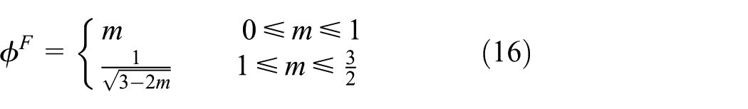

Now, by substituting equation (14) into equation (17)

Where

According to equation (19), the radius of curvature of the releasing fingers after springback
Deformation analysis
Theoretical analysis of releasing fingers deformation
The diaphragm spring parameters of the clutch releasing finger are presented in Table 1.
Diaphragm spring parameters.

Now, by substituting the above parameters in equations (1) and (4), the values of elastic limit force
When F is greater than
Now, by applying a displacement load of 2 mm to the cross-sectional area C of the clutch releasing fingers, the theoretical value of F was obtained as 740.03 N from equations (1) and (4), and compare with the result of finite element analysis value to verify the accuracy of the clutch releasing fingers bending springback equation.
Finite element analysis of releasing fingers deformation
Three-dimensional model of the diaphragm spring was established in CATIA, and then the mechanical properties of the produced model were analyzed in ANSYS Workbench. Considering the symmetrical structure of the diaphragm spring, in order to reduce the workload of the computer, only one releasing fingers was analyzed by finite element analysis. The mesh shape, number, and density have great impacts on the accuracy and efficiency of the finite element analysis. According to the structural characteristics of the releasing fingers, a sparse mesh is used for the noncritical parts of the releasing fingers, and an encrypted grid is used for the key parts of the releasing fingers, such as the limit position and the loading position. The mesh of releasing fingers is shown in Figure 6. According to the mesh independence analysis of the FE model, the tetrahedral unit is composed of 49,322 nodes and 18,756 units.
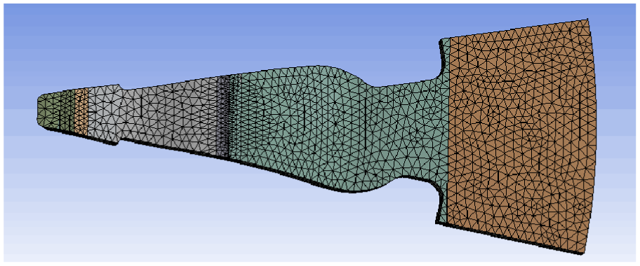
The mesh model of finger.
The material of the releasing fingers was 50 CrVA, and its properties of the bearing are presented in Table 2.
Material properties.

The restraint (fixed support) was applied to the large-end face of the releasing fingers, the frictionless support was imposed on the limit point, and the displacement load of 2 mm was applied to the point of the calibration force along the positive z axis. Figure 7 displays the deformation result of the clutch releasing fingers.

Calculation of releasing fingers deformation force.
Comparison of results
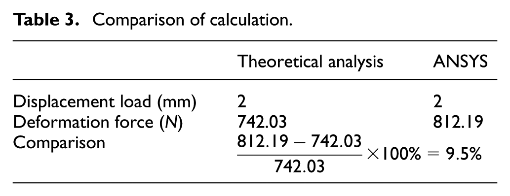
During both theoretical analysis and finite element analysis, the same displacement load was applied to the releasing fingers, and a calibration force difference of 9.5% was obtained by two methods (Table 3). It can be concluded that the simulation results are basically consistent with the theoretical calculation results.
Comparison of calculation.
Realization of calibration plan
The overall structure of the designed calibration bench is illustrated in Figure 8. The main structure of the bench consists of a pneumatic and hydraulic booster cylinder subassembly, a valve seat subassembly, a workpiece clamping subassembly, a releasing fingers limit subassembly, a run-out test subassembly, and a lateral clamping subassembly. The bench focuses on the innovative design of the releasing fingers calibration device, the wedge clamping limit device and the test analysis system. The diaphragm spring was fixed on the positioning assembly, and the pneumatic and hydraulic booster cylinder assembly was clamped with the workpiece. Sliders were used in the limit assembly according to the number of fingers in the diaphragm spring in order to limit the number of fingers at the middle of the releasing fingers. The main purpose of the limit was to provide a support for the calibration of the releasing fingers. The calibration assembly pushed the calibration head upward to apply a load to the releasing fingers in order to cause it to undergo plastic deformation. After the completion of releasing fingers calibration, the calibration assembly reset the driving calibration head, and finally, the measurement assembly was rotated by 360° to measure the height of each releasing fingers. The software automatically calculated the run-out of releasing fingers and determined whether it meets the requirements. The entire process was displayed on a human-machine interface.
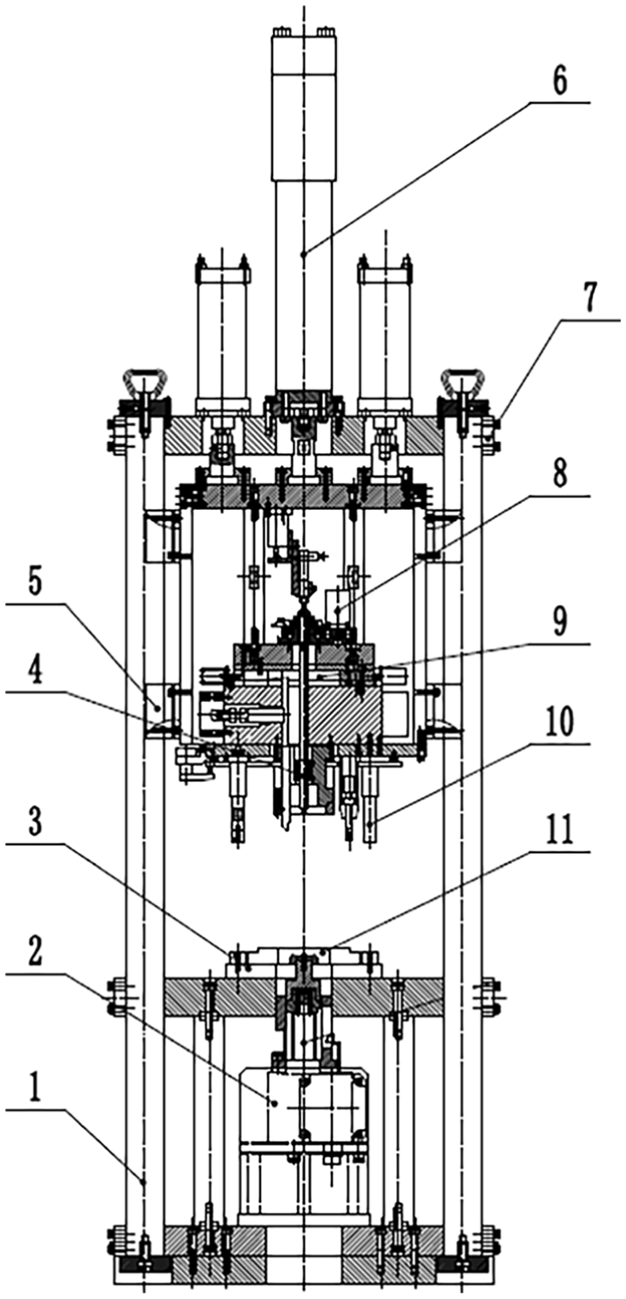
Overall structure of the test equipment.
Verification
Verification theory
The accuracy and reliability of the obtained data must be preevaluated and confirmed. Currently, the most effective tool in manufacturing to assess the quality of the measurement data and the capabilities of the measurement system is measurement systems analysis (MSA) theory. MSA refers to the comprehensive quantitative analysis of the resolution and error level of the measurement system by means of data statistics knowledge or charts to determine whether the measurement system is applicable to the measured parameters, and at the same time, make scientific judgment and evaluation on various related factors, which affect the measurement results. 26
R&R analysis is an important theory of measurement system analysis. The main purpose is to quantify the fluctuation of the measurement system and determine whether the equipment meets the requirements.
R&R is defined as

Where EV,
The R&R represents the quality of the measurement system. It is expressed as

Where “%R&R” is the ratio of equipment R&R to total variation (TV) and can be used to evaluate the acceptability of a device. In this article, the reliability of the designed bench for the run-out of releasing fingers is analyzed by R&R theory.
Test results and data analysis
The test bench is illustrated in Figure 9. The calibration interface of the bench is shown in the Figure 10. The calibration interface can clearly show the run-out and the set-up height error of clutch releasing fingers.

Test bench.

Calibration work interface and test result.
To verify whether the equipment meets the requirements, three testers (A, B, and C) were selected to examine 10 clutch cover assemblies. The tested samples were numbered from 1 to 10, which were marked in the hidden parts of the samples to meet the blind test requirements. The testers randomly measured 10 samples 3 times and collected a total of 90 data (Table 4). 27
Datasheet of releasing fingers end jumps.

The range and the average charts of the samples are illustrated in Figures 11 and 12, respectively. In both charts, the abscissa indicates part numbers. The ordinate of the average graph represents run-out height of the releasing fingers in millimeter, whereas the ordinate of the range chart denotes set-up height differences of the releasing fingers.
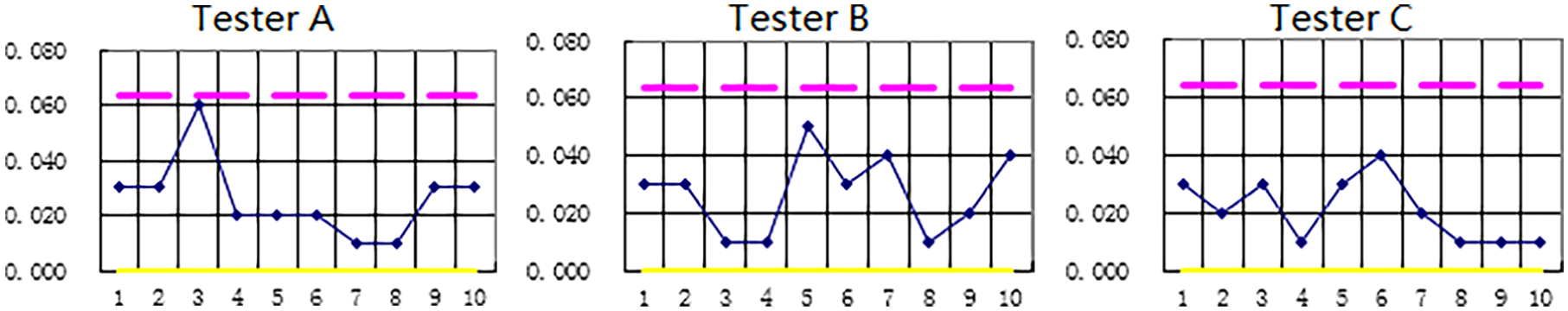
Range chart.
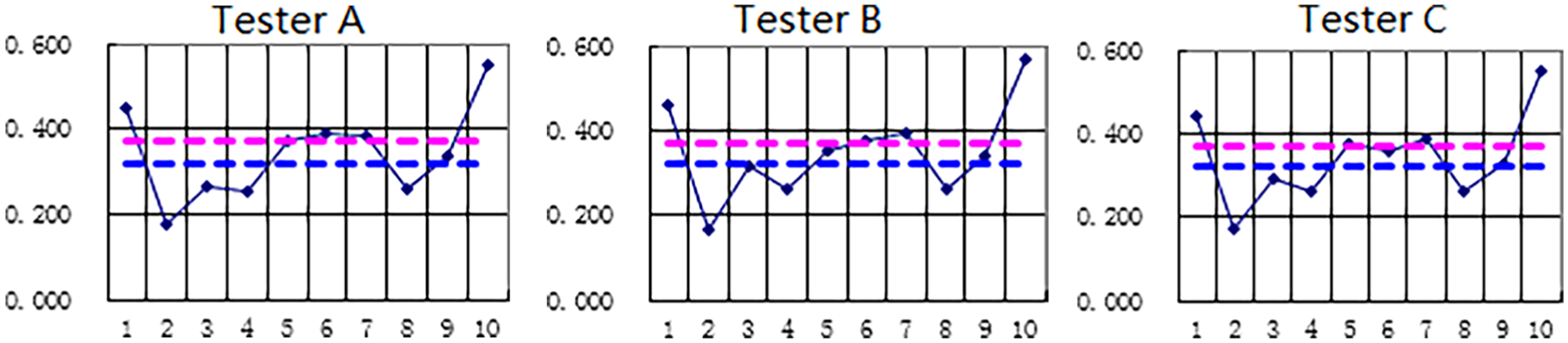
Mean value chart.
It is observable from Figure 11 that there was no point beyond the upper control limit and the lower control limit; therefore, it can be inferred that the repeatability of the designed measurement system was in a controlled state, and the skills of the evaluation staff were consistent.28–30 Moreover, most of the subgroup averages were found outside the upper and the lower control limits (Figure 12), which signifies that the deterioration of repeatability was far less than the difference between the parts; hence, the designed measurement equipment successfully meets the requirements.
The averages of the sample data measured by three evaluators A, B, and C were calculated as follows

The difference between maximum mean value and maximum value of each part was calculated as 0.007

The extreme value of each part was calculated as 0.382

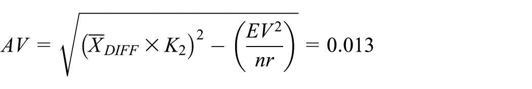
The values of equipment variation (EV) and assessment variation (AV) were measured as 0.075 and 0.013, respectively

Hence, the value of R&R was calculated as 0.076

The values of part variation (PV) and TV were calculated as 0.619 and 0.624, respectively


Therefore

According to the acceptable criteria for R&R analysis, the value of %R&R should be between 10% and 30%. 31 Therefore, the designed test bench for automotive clutch releasing finger is acceptable to meet the requirements.
Conclusion
In order to solve the existing problems of automobile clutch calibration, the current research analyzed the deformation behavior of clutch releasing fingers from the perspective of theoretical mechanics. In this article, a novel calibration mechanism is proposed for automotive clutch releasing fingers with the corresponding test bench. Based on the structural material properties, the mathematical model of the releasing fingers is developed as well as the analytical equations for the calibration force, the limit point, and the deflections. In order to verify the accuracy of the proposed calibration mechanism, a certain type of clutch releasing fingers is considered as an example and compared with the obtained results using theoretical analysis and finite element analysis method. Finally, a clutch releasing fingers test bench is designed according to the proposed calibration mechanism. The results of the calibration of the run-out of the releasing fingers demonstrate the significant improvements achieved by the proposed method, which could be further applied to the calibration of various relevant elastic elements.
Footnotes
Handling Editor: Shahin Khoddam
Declaration of conflicting interests
The author(s) declared no potential conflicts of interest with respect to the research, authorship, and/or publication of this article.
Funding
The author(s) disclosed receipt of the following financial support for the research, authorship, and/or publication of this article: This research is supported by the State Scholarship Fund of China Scholarship Council (201706695018).