
Abstract
In the process of manufacturing and operation of mechanical equipment, accurate measurement of vector force provides an important basis for real-time control of working conditions and process adjustment to ensure the performance. Piezoelectric three-component force unit can be used to measure three-axis force with the characteristics of high frequency and stiffness, great dynamic response, and resistance to harsh conditions. Piezoelectric dynamometer consisting of four three-component force units can measure six-axis force/torque, which is widely used in vector force measurement. However, because of the limitation of manufacturing capability and assembly process, dimension coupling caused by assembly error of three-component force unit restricts improvement of test accuracy for itself and piezoelectric dynamometer. To reduce dimension coupling caused by displacement and angle assembly error, this article establishes a theoretical model of assembly error of three-component force unit. To achieve that the dimension coupling of three-component force unit is less than 3%, stiffness of relevant components is obtained by simulation analysis and experiment, and assembly tolerance range of three-component force unit is proposed. Four three-component force units are assembled to meet assembly tolerance range, and the calibration experiment is performed. The results show that the maximum of dimension coupling is less than 2.5%, which verifies the rationality of assembly tolerance range and further proves the reliability of the theoretical model. The theoretical model of assembly error clarifies the assembly accuracy of three-component force unit to ensure its test accuracy, which can further improve test accuracy of dynamometer. This article will also provide theoretical reference basis for this kind of sensors.
Introduction
Heavy-load equipment has the characteristics of heavy loading, large inertia, multi-degree of freedom, and multi-dimensional loading.1–3 Sensing and measurement is an important part of the control system for heavy-load equipment. With the development of heavy loading equipment for manufacturing and advanced equipment for test, accurate measurement of vector force determines device control coordination and force adaptability in equipment operation, which is essential for real-time control of working conditions and process adjustment.4,5 Six-axis force/torque sensor can be used to measure forces Fx, Fy, and Fz and torques Mx, My, and Mz in Cartesian coordinate system simultaneously, which is widely used in vector force measurement of heavy-duty equipment, especially for the free forging machine, hydraulic die-forging press, and heavy grasping manipulator. However, dimension coupling of six-axis force/torque sensor caused by the factors, such as compact structure, manufacturing error, and assembly error, limits the improvement of test accuracy.6,7
At present, the measuring principles of six-axis force/torque sensor mainly include strain and piezoelectric type. To solve the problem of structure coupling and error coupling of strain sensors, some researches have been performed. Cao et al. 8 analyzed the structural coupling and assembly error coupling of strain six-axis force/torque sensor, and a linear decoupling method was designed to improve decoupling precision. To reduce dimension coupling caused by manufacturing and assembly error of Stewart platform, Hou et al. 9 designed a novel six-axis force/torque sensor structure and presented the parameter optimization of sensor structure with genetic algorithms (GAs). Zeng 10 proposed the P normative decoupling network which is applied to compute decoupling matrix to reduce dimension coupling of six-axis force sensor caused by the integrated structure. Wang et al. 11 developed an optimal design for a fully preloaded six-axis force/torque sensor, and the calibration matrix was used to eliminate coupling. Fu and Song 12 adopted the back-propagation (BP) decoupling algorithm optimized by GA to improve the measurement precision of six-axis force/torque sensor for robot, and the decoupling results validated the good decoupling performance. To reduce coupling error, Ma et al. 13 proposed a novel nonlinear static decoupling algorithm based on the establishment of a coupling error model, and the calibration results showed the high decoupling accuracy.
Strain six-axis force/torque sensors, with the characteristic of high accuracy, are mainly suitable for static or quasi-static measurement because of the disadvantages, such as slow measuring speed, unstable circuit, and complicated decoupling. Compared to strain six-axis force/torque sensors, piezoelectric six-axis force/torque sensors with high stiffness, high sensitivity, high natural frequency, and excellent dynamic characteristics are suitable for static and dynamic vector force measurement.14–16
Piezoelectric six-axis force/torque sensors generally adopt multi-point support combined measuring structure, and dimension coupling is an important factor limiting the test accuracy. To improve the test accuracy of piezoelectric six-axis force/torque sensors, some articles have researched dimension coupling. Based on least-squares support vector machine regression, Li et al. 17 proposed a fusion decoupling algorithm to optimize multi-dimensional nonlinear characteristics of sensor outputs, and the coupling error was reduced. Liu et al. 18 proposed a decoupling matrix for the piezoelectric six-axis heavy force/torque sensor, and the coupling error was reduced to 3% applying the decoupling matrix. Qin et al. 19 designed a parallel piezoelectric six-axis force/torque sensor with eight piezoelectric quartz crystal cells, and the results of calibration experiment showed that the coupling error was within 4%. Zhang et al. 20 analyzed the experiment data of piezoelectric six-axis force/torque sensor, and the coupling equation was obtained to decouple calibration data. Liu et al. 21 researched different arrangements of the piezoelectric quartz crystals about the coupling error and designed a piezoelectric six-axis force/torque sensor. The experiment results showed that coupling error of circle arrangement was less than 3% after applying the decoupling matrix. Li et al. 22 proposed the decoupling algorithm based on radial basis function (RBF) neural network to reduce the dimension coupling error of a four-point supporting piezoelectric six-axis force sensor. Huang et al. 23 designed a decoupling method to provide an alternative tool for the reliability-based design optimization problems. Li et al. 24 applied the generalized inverse static decoupling algorithm based on the solution matrix of calibration matrix to reduce dimension coupling of three-axis force sensor with four supporting points, and the largest coefficient was less than 3%.
The dimension coupling of piezoelectric six-axis force/torque sensor is mainly affected by structure design, assembly error, and layout type. All the above-mentioned articles are based on decoupling algorithms and structural designs, and few articles consider the influence of assembly error on dimension coupling. Piezoelectric dynamometer, with four-point supporting type, consists of four three-component force units in parallel. The dimension coupling of piezoelectric dynamometer is affected by three-component force unit which can be used to measure three-axis force. To reduce the dimension coupling of piezoelectric dynamometer and improve its test accuracy, it is generally required that the measurement sensitivity of four three-component force units is approximately the same, 25 and the dimension coupling is less than 5%. However, while assembling the three-component force unit, it is necessary to apply a large preloaded force, which is easy to bring about displacement and angle errors of sensor causing dimension coupling. Therefore, the influence of sensor assembly error on test accuracy of three-component force unit cannot be ignored.
To reduce the dimension coupling of three-component force unit caused by assembly error of sensor, this article researches the influence of assembly error on dimension coupling. Taking displacement and angle assembly error of sensor into consideration, theoretical model of assembly error of three-component force unit is established, which proposes different assembly accuracy requirements for three-component force unit corresponding to different test accuracy. The three-directional stiffness of upper plate, sensor, and preloaded bolt is obtained by the simulation combining experiment. To achieve that the dimension coupling of three-component force unit is less than 3%, the assembly tolerance range is proposed by the theoretical model of assembly error combined with the stiffness of relevant components. Four three-component force units are assembled, which meet the assembly tolerance range, and the calibration experiment is performed. The calibration results show that dimension coupling of four three-component force units is less than 3%, which proves the rationality of the theoretical model.
Theoretical model of assembly error
Structure of three-component force unit
Piezoelectric dynamometer consisting of four square-arranged three-component force units in parallel is shown in Figure 1(a). Based on the piezoelectric effect, it can be used to measure six-axis force/torque. As a core component of piezoelectric dynamometer, the three-component force unit is mainly composed of upper plate, sensor, lower plate, preloaded bolt, and preloaded nut, which can be used to measure three-axis force, as shown in Figure 1(b). Taking the three-component force unit with the size of 55 × 55 × 60 mm3 as an example, the material is stainless steel (1Cr18NiMoV), which has the characteristics of anti-rust and anti-magnetic, and the frequency can reach up to 200 kHz. Wherein, preloaded bolt is screwed with lower plate and preloaded nut, and the sensor keeps intimate contact with the upper and lower plate under preloaded force. There is a clearance between sensor and preloaded bolt, as shown in Figure 1(c). The preloaded force in axial direction is realized by preloaded nut, which generates a frictional force to limit displacement and rotation of sensor.

Structure of piezoelectric dynamometer: (a) piezoelectric dynamometer, (b) piezoelectric three-component force unit, and (c) sensor and preloaded bolt.
Theoretical model of assembly error of sensor
While three-component force unit is loaded by vector force, there is a load sharing among the relevant components, and the three-directional stiffness of each component is the main reason for the influence of load sharing. Because of the clearance between sensor and preloaded bolt, the displacement and angle assembly error of sensor will change direction and action point of theoretical vector force, and the piezoelectric wafer will be unevenly stressed, resulting in the generation of dimension coupling. To reduce the dimension coupling caused by assembly error, the assembly accuracy requirements should be proposed by establishing the theoretical model of assembly error. It is assumed that there is no error in the process of quartz crystal wafer cutting and assembly. θ is the angle error between upper plate and sensor, wherein the clockwise is positive; Δx and Δy are the displacement errors of geometric center between sensor and preloaded bolt in X and Y directions, respectively; a is the axial height of the upper plate; and h is the axial height of the sensor. The theoretical model of assembly error in X and Y directions of three-component force unit is shown in Figure 2. XOY is central coordinate system of upper plate, X′O′Y′ is actual assembly coordinate system of sensor, and X″O″Y″ is theoretical assembly coordinate system of sensor.
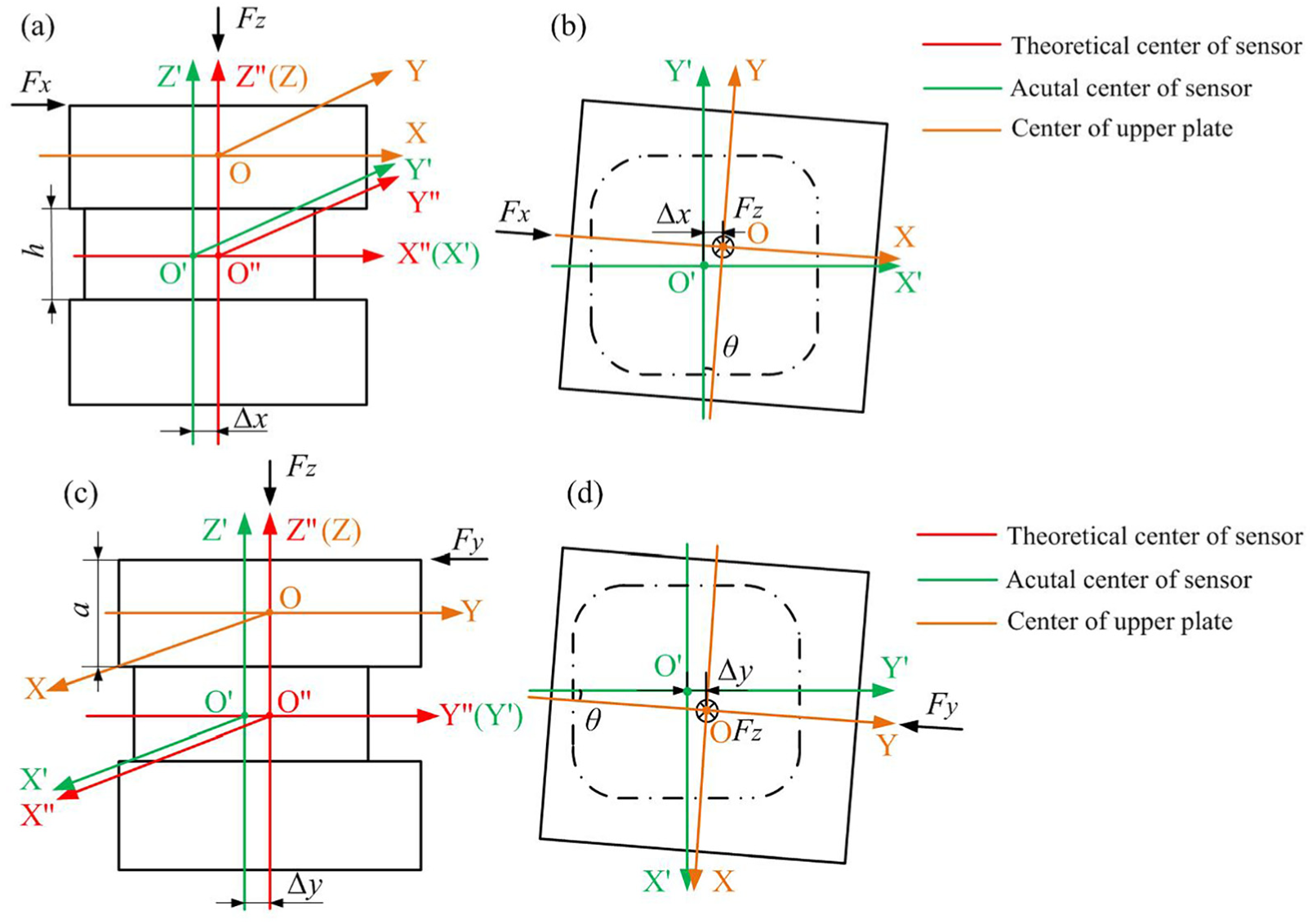
Theoretical model of assembly error of three-component force unit: (a) front view of assembly error model in X-direction; (b) top view of assembly error model in X-direction; (c) front view of assembly error model in Y-direction; and (d) top view of assembly error model in Y-direction.
1. Dimension coupling in Z-direction caused by lateral loading force under assembly error model (
While three-component force unit is loaded by the lateral force


where d is the diameter of upper circular surface of the sensor, which is connected with upper plate;

where

where

where

Through equations (4), (5), and (2), equation (7) is obtained as follows
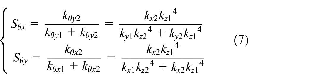
The dimension coupling in Z-direction caused by the lateral force

2. Dimension coupling in X and Y directions caused by lateral force under assembly error model (
Based on the piezoelectric effect, the lateral force

3. Dimension coupling in X and Y directions caused by main force under assembly error model (
While three-component force unit is loaded by main force
Assembly tolerance range
The theoretical model of assembly error proposes different assembly accuracy requirements for three-component force unit corresponding to different test accuracy. Because the three-directional stiffness is involved in the theoretical model, the method of simulation combining experiment is used to measure the three-directional stiffness of upper plate, sensor, and preloaded bolt. To achieve that the dimension coupling of three-component force unit is less than 3%, the assembly tolerance range is proposed by the theoretical model of assembly error combined with the stiffness of relevant components. The assembly precision is clarified by assembly tolerance range. Namely, if the assembly accuracy of three-component force unit meets assembly tolerance range, the dimension coupling will be less than 3%.
Stiffness measurement
Three-directional stiffness of upper plate, sensor, and preloaded bolt is obtained by simulation combining experiment to calculate allowable assembly error range of three-component force unit. As the loading force increases, the deformation of relevant components increases. The ratio of the force value to the deformation is the stiffness value. Because the structure of upper plate and preloaded bolt is relatively regular, three-direction stiffness can be obtained by simulation analysis. However, the internal structure of sensor is generally complicated, and the method of simulation cannot accurately calculate its deformation. Through the loading force experiment, three-directional deformation of sensor is measured by inductive length measuring instrument so that the three-directional stiffness can be calculated accurately.
1. Three-directional stiffness of upper plate and preloaded bolt
In static analysis of ANSYS, upper plate and preloaded bolt are both stainless steel (1Cr18NiMoV) materials, and the preloaded force of preloaded bolt in Z-direction is set to 28,000 N. The directional deformation of upper plate and preloaded bolt under step loading forces of 400, 800, 1200, 1600, and 2000 N in X and Y directions is obtained as shown in Figure 3(a)–(d), and the directional deformation of upper plate and preloaded bolt under step loading forces of 1000, 2000, 3000, 4000, and 5000 N in Z-direction is obtained as shown in Figure 3(e) and (f). Fitting curves of deformation with step loading forces are shown in Figure 4, and the ratio of force value to the deformation is stiffness. Through the directional loading force, the directional deformation of upper plate and preloaded bolt is obtained. As the loading force increases, the deformation of upper plate and preloaded bolt increases. Due to the symmetry of the structure, the deformation in X and Y directions of upper plate and preloaded bolt is approximately equal, separately. And the fitting curves show the good linearity of simulation data.

Directional deformation of upper plate and preloaded bolt with step force: (a) deformation of upper plate in X-direction; (b) deformation of preloaded bolt in X-direction; (c) deformation of upper plate in Y-direction; (d) deformation of preloaded bolt in Y-direction; (e) deformation of upper plate in Z-direction; and (f) deformation of preloaded bolt in Z-direction.

Three-directional stiffness fitting curves of upper plate and preloaded bolt: (a) fitting curves of upper plate in X and Y directions; (b) fitting curves of preloaded bolt in X and Y directions; and (c) fitting curves of upper plate and preloaded bolt in Z-direction.
2. Three-directional stiffness of sensor
Due to the complex internal structure of sensor, three-directional stiffness of sensor obtained by simulation analysis will exit a large error. The step loading force experiment is performed in X-, Y-, and Z-direction of three-component force unit by standard force sensor, and directional deformation of sensor is measured by inductive length measuring instrument to calculate three-directional stiffness of sensor accurately. During the measurement of sensor stiffness in Z-direction, two inductive sensors are, respectively, placed on the lower surface of upper plate and the upper surface of lower plate for difference measurement. During the measurement of sensor stiffness in X- and Y-direction, an inductive sensor is placed on the side of sensor to directly measure deformation. Sensor deformation test system is mainly composed of loading block, pedestal, force loading device, data acquisition (Data Translation DT9804), inductive length measuring instrument (DGS-6 C), computer, and software, as shown in Figure 5. Inductive length measuring instrument is adjusted to the second gear with a measurement range of −100 to +100 µm and a resolution of 0.1 µm. Vector force generated by force loading device is loaded on the loading block. Standard force sensor transmits force signal through data acquisition and computer software. Step loading forces acting on three-component force unit in Z-direction are set to 1000, 2000, 3000, 4000, and 5000 N, and the corresponding data of inductive length measuring instrument are recorded. Step loading forces acting on three-component force unit in X and Y directions are set to 400, 800, 1200, 1400, and 1600 N, and the corresponding data of inductive length measuring instrument are recorded. To ensure the stability and repeatability of the data, the experiment is repeated four times, and the average value is obtained for linear fitting to calculate three-directional stiffness of sensor. The linear fitting results are shown in Figure 6. As the directional loading force increases, the directional deformation of sensor increases. The linearity of the fitting curves obtained by the experiment is lower than that of simulation because of the measurement error. The stiffness of sensor obtained by experiment and the stiffness of upper plate and preloaded bolt obtained by simulation have the same magnitude, which proves that the methods of simulation and experiment both have certain rationality.

Directional deformation measurement of sensor in X-, Y-, and Z-direction.
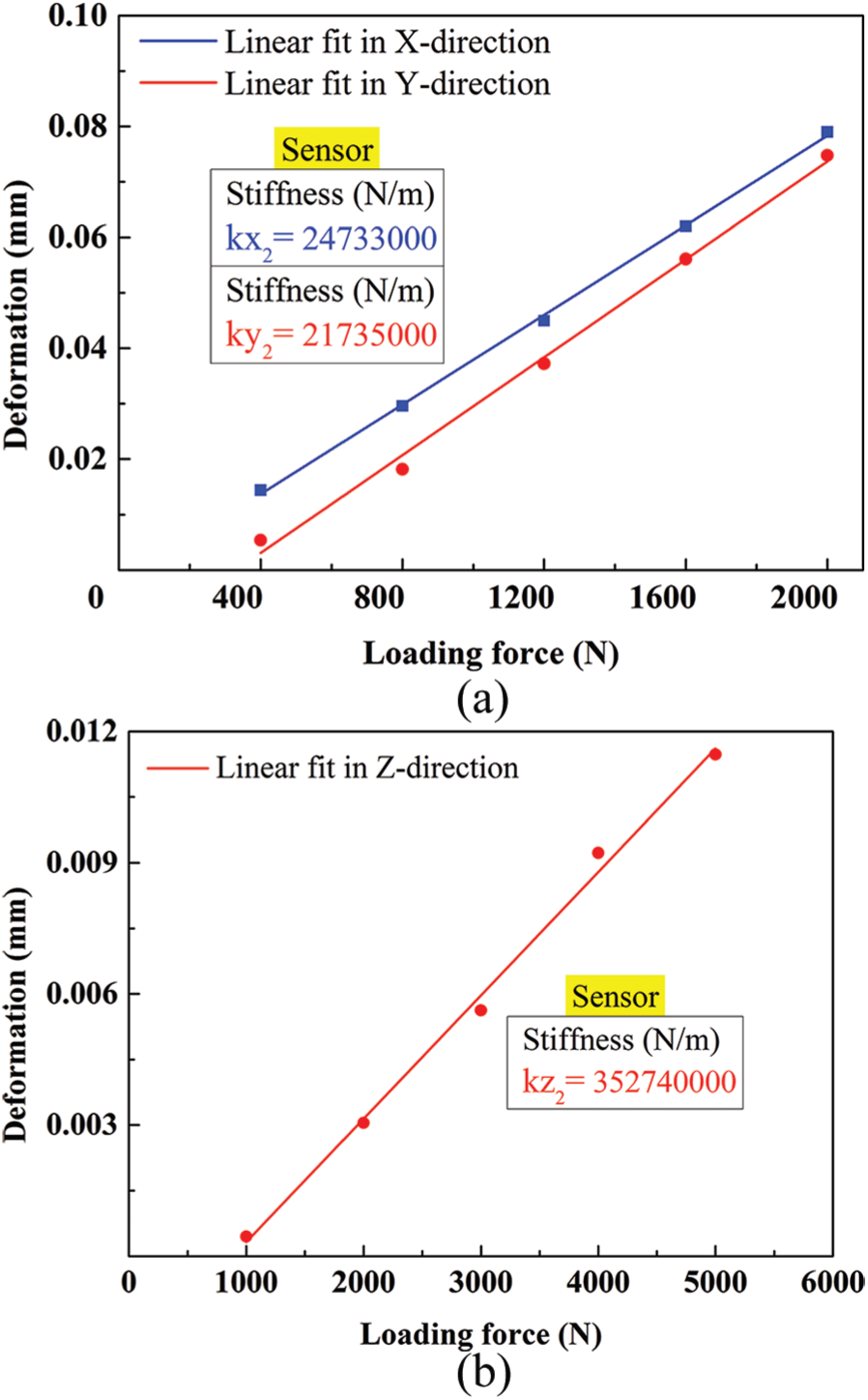
Three-directional stiffness fitting curves of sensor: (a) fitting curves of sensor in X- and Y-direction; (b) fitting curve of sensor in Z-direction.
Assembly tolerance range
Through the simulation analysis and the deformation measurement experiment, three-directional stiffness of plate, sensor, and preloaded bolt is obtained. Because of the large magnitude of stiffness, in order to simplify calculation, scientific notation is used to retain three significant figures, as shown in Table 1.
Three-directional stiffness of upper plate, sensor, and preloaded bolt.

The dimensional coupling of three-component force unit directly affects the test accuracy of piezoelectric dynamometer. To achieve high-precision test of six-axis force/torque for large heavy-duty equipment, the dimensional coupling of three-component force unit is required to be less than 5%. To achieve that the dimension coupling of three-component force unit is less than 3%, three-directional stiffness of upper plate, sensor, and preloaded bolt is substituted into formulas (7)–(9) to obtain assembly error tolerance range of sensor in X, Y, and Z directions, and the assembly precision of three-component force unit is clarified.
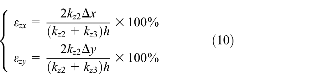
To ensure that the dimensional coupling in Z-direction caused by lateral force

To ensure that the dimensional coupling in Y-direction (X-direction) caused by the lateral force

To ensure that the dimensional coupling in X and Y directions caused by the main force

Experiments
To verify the rationality of assembly tolerance range, four three-component force units are assembled through assembly device, and assembly error is measured by relevant tools. After meeting requirements of the assembly tolerance range, three-directional force calibration experiment of four three-component force unit is performed. The calibration results are analyzed, which proves the reliability of assembly tolerance range.
Measurement of assembly error of three-component force unit
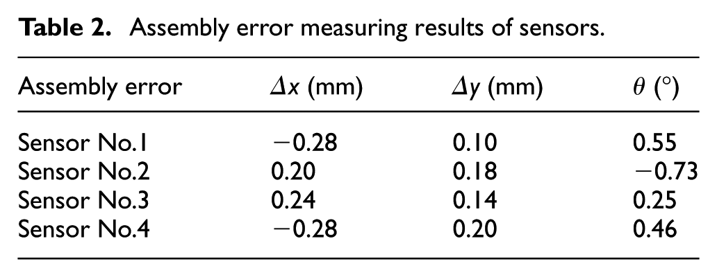
The assembly error of three-component force unit is measured using dial indicator with precision of 1 μm and micrometer with precision of 0.01 mm, as shown in Figure 7. To measure angle assembly error of sensor relative to upper plate, each three-component force unit is placed on ultra-clean platform so that the side of lower plate is attached to ultra-clean plane. Taking that side of lower plate as a basis, five points on the side of upper plate and sensor are, respectively, selected, and the height is measured by dial indicator. The measurement is repeated three times, and average value is obtained. The slope is calculated by least-squares method, and angle deviation is obtained by inverse trigonometric function, where clockwise angle deviation is determined to be a positive value. After that, the side of upper plate is attached to ultra-clean plane. Taking that side of upper plate as a basis, three points on the side of sensor are selected, and the depth is measured by micrometer. The measurement is repeated three times, and average value is obtained. Through the difference of three sets of average depth corresponding points, the displacement assembly error of sensor in X and Y directions is obtained, and the measuring results of assembly error are shown in Table 2, which shows that assembly error of four three-component force units meets the requirements of assembly tolerance range.

Assembly error measurement of sensor.
Assembly error measuring results of sensors.
Calibration experiments
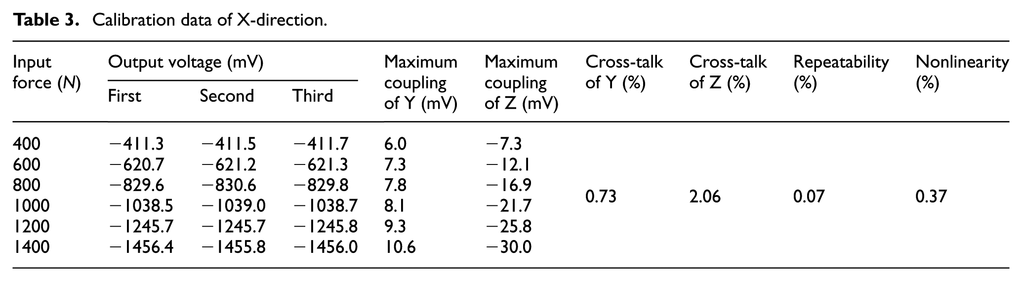
Four three-component force units, which meet assembly tolerance range, are subjected to calibration experiment. The calibration system is mainly composed of calibration device, charge amplifier (Sinocera Piezotronics LN5861), data acquisition (Data Translation DT9804), computer, and software, as shown in Figure 8. The three-dimensional orthogonal calibration experiment of three-component force unit is performed. According to step-by-step loading method, standard force sensor with the range of 5000 N is adopted in Z-direction, and standard force sensor with the range of 2000 N is adopted in X and Y directions. The main loading step force is set to 500, 1000, 2000, 3000, 4000, and 5000 N, and the lateral loading step force is set to 400, 600, 800, 1000, 1200, and 1400 N. To ensure the stability and repeatability of the data, the loading experiment is repeated three times in each direction. To match the output voltage and the loading force, the charge amplifier sensitivity of X and Y directions is set to 8.00 pC/N, and Z-direction charge amplifier sensitivity is set to 4.00 pC/N. The calibration experiment data in X, Y, and Z directions of the No.1 three-component force unit are shown in Tables 3–5, respectively.

Calibration experiment of three-component force unit.
Calibration data of X-direction.
Calibration data of Y-direction.

Calibration data of Z-direction.
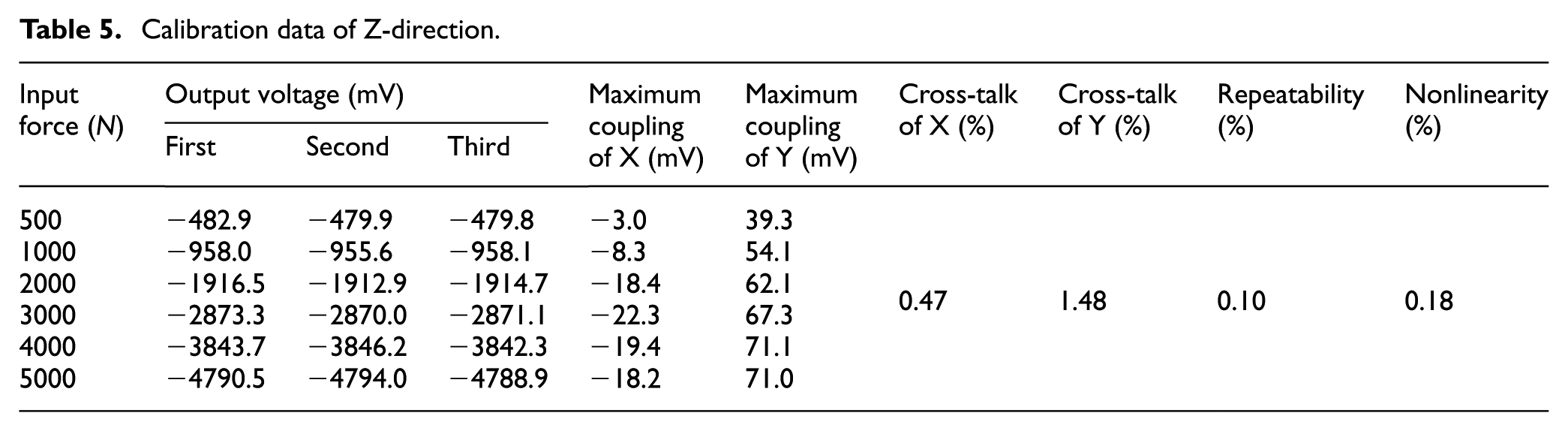
It can be seen from Tables 3–5 that the three-directional output of the No.1 three-component force unit has great linearity and repeatability, and the maximum dimension coupling is only 2.40%. The maximum dimension coupling of No.2, No.3, and No.4 three-component force unit is 2.36%, 2.30%, and 1.41%, respectively, which are all lower than 2.5%. The repeatability of No.2, No.3, and No.4 three-component force unit is less than 0.2%, and the nonlinearity is less than 0.4%. The calibration results verify the rationality of assembly tolerance, which further proves the reliability of theoretical model.
Conclusion
The dimensional coupling of three-component force unit affects its testing accuracy, which in turn affects the test accuracy of piezoelectric dynamometer. Taking displacement and angle assembly error of sensor into consideration, the theoretical model of assembly error of three-component force unit is established, and the theoretical expression of dimensional coupling caused by assembly error is obtained. To achieve that the dimension coupling of three-component force unit is less than 3%, assembly tolerance range of three-component force unit is proposed. Four three-component force units are assembled to meet assembly tolerance range, and the calibration experiment is performed. The results verify the rationality of assembly tolerance range and further prove the reliability of theoretical model. The theoretical model of assembly error proposed in this article is suitable to reducing the dimension coupling caused by assembly error of three-component force unit with different specifications through improving the assembly accuracy. The theoretical model of assembly error clarifies the assembly accuracy of three-component force unit corresponding to different test accuracy, and further improves the testing accuracy of dynamometer, which is essential for real-time control and process adjustment of heavy-load equipment.
Footnotes
Handling Editor: Jixiang Yang
Declaration of conflicting interests
The author(s) declared no potential conflicts of interest with respect to the research, authorship, and/or publication of this article.
Funding
The author(s) disclosed receipt of the following financial support for the research, authorship, and/or publication of this article: This project was supported by the National Natural Science Foundation of China (grant nos 51475078 and 51675084) and the Aeronautical Science Foundation of China (grant no. 20160163001).