
Abstract
Two-stroke engines taking advantages of high power density and light weight as well as small size are widely used on aircrafts. Compared with conventional fuel injection system, gasoline direct injection technology can control the air-fuel ratio according to different working conditions and thus a more efficient combustion can be achieved. Normally, a solenoid valve is employed in the gasoline fuel injectors to control the injected fuel amount and timing. In this study, the performance of a novel voice coil motor for gasoline direct injection injectors of a two-stroke aviation engine is studied. The voice coil motor works as a linear actuator to pressurize the fuel, and thus the amount of injected fuel and the injection timing can be controlled by the driving current of the coil. As a result, the high-pressure pump of the conventional fuel injection system can be canceled. The working principle of the voice coil motor is described at first. Then, a finite element model of the voice coil motor is setup, and the influences of structure parameters including the coil turns, the magnetizer height, and the yoke thickness are analyzed. Subsequently, the magnetic equivalent circuit methodology is used to study the response characteristics of the voice coil motor. The results show that the coil turns, the magnetizer height, and the yoke thickness are three important parameters that will influence the electromagnetic force. The total mass and resistance of the coil and the coefficients k and ke are four important parameters that will influence the dynamic response time. A theoretical optimization of these parameters can improve the system performance of the voice coil motor significantly. The results of this study can provide a reference for the design of gasoline direct injection system for aviation piston engines.
Keywords
Introduction
Two-stroke engines take advantages of high specific power, compactness, light weight, and low cost, which make it popular in aviation crafts. However, because of mixture scavenging, which leads to fuel short-circuiting and excessive exhaust emissions, 1 people are trying to replace the conventional fuel injection system with gasoline direct injection (GDI) to reduce fuel consumption and CO2 emission and to improve engine power output. 2 The GDI fuel injection system sprays fuel directly into the combustion chamber with a high injection pressure, resulting in a good atomization and evaporation process,3,4 which have been widely used in automobiles. However, the normal GDI system has a complex structure which is not good for an aviation piston engine. The long high-pressure fuel path increases the risk of gasoline leakage and is not beneficial for the reliability and safety. To address this challenge, ROTAX Co., Ltd. developed a GDI injector with a high-speed voice coil motor (VCM) for a two-stroke aviation engine (ROTAX800). In this novel injection system, the VCM functions as a linear actuator and is integrated into the injector. The high-pressure fuel pump of the normal GDI injection system is canceled and the high-pressure fuel path is shortened significantly. However, it is critical to find a good design and optimization method for this type of VCM.
Many investigations have been performed to improve the performance of VCM for various applications. Goto et al. 5 proposed a surface permanent magnet arrangement (CSPM arrangement) with a magnetic flux concentration type, which could generate a high magnetic flux density in the air gap between the stator and the rotor. Chi et al. 6 pointed out that the internal vertical peak flux density was reduced greatly via improving the structure design of the magnet and the back iron of a VCM. Encica et al. 7 proposed a spacing mapping technique to optimize the magnetic loop of a cylindrical VCM. Xu and Chang 8 developed a tubular moving-coil linear machine using quasi-Halbach magnet. Liu et al. 9 studied the effects of the parameters of the magnetic circuit on the static electromagnetic force. The performance of VCMs has been improved significantly with the progress of technology. A study showed that the vibration of the high-speed VCM could be controlled. 10 A very high frequency can be achieved and a working fluid with a high volumetric density can be employed. 11 Teo et al. 12 proposed a new structure for a VCM with a force-current ratio of 60 N/A. Kim et al.13,14 developed two different types of VCM with a high force density for an electromagnetic actuator.
The magnetic flux density of a VCM can be increased by Halbach array permanent magnet, and thus a more rapid transient response can be achieved.15–20 The Halbach magnetized permanent magnet array has a hollow rotor structure. Therefore, a machine with a very low rotational inertia can be implemented. The acceleration performance of the coil rotor can be improved. An investigation showed that the dynamic force of the VCM can be increased by 11%. 21 However, the decreased magnetic saturation limit and the increased complexity of the structure and the manufacturing process constraint the industrial applications. Rare-earth permanent magnets with Halbach array have a high induction and coercive force, 22 allowing the electrons in the alloy structure to align with each other anisotropically and obtain a very high residual induction with a high resistance against being demagnetized (or the intrinsic coercivity). 23
Besides the physical model design, the optimization of the control algorithm of VCM is also very important.24,25 VCM is a kind of drive servo system and the control strategy should have a good robust performance against external disturbances. Lin and Li 26 proposed a dynamic sliding-mode fuzzy control method for the trajectory tracking control of a VCM. Taktak-Meziou et al. 27 studied a nonlinear model predictive control for a single-stage VCM used in the hard disk drive. Seok and Kim 28 designed a disturbance decoupling strategy to reject the disturbance and improve the tracking performance. Yang et al. 29 applied a robust back-stepping control approach to the Stewart platform to solve the active vibration isolation problem.
The heat dissipation of VCM is another important issue. During the high-frequency working process, the VCM can generate a lot of heat. Finite element method and computational fluid dynamics method can be used for the thermal analysis of the motor. 30 The heat generated inside the permanent magnet synchronous motor normally includes copper, iron, and mechanical loss. 31 Dorrell 32 performed a coupled thermal-magnetic analysis of an induction motor using a modern design software package, showing it is an effective method. Both Davin et al. 33 and Lim and Kim 34 investigated the influence of the fuel flow speed, the inlet temperature, and the geometry on the cooling efficiency of the motors.
The VCM works as a linear actuator to establish a high pressure inside the fuel injector. Compared with the conventional fuel injection system, the high-pressure pump and the common rail are canceled. Therefore, the long high-pressure fuel path is shortened significantly and the whole fuel injection system is simplified. The cost of the system is reduced and the reliability is improved. In this study, the performance of a VCM used in the GDI injector for ROTAX800 engine is studied. The main parameters that have great impacts on the electromagnetic force and the dynamic response characteristics are analyzed and optimized. First, the structure and working principle of the VCM are presented. Then, a finite element model (FEM) method is adopted to analyze the influences of the main dimensional parameters on the electromagnetic characteristics of the VCM. Subsequently, the dynamic response characteristic of the VCM is analyzed using a magnetic equivalent circuit (MEC) method. The analysis results are validated by the experimental data. The electromagnetic force and the dynamic response time of the designed VCM can be improved significantly via this theoretical optimization. The results of this study are helpful for the optimization and development of new injection system for aviation piston engines used in small general aircrafts.
System description
Injector with a VCM
The main structure of a traditional GDI solenoid-actuated injector is shown in Figure 1. The coil is fixed together with the iron core while the armature moves up and down. If no current inside the coil, the spring force imposed on the armature pushes the needle against the seat and no fuel is sprayed. When the coil is energized, the electromagnetic force pulls the armature upward and the spring is compressed. The high-pressure fuel enters into the injector and the needle is lifted by a hydraulic force. Accordingly, the high-pressure fuel is injected through the holes at the tip of the injector. This traditional design suffers a low dynamic response characteristic owing to a large mass of the armature and the needle. In addition, the high-pressure fuel (>30 MPa) must be supplied. Therefore, the traditional GDI system has a complex layout. A long high-pressure fuel path with a high-pressure pump is required. Such a long high-pressure fuel path increases the weight of the aviation engine and is not helpful for the improvement of the work-to-weight ratio. Furthermore, the risk of gasoline leakage is high, yielding a low reliability and safety. To address this challenge, the GDI injector with a VCM for a two-stroke aviation engine is investigated in this study.
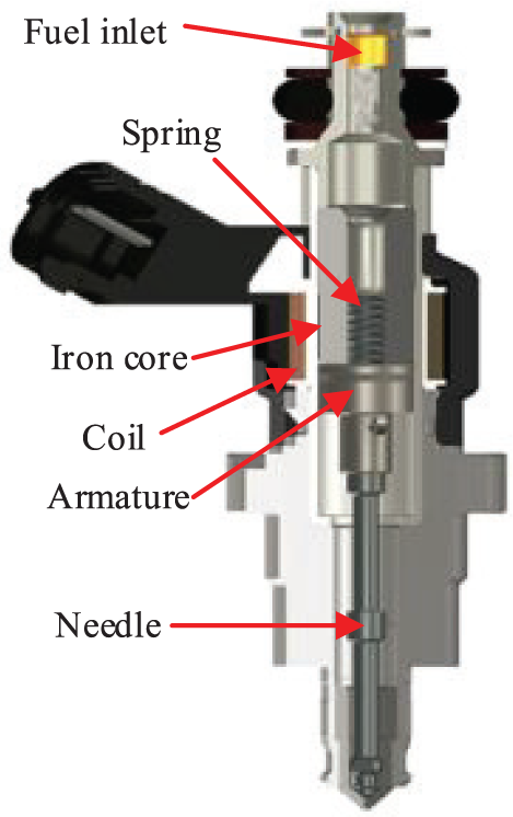
Structure of a typical GDI solenoid-actuated injector.
The fuel injection system using the injector with a VCM is shown in Figure 2. A fuel pump delivers the low-pressure gasoline fuel directly to the inlet of the injector. When the coil of the VCM is energized, it pushes the plunger to compress the gasoline fuel. Eventually, the high-pressure fuel is injected into the cylinder. Because neither the high-pressure pump nor the common rail is installed, the high-pressure path of the fuel system can be shortened significantly. As a result, the fuel injection system can have a simple structure.
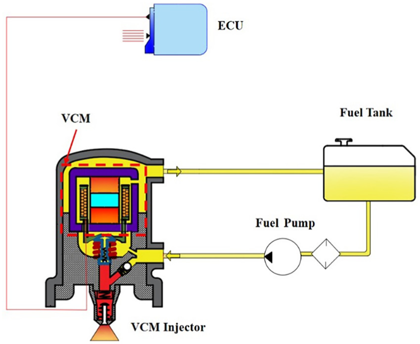
Fuel injection system using an injector with a VCM.
A prototype of the VCM integrated with the injector is shown in Figure 3. Figure 4 shows a 2D schematic. The injector mainly consists of a magnetic yoke, two permanent magnets, a magnetizer, a coil and its support, a reset spring, a plunger, a one-way valve, a needle, and a ball valve. The coil is installed between the magnetic yoke and the permanent magnets. The coil support is connected with the coil rigidly. The magnetizer is inserted between the upper and the lower permanent magnets. The coil is concentric with the centerline of the magnetizer and moves up and down when the current is excited. The linear motion of the coil is guided by the contact cylindrical surface between the coil and the magnets. The guide design must be good enough without any parasitic motion to give an accurate control of the injected fuel amount. The movement direction of the coil is controlled by the direction of current.

Photo of the VCM prototype.

Structure of the fuel injector with a VCM: 1, yoke; 2, fuel return orifice; 3, coil; 4, coil support; 5, reset spring; 6, plunger; 7, upper permanent magnet; 8, magnetizer; 9, lower permanent magnet; 10, chamber A1; 11, one-way valve; 12, needle; 13, chamber A2; 14, ball valve.
A current will be generated in the coil if a voltage is imposed on the coil. Accordingly, an electromagnetic force is imposed on the coil owing to the magnetic field of the two permanent magnets. Then, the coil support overcomes the spring force and the fuel damping force, pushes the plunger moving toward the accumulator chamber A1. As a result, the fuel pressure inside the chamber A1 rises until the one-way valve overcomes the spring force. With the one-way valve open and the plunger moving forward, the fuel pressure in the accumulator chamber A2 also increases. Finally, the fuel pressure imposed on the needle exceeds the limit and the needle moves backward, resulting in the injection of the high-pressure fuel into the cylinder.
When the current direction of the coil is reversed, the direction of the electromagnetic force imposed on the coil is changed and the plunger moves back. Accordingly, the pressure inside the chamber A2 decreases and the needle closes the injection hole. As the plunger continues backward, the ball valve will open if the pressure inside the chamber A1 is less than a certain value. The fuel from the low-pressure pump flows into the accumulator chamber A1. On the other hand, the return fuel flow is used to lubricate and cool the coil. The hole in the center of the coil support is open once the plunger moves forward. Part of the fuel flows into the VCM and then out via the fuel return orifice. As a result, the coil will be lubricated and cooled. The coil is energized only part of the working time during one engine cycle (less than 1/3) and the generated heat is not serious. A large part of the heat is dissipated via the contacting surface to the magnets and then to the engine block. Therefore, only a small part of heat is brought away by the fuel. The fuel flow rate is normally a few percentages of the total delivery fuel amount by the low-pressure fuel pump.
In this design, the coil instead of the magnets is used as the mover because the mass of the coil is less than that of the permanent magnets. Therefore, the response time is shorter, which is very important for the injection process under a high engine speed. As seen in Figure 3, one end of the coil wire is embedded in the coil support and the other end is embedded in the shell of the injector. Because the coil moves forward and backward with a high speed and the structure of the injector is complex, special attention and engineering design should be paid to the arrangement of these two end connections of the coil wire.
Driving of the VCM
The fuel injector with a VCM is controlled by an electronic control unit (ECU). The driving principle of the injector is shown in Figure 5. The microprocessor of the ECU receives several analog signals from different sensors measuring the engine speed, the throttle position, the coolant temperature, the intake air pressure and temperature, the lambda signal, and the knock signal. Then, these signals are sampled and several maps are used to calculate the injected fuel quantity according to the current working condition of the engine. Finally, the driving pulse width modulation (PWM) signal is determined based on the demanded fuel quantity and injection timing.

Electronic control unit for driving the injector with a VCM.
The rotating speed of a gasoline engine can be up to 8000 r/min, requiring a fast dynamic response of the VCM. The microprocessor controls the frequency and the duty cycle of the driving PWM signals. The direction signals are also output to control the current direction of the coil. A full-bridge circuit is adopted to drive the VCM. The driving chip LTE6284G with four MOSFETs is used. The operation modes are illuminated by Figure 6. The current will be generated in the coil if a voltage is imposed on the coil via controlling the on/off state of these four MOSFETs. Figure 6(a) shows the positive current applied to the VCM by setting the two MOSFETs on. The electromagnetic force imposed on the coil is positive and the plunger moves forward. When the current direction is reversed by setting the other two MOSFETs on (see Figure 6(c)), the direction of the electromagnetic force imposed on the coil is changed and the plunger moves back. Short circuit should be avoided during the current switching process. Therefore, two other modes shown as Figure 6(b) and (d) are inserted to produce a dead time signal. The duration of the PWM signal is controlled according to the demand of the injected fuel quantity, which is encoded as a 2D feedforward map based on the engine speed and the throttle position in the software.

Operation modes of the full-bridge driving circuit (M represents the coil): (a) mode with positive driving current; (b) mode for switching from positive to negative; (c) mode with negative driving current; (d) mode for switching from negative to positive.
FEM
FEM is a common method for the electromagnetic field simulation. The software Maxwell (version 2015.1) is used in this study. It is developed by the ANSYS company and employed by many researchers, which has a high accuracy and a user-friendly interface.35–37 First, a 3D model of the VCM is built for the FEM analysis shown in Figure 7(a). The VCM is mainly composed of five parts: the yoke, the upper magnet, the magnetizer, the coil, and the lower magnet. The magnetizer is used to guide the magnetic induction lines through the coil. The upper permanent magnet is arranged to make the magnetic lines go downward, while the magnetic lines of the lower permanent magnet is upward.

Schematic of the VCM: (a) magnetic induction lines; (b) main dimensional parameters.
The basic Maxwell equations for the magnetic field are represented by


where H (x, y, z) is the magnetic field strength, B (x, y, z) is the magnetic induction intensity, and J (x, y, z) is the current density.
In this study, the material of the magnet is configured as NdFe35 in the software Maxwell with a relative permeability of 1.09978 and a coercive force of 890000 A/m2. In practice, the type of the NdFeB material is N38SH. The magnetizer is assembled between the upper and lower permanent magnets to guide the magnetic induction lines of the permanent magnets and to provide a sliding surface for the coil. The material of the magnetizer is pure iron and is specified as Steel-1010 in the software Maxwell. The material of the external magnet yoke is carbon steel (AISI 1010). The yoke is used to constraint the magnetic induction lines and protect the inner coil.
Influences of dimensional parameters
The dimensional parameters of the VCM have a great effect on the electromagnetic force of the coil. A good performance can be achieved via optimizing these parameters appropriately. In this section, the main parameters of the VCM including the coil turns, the magnetizer height, and the yoke thickness are analyzed based on the FEM method.
Coil turns
The energized coil pushes or pulls the plunger to control the injection process of the high-pressure fuel. The electromagnetic force generated by the coil is proportional to the coil turns N approximately. Therefore, the influence of the coil turns on the performance of the VCM is analyzed at first. According to the mechanical constraints, the maximum outer diameter and the height of the coil are set to 36 mm and 14 mm, respectively.
To study the influence of the coil turns, 10 different cases for the parameters of the coil are specified. The detailed parameters are listed in Table 1. The wire inner diameter is the diameter of the naked copper wire. The wire outer diameter is the outer diameter of the enameled wire. Because the diameters of the coil wire for each case are not the same, the coil resistance does not increase linearly as the coil height increases. The driving current is fixed at 12 A. The magnetic flux density is not constant around the magnets and the coil. For each different case, the effective length and the effective number of the coil turns could be changed. Therefore, the electromagnetic force is computed by the FEM model using the ANSYS Maxwell. The FEM model calculates the electromagnetic force for each cell inside the coil based on the local magnetic flux density, and then an overall integrated value over all the cells is determined. The simulated results for the electromagnetic force are also listed in Table 1. The electromagnetic force of the coil increases with the increase of the coil turns. However, the size and weight of the VCM also rises. The transient response of the coil will be degraded if the weight of the coil is too large. It can be seen that the electromagnetic forces for the cases 8, 9, and 10 are greater than 110 N. Therefore, case 8 is chosen for the following analysis. The corresponding detailed parameters of the VCM are listed in Table 2, which are labeled in Figure 7(b). The final value for the coil turns is 150. The inner and outer diameters of the copper wire are 0.4 and 0.44 mm, respectively. The height of the coil is 12 mm. The estimated electromagnetic force is 113.25 N with a resistance of 2.07 Ω.
Results for different parameter sets of the VCM.
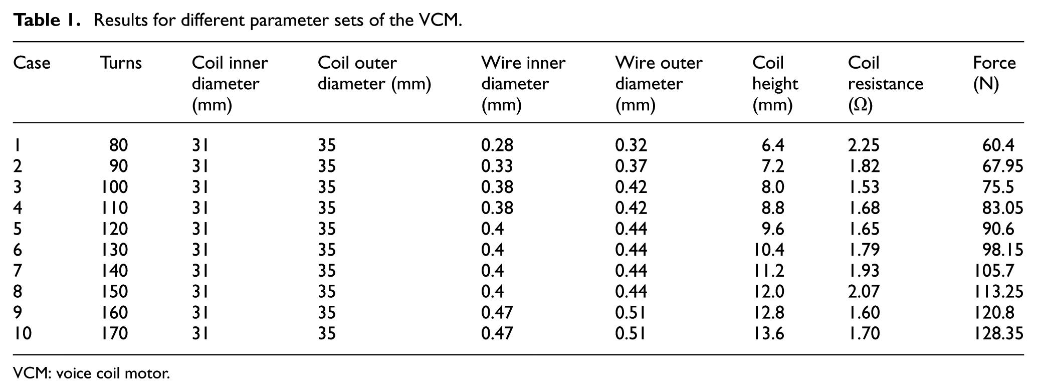
VCM: voice coil motor.
Parameters for the FEM analysis of the VCM.

FEM: finite element model; VCM: voice coil motor.
Magnetizer height
After the coil turns are specified, the variation of the magnetizer height and the yoke thickness is evaluated. In this study, the total height of the two magnets and the magnetizer is set to a fixed value of 22 mm (labeled as PH in Figure 7(b)). Nine different values of the magnetizer height are taken into account (i.e. 8, 7, 6, 5, 4, 3, 2, 1, 0 mm). The corresponding heights for each of the magnets are 7, 7.5, 8, 8.5, 9, 9.5, 10, 10.5, 11 mm. On the other hand, six different values for the thickness of the yoke are taken into account (i.e. 1, 2, 3, 4, 5, 6 mm). The current is fixed at 12 A. The other parameters of the VCM are the same as Table 2. The FEM model setup in the above section is used to estimate the electromagnetic force and the energy loss of the VCM.
First, the electromagnetic force of the coil is calculated when the magnetizer height and the yoke thickness vary. The driving current of the coil is fixed at 12 A and a 3D surface of the results is shown in Figure 8(a). The corresponding contour map is shown in Figure 8(b). It can be seen that the electromagnetic force of the coil first increases and then decreases as the magnetizer height ascends from 0 to 8 mm. On the other hand, the electromagnetic force basically increases as the yoke thickness rises from 1 to 6 mm. When the magnetizer height is in the range of 1 and 6 mm and the yoke thickness is between 3 and 6 mm, the electromagnetic force is in the peak region. The detailed data are listed in Table 3.

The electromagnetic force as a function of the magnetizer height and the yoke thickness with a driving current of 12 A: (a) 3D surface; (b) contour view.
Results of the electromagnetic force with various magnetizer height and yoke thickness.

MT: magnetizer height; YT: yoke thickness.
Second, the influence of the magnetizer height with different driving currents is analyzed. The results are shown in Figure 9. The thickness of the yoke is fixed at 4 mm. It can be seen that the force first increases rapidly and then decreases slightly. The force is greater than 110 N when the height of the magnetizer ranges from 1 to 6 mm, reaching the maximum of 113.25 N with a magnetizer height of 3 mm. However, if the height of the magnetizer is less than 1 mm, the electromagnetic force drops evidently to 94.34 N, showing a great influence of the magnetizer height on the performance of the VCM. Furthermore, the electromagnetic force increases almost linearly with the increase of the driving current, which can be explained by equation (7) with no magnetic saturation occurrence. 35

Results of the electromagnetic force versus the magnetizer height for different driving currents.
The width of the air gap is set to 5 mm in this study. If this dimension is too large, the magnetic induction intensity of the air gap will drop. If it is too small, the friction loss of the coil will increase. The influence of the magnetizer height on the magnetic induction intensity in the air gap is analyzed and the results are shown in Figure 10. The driving current is set to 12 A. The magnetizer height is set to 0, 3, and 8 mm. It can be seen that the maximum magnetic induction intensity arrives to 0.858, 1.136, and 0.916 T, respectively. The electromagnetic force of the coil is proportional to the magnetic induction intensity. In other words, the greater the magnetic induction intensity, the greater the electromagnetic force of the coil. Therefore, the magnetizer height is set as 3 mm. The corresponding maximum magnetic induction intensity is 1.136 T.

Influence of the magnetizer height MT on the magnetic induction intensity inside the air gap: (a) MT = 0; (b) MT = 3 mm; (c) MT = 8 mm.
Figure 11 gives the vector distribution of the magnetic flux density inside the entire VCM including the magnets, the magnetizer, the coil, and the yoke for the three different magnetizer heights, showing that the magnetizer height has a great influence on the magnetic induction intensity. The maximum magnetic induction intensity is located at the middle of the magnetizer wall as 8.19 T with a magnetizer height of 3 mm, followed by a maximum magnetic induction intensity of 2.19 T when the height of the magnetizer is 8 mm. The maximum magnetic induction intensity is 1.85 T, where the height of the magnetizer is 0, indicating the distribution of the magnetic induction lines is very poor without the magnetizer.
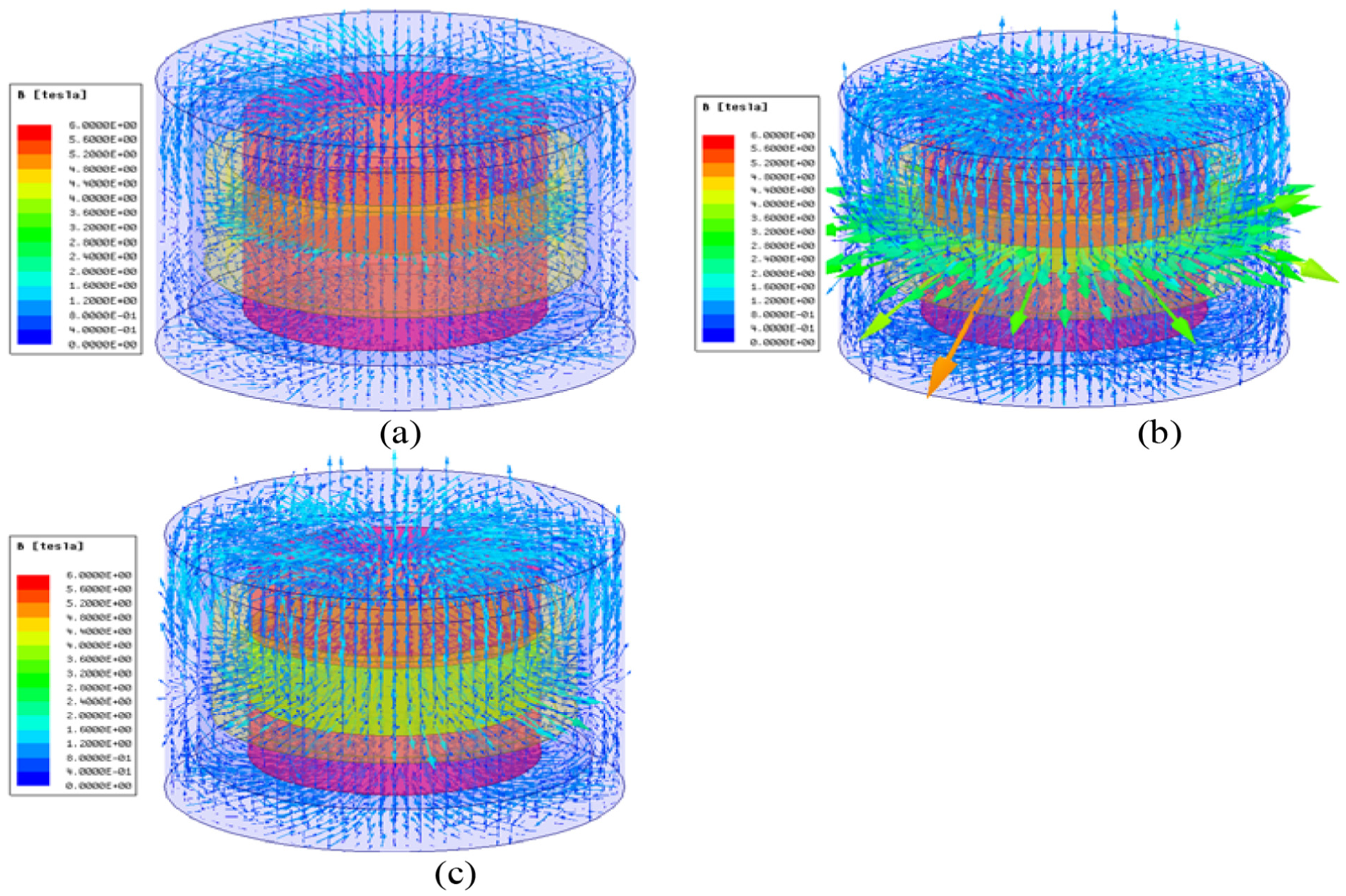
Influences of the magnetizer height MT on the distribution of magnetic flux density inside the entire VCM: (a) MT = 0; (b) MT = 3 mm; (c) MT = 8 mm.
The ohmic loss of the coil is also an important parameter needed to be considered. Although the resistivity of the coil is small, the eddy current, which will be converted to heat, is produced when the current is large, causing significant energy loss. The influence of the magnetizer height on the ohmic loss is shown in Figure 12. A maximum energy loss of 1.07e08 w/m3 is obtained with a magnetizer height of 3 mm, while a magnetizer height of 0 and 8 mm has an ohmic loss of 1.055e08 w/m3 and 1.04e08 w/m3, respectively. It seems that the variation of the magnetizer height has a very small influence on the ohmic loss of the coil. The difference among these three different values is less than 3%.

Influence of the magnetizer height MT on the ohmic loss of the coil: (a) MT = 0; (b) MT = 3 mm; (c) MT = 8 mm.
In this section, Figure 8 shows the results for the electromagnetic force under different magnetizer heights and yoke thicknesses when the driving current is fixed at 12 A. Based on these outcomes, the yoke thickness is set to 4 mm and the influences of the magnetizer height is analyzed. Figure 9 shows the results for the electromagnetic force under different driving currents. The influences of the magnetizer height on the magnetic induction intensity inside the air gap, the magnetic flux density inside the entire VCM, and the ohmic loss of the coil are shown in Figures 10–12. All the results indicate that the VCM performs best with a magnetizer height of 3 mm. The reason may be explained as follows. The electromagnetic force is generated by the function of the magnetic field on the electrified conductor. The role of the magnetizer is to guide and constrain the magnetic flux lines of the magnetic field. As the height of the magnetizer increases from 0 to 8 mm, the magnetic flux line is bounded well gradually. However, as the height of the magnetizer increases further, the height of the responsive permanent magnet decreases owing to a fixed total height, and the strength of the magnetic field decreases.
Yoke thickness
Finally, the influence of the yoke thickness is investigated. The electromagnetic force of the coil as a function of the yoke thickness is shown in Figure 13. The coil turns and the magnetizer height is set to 150 and 3 mm, respectively. When the yoke thickness increases from 1 to 3 mm, the electromagnetic force rises evidently. However, when the yoke thickness continues to rise, the electromagnetic force almost keeps at the same level.
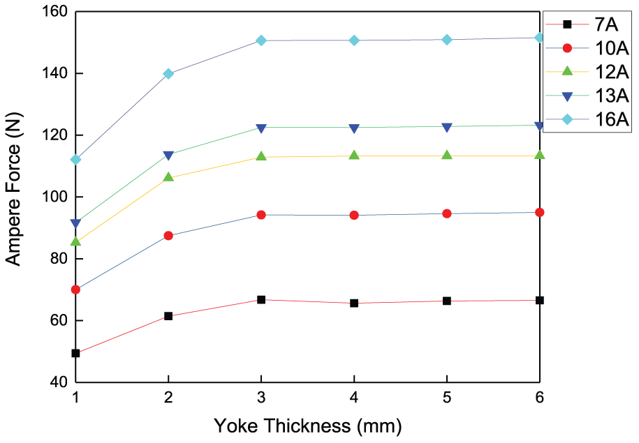
Results of the electromagnetic force versus the yoke thickness.
When the current is fixed at 12 A, the electromagnetic force with a yoke thickness of 2 mm is increased by 24.41% compared with that of 1 mm. The minimum of the force is 85.31 N with a yoke thickness of 1 mm while the maximum is 113.32 N with a yoke thickness of 6 mm. Because the magnetic saturation occurs when the yoke thickness is 1 mm and a slight magnetic saturation also occurs with a yoke thickness of 2 mm, the corresponding electromagnetic force shows a rapid decrease. Therefore, the yoke thickness must be chosen appropriately to avoid saturation. Otherwise, the performance of the VCM will be degraded. As the driving current increases from 7 to 16 A, the electromagnetic force basically increases proportionally.
Figure 14 shows the vector distribution of the magnetic flux density with different yoke thicknesses. It is evident that the magnetic flux density inside the VCM rises with the increase of the yoke thickness, which is denoted by the density of magnetic lines in Figure 14. The magnetic flux density reaches a maximum of 9.06 T with a yoke thickness of 6 mm. However, the growth rate of the magnetic flux density obviously declines if the yoke thickness exceeds 3 mm. Accordingly, the growth rate of the electromagnetic force also decreases.

Influences of the yoke thickness YT on the magnetic flux density inside the VCM: (a) YT = 1 mm; (b) YT = 4 mm; (c) YT = 6 mm.
Figure 15 shows the ohmic loss of the coil for different values of the yoke thickness when the driving current is 12 A. As the yoke thickness increases from 1 to 6 mm, the corresponding maximum ohmic loss only rises slightly from 1.10e07 to 1.15e07 W/m3. However, the electromagnetic force increases sharply from 85.31 to 113.25 N as the yoke thickness increases from 1 to 4 mm. If the ohmic loss is too large, a large amount of thermal energy dissipates, which will increase the power consumption and degrade the component life. When the yoke thickness is set to 4 mm, the performance of the VCM is close to the maximum and the extent of the ohmic loss is relatively small.
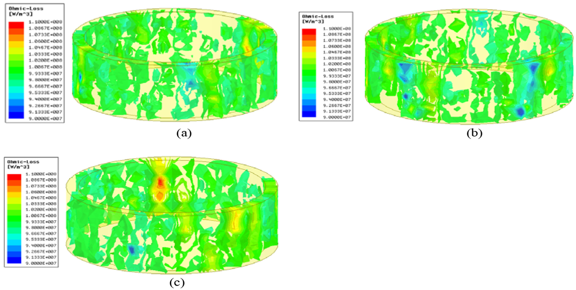
Influence of the yoke thickness YT on the ohmic loss of the coil: (a) YT = 1 mm; (b) YT = 4 mm; (c) YT = 6 mm.
According to the above analysis, the final parameters of the VCM are obtained and the results are shown in Table 4. The coil turns of the VCM is 150. The diameters of the magnets and the magnetizer are set to 28 mm. The heights of the magnets and the magnetizer are configured as 9.5 and 3 mm, respectively. The yoke thickness is 4 mm. The yoke and the magnets are made into cylindrical shapes, forming a sandwich structure. The coil is wrapped in a cylindrical wound. To balance the magnetic induction lines and constrain the displacement of the coil, the yoke is sealed by a cap and they are welded together after the coil, the magnets, and the magnetizer are installed.
Final parameters for the VCM.
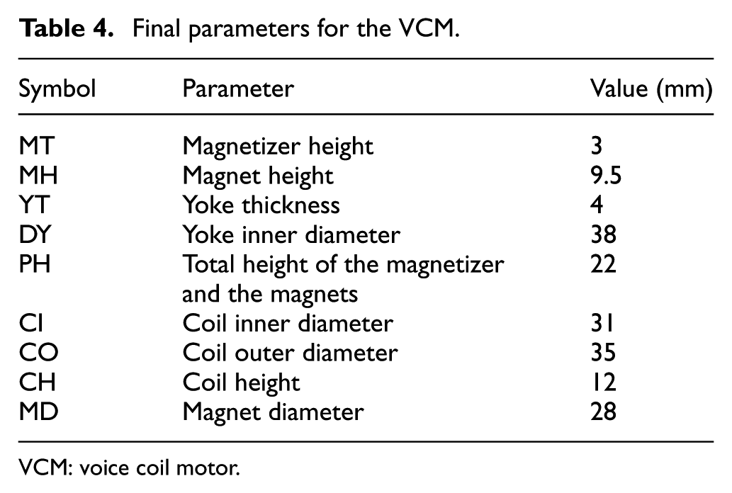
VCM: voice coil motor.
Dynamic response characteristics optimization
After the main dimensional parameters of the VCM are obtained, the dynamic response performance of the VCM is studied. The MEC method is used for the electromagnetic analysis. Disregarding the leakage reluctances of the air gap and the magnets, the electrical equivalent circuit of the VCM is shown in Figure 16.

Electrical equivalent circuit of VCM.
The kinetic model of the VCM can be denoted as


where F is the electromagnetic force and can be calculated by equation (7), Ff is the friction force, Fl is the spring force, Fd is the fuel damping force, Ff and Fd are small and neglected here, m is the gross mass of the coil, k is the spring coefficient, x is the displacement of the coil, a is the acceleration of the coil, and t is the time.
An electromagnetic force is imposed on the energized coil in a magnetic field, and its direction can be determined according to the left hand rule of the Ampere law. Therefore, the motion of the coil can be controlled by regulating the direction and magnitude of the excited current. The electromagnetic force is generally expressed by

where N is the number of turns of the coil, B is the magnetic flux density, i is the current, and L is the effective length of the coil, and ke is the coefficient of the electromagnetic force.
The energized coil moves in the magnetic field to produce a reverse electromotive force e. The voltage equation of the circuit based on Kirchhoff voltage law is described by


where R and L are the resistance and inductance of the coil, respectively, u is the applied voltage, i is the current in the circuit, e is the reverse electromotive force, and v is the velocity of the coil. The current of the coil i can be represented as a function of the electromagnetic force F according to equation (7) and then it is substituted into equation (8). According to equations (3)–(6), the electromagnetic force F can be expressed as a function of the displacement of the coil x. Hence, the relationship between the applied voltage and the displacement of the VCM coil can be derived as equation (10). In this equation, the friction term Ff and the damping term Fd are neglected.

Therefore, the transfer function G(s) can be obtained based on the Laplace transform

According to the above third-order transfer function, the equivalent block diagram of the closed-loop system is given in Figure 17. The inertial element 1/(Ls/R + 1) determines the response time of the system, and the gain factor k (equals to the spring coefficient) of the feedback loop determines the system stability.

Block diagram of the VCM.
The dynamic response characteristics of the VCM are important for the designed injector. 38 Therefore, it is necessary to investigate the relevant factors such as the mass m, the resistance of the coil R, and the coefficients of the spring force k and the reverse electromotive force ke. Based on the third-order system model of the VCM, the step responses are simulated when these parameters vary. The results are shown in Figure 18.
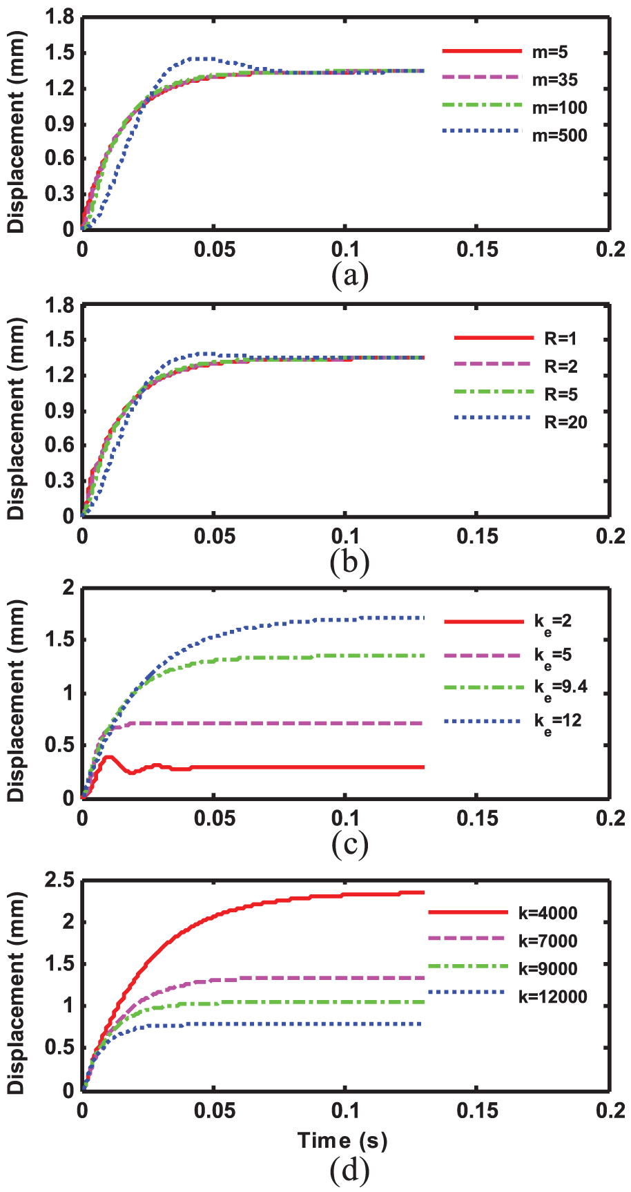
Influences of the design parameters on the dynamic response characteristics of the VCM: (a) the coil mass m; (b) the coil resistance R; (c) the coefficient of the magnetic force ke; (d) the coefficient of the spring force k.
Figure 18(a) shows the step response profiles with different values of m. Generally, the dynamic response time decreases as the total mass drops and the overshoot is also reduced. The third-order system will reduce to a first-order system if the total mass is too small. The influence for the value of R shows a similar trend in Figure 18(b). The dynamic response time is reduced if ke or k increases as shown in Figures 18(c) and (d). The static gain also increases when ke rises. As a contrast, the static gain descends evidently as k increases.
The influences of the parameters of m, R, ke and k on the dynamic response characteristics of the VCM are estimated and a satisfactory system response time is obtained by adjusting these parameters. The optimal results are listed in Table 5. Because these parameters affect and constraint each other, the dominate parameter should be given the highest priority. In addition, this MEC method should be considered together with the FEM method to ensure an appropriate steady and dynamic performance of the VCM.
Parameters of the VCM for the dynamic response performance analysis.

VCM: voice coil motor.
Experimental validation
The performance of the VCM is tested after the optimal parameters are determined. First, a test rig is setup to test the electromagnetic force generated by the VCM. The diagram of the test rig is shown in Figure 19, consisting of the test machine, the driving circuit, the data acquisition system, the ECU containing a microcontroller coded with the fuel injection software, and a computer used to communicate with the ECU. The supply voltage of the full-bridge driving circuit is 60 V. The control signals are determined based on the fuel injection maps.

Schematic of the test rig for the electromagnetic force measurement.
A photo of the test rig is shown in Figure 20. The Instron 5985 test machine with an accuracy of 0.01 N is used to measure the electromagnetic force generated by the coil of the VCM. When the coil is energized, an electromagnetic force is imposed on the coil due to the magnetic field generated by the permanent magnets. The test machine can measure the electromagnetic force, and a user interface is used to plot the measured data.

Photo of the test rig.
The measured results for two different working conditions are shown in Figure 21. The corresponding simulation results using the FEM method are also plotted. The first working condition is set to an engine speed of 3000 r/min and a throttle opening of 10%. The corresponding fuel injection pulse width is 1.25 ms and the results are given in Figure 21(a). First, a positive electromagnetic force is imposed to push the coil and the plunger to pressurize the fuel. At 1.25 ms, the driving current is set to 0 and the electromagnetic force falls to 0 accordingly. After a short delay, a negative force is generated to withdraw the coil. Finally, a smaller positive driving current is imposed on the coil again to prevent it from colliding with the bottom of the yoke.

Comparison of the electromagnetic force of the coil between the experimental data and the FEM results: (a) results under the working condition with an engine speed of 3000 r/min and a throttle opening of 10%; (b) results under the working condition with an engine speed of 6500 r/min and a throttle opening of 75%.
For the second test case, the engine speed is set to 6500 r/min and the throttle opening is 75%. The injection pulse width is 2.66 ms. The results are shown in Figure 21(b). It can be seen that the experimental data for the electromagnetic force are consistent with the simulated results basically. The errors are lower than 6%, which validates the former optimization results of the FEM method.
Fuel injection test
The GDI injector with a VCM is subsequently tested in a fuel injection test bench. The schematic of the test bench is shown in Figure 22. The test bench mainly consists of the ECU, the driving circuit, the injector, the low-pressure fuel supply system, the light source, the high-speed camera, and the installation bracket. The light source is a HYXYJ 1200 LED manufactured by HuaYuan Lighting Co., Ltd. The high-speed camera is a SA4 model provided by Photron Co., Ltd., which is used to capture the spray images with a speed of 10000 frame/s. The spray process of the injector can be obtained based on the macroscopic image technology.

Schematic of the spray test system for the GDI injector with a VCM.
The obtained spray images are displayed in Figure 23. The fuel injection duration is 1.5 ms and six representative images are displayed, which clearly manifest the developing process of the fuel spray. The fuel spray can be divided into two parts after 0.7 ms: the front gaseous regime and the rear liquid regime. At the beginning of the injection process, the fuel spray is liquid and then this front part is transformed into a gaseous state after a fine atomization and subsequent evaporation process.

Spray images of the GDI injector with a VCM.
At the start of the injection, the fuel in the liquid regime forms a spray cone angle of 22.2°. Then, the front of the fuel spray converted to a gas phase at 0.7 ms. With the development of the injection process, the spray droplets are broken and evaporated. The fuel atomization characteristic reaches the best situation at 1.5 ms. The GDI injector with a VCM can inject the spray plume directly into the cylinder with a high pressure, resulting in a good atomization and mixture formation process.
The designed VCM for the GDI injector can operate for more than 1000 hours during the engine testing. More engineering field tests are needed to give a comprehensive evaluation of the operation life. In this study, the prototype of the GDI injector with a VCM is approximately 100 dollars. The price will be lower for a massive production. Although the price of the injector with a VCM is higher than the traditional GDI injector, the cost of the entire fuel injection system will be less than that of a conventional one with a high-pressure fuel path.
Conclusions
In this study, a new type GDI injector with a VCM for the fuel injection system of a two-stroke aviation engine is presented. The working principle of the VCM is described. Then, an FEM of the VCM is setup and the influences of the design parameters are analyzed. The dynamic response characteristics of the VCM are also studied by an MEC method. Finally, the spray process is tested. The main conclusions are summarized as follows.
The VCM for the GDI injector operates as a linear actuator to pressurize the gasoline fuel. Compared with the conventional fuel injection system, the high-pressure pump and the common rail can be removed. The high-pressure fuel path can be shortened significantly. As a result, the fuel injection system can have a simple structure and a fast response.
The coil turns, the magnetizer height, and the yoke thickness of the VCM are three important dimensional parameters. The results show that the FEM method is an effective way to optimize these parameters. The coil turns determine the distributions of the magnetic field intensity and has a great influence on the electromagnetic energy conversion process. The magnetizer height and the yoke thickness must be adapted accordingly to achieve a compact structure with a minimum ohmic loss. The optimized results are validated by the measured electromagnetic force of the VCM on a test rig.
A MEC method is used to study the dynamic response characteristics of the VCM. The results show that the mass and resistance of the coil, the spring coefficient, and the coefficient of the electromagnetic force have a great impact on the dynamic response performance. Finally, the fuel spray process is measured using a high-speed camera. The spray can be atomized and evaporated smoothly and the feasibility of using VCM for the GDI injector of aviation engines is verified.
Footnotes
Acknowledgements
The authors thank for support from the National Natural Science Foundation of China (Grant No. 51876009) and the Science and Technology Innovation Foundation of Shenzhen (JCYJ20170817114345260).
Handling Editor: ZW Zhong
Declaration of conflicting interests
The author(s) declared no potential conflicts of interest with respect to the research, authorship, and/or publication of this article.
Funding
The author(s) received no financial support for the research, authorship, and/or publication of this article.