
Abstract
This article presents a structure-compacted single-gimbal control moment gyroscope, which is directly driven by an ultrasonic motor. The momentum wheel and the ultrasonic motor are designed and optimized based on software simulation. Considering the gyroscope’s dynamic disturbance and the nonlinearities of the ultrasonic motor, an expert control algorithm combining a two-degree-of-freedom pole placement controller with a pattern reasoning controller is designed for the gimbal servo system. The presented controller realizes a wide-range closed-loop speed control of the gimbal from 0.2 mrad/s to 1.6 rad/s, which is the base of the high stability and high precision of the control moment gyroscope. The presented control moment gyroscope and its controller board are manufactured and assembled for experiments. The experimental results show that the momentum wheel has almost no impact on the gimbal servo system at high speeds, but with the decrease in the gimbal speed the impact increases gradually.
Keywords
Introduction
A control moment gyroscope (CMG) has been used effectively in space systems, 1 , 2 single-wheel robotic systems, 3 and underwater robotic systems 4 for its torque characteristics. A single-gimbal control moment gyroscope (SGCMG) is a kind of CMG that is widely used as a key internal momentum exchange device for its feature of torque amplification. 5 , 6 Usually, four or five SGCMGs form an array to realize the attitude adjustment of a satellite. 7 , 8 A lightweight and integrated direct drive is the development trend of the agile small satellite.
An SGCMG mainly has a momentum wheel, a high-speed motor, a gimbal, a gimbal driving motor, and sensors. 9 The momentum wheel is driven by the high-speed motor, which will generate an angular momentum. The momentum wheel and the high-speed motor are fixed on the gimbal. When the gimbal is driven by the gimbal motor, the SGCMG will generate a torque since the angular momentum is changed. For a space satellite with SGCMG, it is expected to reduce the weight of the attitude adjustment unit, improve its load capacity, and simultaneously improve its maneuverability with high-speed stability. 10 , 11 The speed accuracy and stability of the gimbal frame are the key factors for the torque output accuracy and stability of an SGCMG. 12 The existing SGCMG gimbal servo system is mainly driven by an electromagnetic motor through a harmonic reducer. 13 , 14 The main limitations of this approach are a small power-to-weight ratio and a slow response, especially in the small agile satellite application. 15 It is meaningful to find a suitable actuator for the SGCMG.
The ultrasonic motor (USM) is a new type of motor that has the merits of a high-precision speed servo control, fast response, high angular resolution, self-locking, and no magnetic interference. The USM has great potential for space applications and has been successfully used in space robotics in the United States 16 and the Yutu lunar rover from China. 17 The USM possesses high friction when static and therefore can also function as mechanical brakes. 18 A space robotic arm driven by two USMs was described in Yoseph et al. 16 and greatly reduced the weight of the arm. Jang et al. 19 describe a control system used to operate a number of USMs that move the joints of a robotic arm. Multiple types of USMs are successfully used in lens driving of digital cameras. 20 In our project, a hollow USM will be applied as the driver of the gimbal frame of the SGCMG to improve the system performance and lower the weight of the gimbal servo system.
In an SGCMG driven by a USM, the high-frequency jitter resulting from the high-speed momentum wheel, the nonlinearities of the USM, and the frictional torque will have a great influence on the axis at low speeds. 21 , 22 Another problem with this application is the need for a wide speed range, especially in the ultra-low speed range, where the speed is less than 20 mrad/s. The classical proportional–integral–differential (PID) controller cannot address these problems satisfactorily. A variable structure system is a nonlinear controller that can cause chattering in the system, 23 which is not allowed in our system. A hybrid control strategy of a two-degree-of-freedom pole placement controller, called an RST controller, and a pattern reasoning (PR) controller will be introduced in this work. The RST controller is a two-degree-of-freedom digital controller and is based on the calculation of three polynomials (R, S, and T), which allow the pole placement of the closed loop and are widely used in computer control of industry.24–26 The PR controller is a type of expert control system that is based on the system response. 27 Both the RST controller and the PR controller are easy to realize in micro-control units.
In this article, first, the mechanical structure design and optimization of the SGCMG are presented based on the finite element modeling (FEM) software, and then the theoretical analysis is carried out. Second, the control system is addressed according to the control requirements. Finally, experiments are carried out to evaluate the mechanical system and the control strategies.
System structure and theoretical analysis
In the SGCMG, there are two kinds of mounting structures: frame and cantilever. In our project, the cantilever is selected for its simple structure and small size. The mechanical structure of an SGCMG driven by a hollow USM is shown in Figure 1. It mainly includes a high-speed rotor, a momentum wheel, a gimbal frame, a gimbal motor, and a gimbal sensor. The high-speed rotor driving the momentum wheel is working at a constant speed Ω, which will produce the constant angular momentum l. The high-speed rotor is mounted on the gimbal frame, which is driven by the USM. The axis of the gimbal is perpendicular to the rotary axis of the rotor. When the gimbal is rotating at speed

where J is the moment of inertia of the high-speed motor and the momentum wheel. From equation (1), τ is determined by

Structure and principle of the SGCMG.
Our goal is to control the gimbal speed
High-speed rotor and momentum
The high-speed rotor drives a momentum wheel working at a high speed value, which will bring an angular momentum. The angular momentum has a linear relationship with the inertia and the angular velocity of the momentum wheel of

Considering the needs of longer service life, less power consumption, faster speeds, and simpler maintenance, a brushless direct-current (BLDC) motor was selected as the driver; the structure of the BLDC is shown in Figure 2(a). To reduce the size, copper was selected as the material of the momentum wheel. Working at a high speed, the momentum wheel may excite a disturbance torque for machining error and material inhomogeneity. So the structure of the momentum wheel should be optimized. The optimized momentum wheel is shown in Figure 2(b).
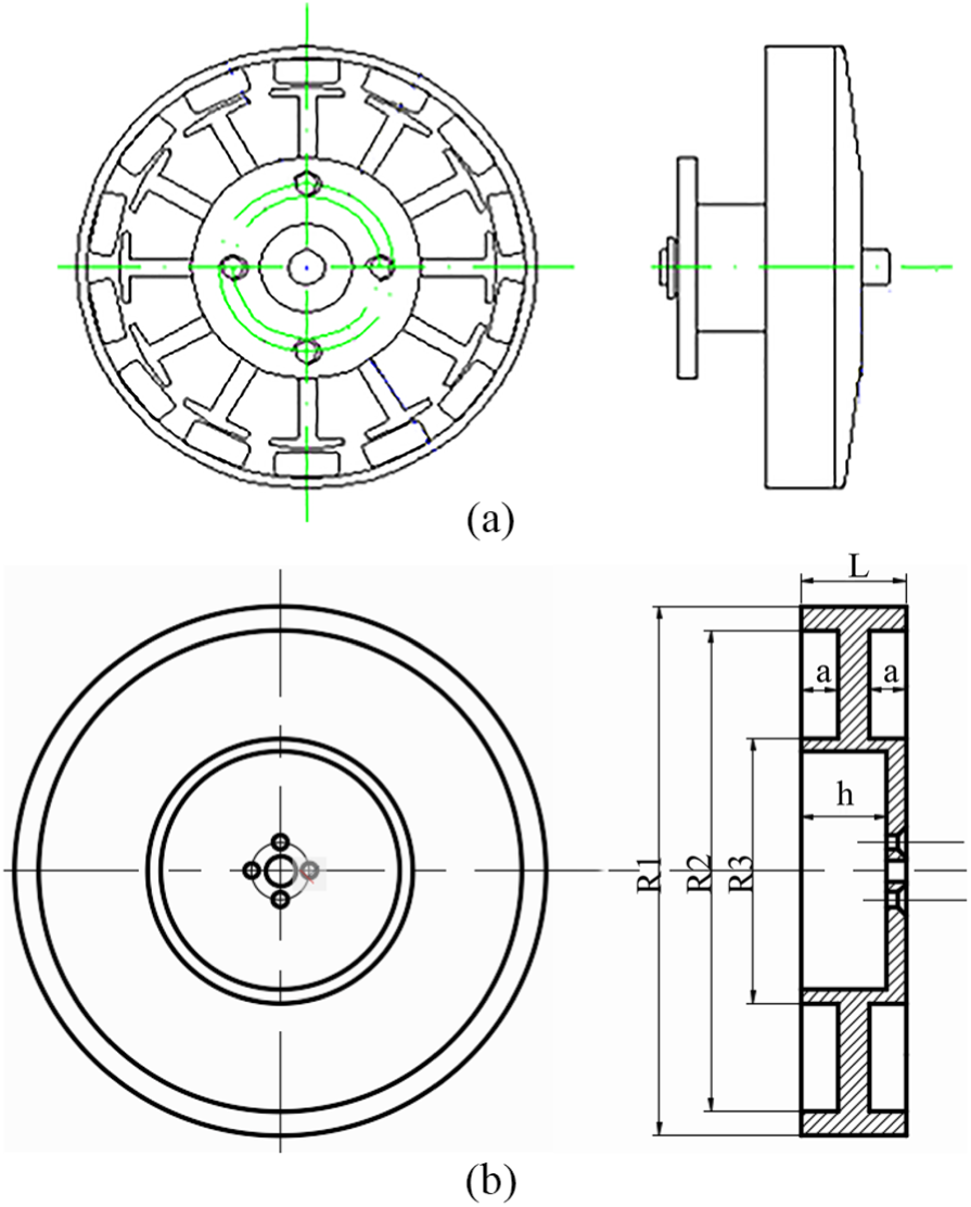
Structure of (a) the motor for the momentum wheel and (b) the momentum wheel.
The maximum working frequency of the momentum wheel is 200 Hz. The first-order natural frequencies of the optimized momentum wheel should be higher than this value. According to the structural size of the design, the first three order modes are calculated in the FEM (COMSOL Multiphysics; COMSOL Inc., Stockholm, Sweden). The results are shown in Figure 3(a)–(c), respectively. The first order mode is 3184 Hz, which is much higher than 200 Hz. The maximum stress inside the high-speed rotor is about 5.5 MPa, as shown in Figure 3(d). The optimized momentum wheel meets the requirements of structural strength and vibration.

The first three modes of the momentum wheel: (a) 3184 Hz, (b) 3825 Hz, and (c) 3830 Hz; (d) the stress distribution of the momentum wheel.
The gimbal and its driving rotor
The gimbal of the SGCMG is supported by a pedestal through two bearings, as shown in Figure 4(a). Underneath the pedestal are a high-precision angle sensor and the USM. The gimbal is connected with the USM through a key. In order to minimize the influence of the gyroscope torque on the USM, the bearing components are specially designed. The angle sensor is installed between the USM and the load-bearing component, which can monitor the position and speed of the axis in real time. More importantly, the sensor provides the feedback signal for the servo control system. At the same time, a conductive slip ring is also installed at the lower end of the USM. The USM is hollow type to let the wire of the conductive slip ring through; the structure of the USM is shown in Figure 4(b).

(a) The structure of the gimbal and (b) the USM for the SGCMG.
The original dimensions of the stator are determined according to Bolborici et al. 28 except the inner diameter of the support plat. To obtain a hollow enough hole in the stator, the diameter of the hollow hole was enlarged. But with the enlargement of the hole, a disturbance mode of B15 is introduced, which has a mode frequency of 39.152 kHz, as shown in Figure 5(a). This frequency is very close to the designed working frequency of 40.354 kHz, as shown in Figure 5(b). Through the FEM simulation and analysis, the thickness of the support plat has more impact on the B15 than on the B09, as shown in Figure 5(c). By adjusting the thickness of the support plat, the disturbance mode was separated far away from the working mode. A laser Doppler vibrometer (PSV-500F-B; Polytec Inc., Waldbronn, Germany) is employed to measure the frequency response of the stator, as shown in Figure 5(d). The experiments show that, around the working frequency, there are no disturbance modes.

Optimization of the USM: (a) the B15 mode; (b) the B09 mode; (c) the effect of the thickness of the support on the modes; (d) the laser vibration measurement of the optimized stator.
Theoretical analysis
According to the operating principle of the USM, its driven behavior usually has strong nonlinearities. 18 The two sinusoidal driven voltages shown in equation (3) create the two stationary flexural waves that are expressed in equation (4), which directly bend the stator. In the equation, W is the deformation amplitude of the stator, V and ω are the amplitude and frequency of the driven voltage, respectively, and ϕ is the phase difference between the two signals, which has its value usually set to ±π/2 in normal operations


With the help of the two same-amplitude standing waves, the stator will generate a traveling wave

where R(r) is the transverse displacement, ω = 2πf.
The traveling wave generates a tangential force to drive the rotor rotating under a suitable pressure. The tangential force that is transmitted to the rotor results in a driving torque τdr. An opposing torque τop is created when a load is added to the rotor. Garcia-Rochin 29 described the USM by

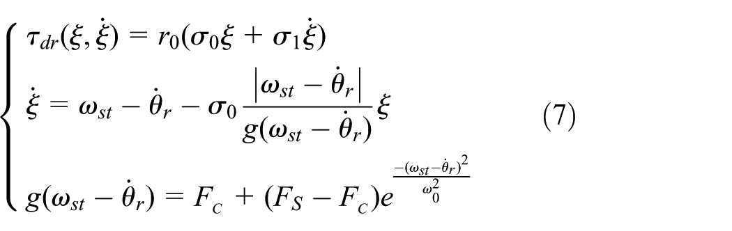

In this model, equation (6) describes the rotor dynamics, where Jr is the moment of inertia of the rotor, Cr is the friction coefficient, τdr is the driving torque that the stator transmits to the rotor, and τL is a load torque. Equation (7) describes the friction dynamics, where r0 is the mean radius of the inner and outer radii of the rotor, ξ describes the friction state, σ0 and σ1 are the spring-like micro-damping friction coefficients, ωst is the stator velocity, ω0 is the Stribeck velocity, FC is the Coulomb friction, and FS is the Stribeck friction. Equation (8) describes the stator velocity, where V0 and ω are the voltage and frequency applied to the piezoelectric material, respectively, ωn is the resonant frequency of the piezoelectric material, and c and χ are the coefficients depending on the electrical characteristics of the stator. This model allows for control of the motor using the frequency of the traveling wave, the voltage applied on the piezoelectric material, and the sign of the phase difference. In this article, the variable V0 is kept constant, α is
The momentum wheel running at a high speed will generate a dynamic disturbance torque on the gimbal for the dynamic imbalance. The disturbance torque leads to velocity fluctuation of the gimbal at the zero state. The measured disturbance from the gimbal axis is shown in Figure 6.

The dynamic interference of the momentum wheel.
From Figure 6, the dynamic disturbance torque of the rotor is a periodic signal. This disturbance torque is squarely proportional to the rotor speed and will bring a greater influence to the control accuracy. 21 The disturbance torque can be described as

where JwIx and JwIy are the inertia matrixes under the inertia rotor coordinate system and JwIx > JwIy; Ω is the rotor speed; and η and µ are the rotor imbalances.
Control system design
In the attitude adjustment mechanism of the spacecraft, the gimbal speed needs to vary from a low speed (0.2 mrad/s) to a high speed (1.5 rad/s). The robustness of the system should be considered when designing the controller at such a wide speed range. The RST controller is a robust and effective three-branch digital controller, which is widely used in industrial applications. A single control algorithm and strategy cannot meet the control target requirements. Especially in the ultra-low speed ranges, the single-frequency control mode fails to achieve satisfactory control results. Through open-loop experiments, the speed has better controllability by changing the pulse number of the drive signal periodically. The reasoning characteristic of the PR controller is suitable for this kind of control. For this reason, an expert control algorithm combining PR control with RST control is proposed in this article. The diagram of the combined controller is shown in Figure 7. The target area of speed control is divided into two sections to control. In the high target speed range of 0.01–1.6 rad/s, the speed regulation is realized by frequency modulation, and the conventional RST control algorithm is adopted. In the low target speed range of 0.2 mrad/s to 0.01 rad/s, the pulse number is the control variable and the PR controller is adopted.
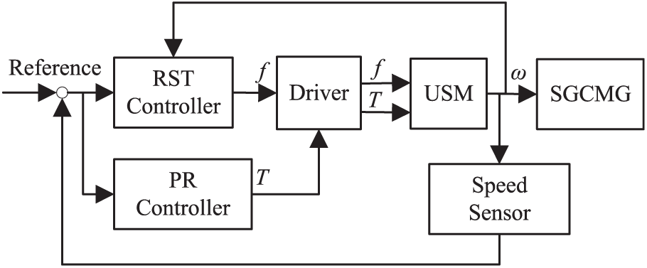
The diagram of the control system.
RST controller design
The RST controller consists of a discrete pole placement method based on the resolution of Diophantine equations. 24 , 30 As shown in Figure 8, this controller is composed of three discrete polynomials (R(z−1), S(z−1), and T(z−1)). The block B(z−1)/A(z−1) is the discrete-time open-loop transfer function of USR60. d represents the disturbance, u is the control signal, and r and y are the reference and measured positions, respectively


The diagram of the RST controller.
In Figure 8, B(z−1)/A(z−1) is the plant model. From section “Theoretical analysis,” the gimbal system is a second-order system, and the corresponding discrete system model can be described as

The closed-loop transfer function and the control signal are, respectively, given by
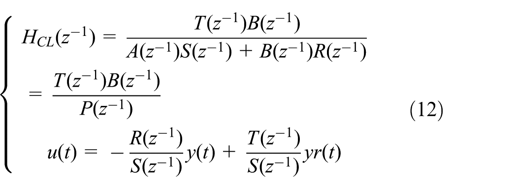
As shown in equation (12), T(z−1) appears only in the numerator, giving the supplementary degrees of freedom to this controller, and can be easily used to improve the tracking performance. The polynomials R(z−1) and S(z−1) are determined by the robust pole placement strategy and will be the solutions of the Diophantine equation 19

The transfer function between the disturbance p(t) and the output y(t) (output sensitivity function) is given by

This function allows the characterization of the system performance from the point of view of disturbance rejection. In addition, certain components of S(z−1) can be prespecified in order to obtain satisfactory disturbance rejection properties. The robustness of the discrete system needs to meet two indicators: (1) the modulus margin of the system is not less than −6 db, and (2) the delay margin of the system is not less than Ts. The index is transformed into a sensitivity function template

As a second-order system, the continuous-time transfer functions of the gimbal servo system can be expressed as

By choosing the appropriate damping and circular frequency values, the appropriate pole position can be obtained. The continuous system is discretized, and the value of P(z−1) in the RST control system is obtained. Here, ω0 = 1500 rad/s and ξ = 0.8, so

PR controller
The PR controller is analogous to an expert control system and has a structure as shown in Figure 9. It consists of four parts: the acquisition and processing of feature information, the set of feature patterns, the inference mechanism, and the set of control rules, where R is the referenced input and y is the output.

The controller of pattern inference.
The basic principle of the PR controller is to reflect the dynamic characteristics of the system to the output of the system deviating from the given error e and its first derivative

Four featured patterns.
In the phase plane shown in Figure 10,

where eB, e0, and ė0 are the normal numbers needed to control the decision.
According to the control requirements, the featured pattern classes can be scheduled for nine modes. They form a set of patterns

Among them, each of their predetermined patterns is divided into

In equation (19), e is the error, emax is the maximum allowable error, ė is the derivative value of error, ε is a small positive number, and c1 is a control parameter.
In the PR control system, based on e and ė, different control decisions will be adopted to control the system as soon as possible to eliminate the deviation and meet the specified control target requirements. For the gimbal system of the SGCMG driven by the USM, e is the difference signal between the target speed and the actual measurement speed and ė is the trend of change of e. According to the mode reasoning control principle, the control algorithm set is

The specific expressions of U are

where uPID is the traditional PID controller.
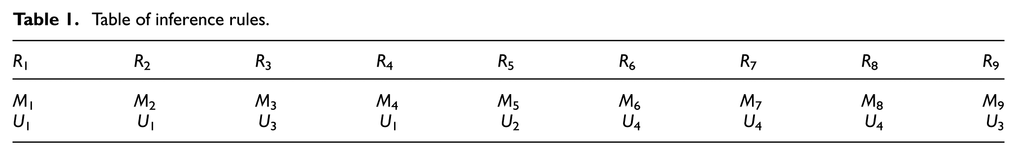
The set of reasoning rules is shown in Table 1. The form of reasoning is based on the feature pattern set M and the control algorithm set U as a conclusion. For example, the first rule of reasoning is expressed as R1: if M1, then U1.
Table of inference rules.
Experiments
An embedded microcontroller TMS320F28335 (Texas Instruments, Dallas, TX, USA) was adopted to implement the designed control system. It has a pulse width modulation resolution of 6.67 ns, which can realize the high-precision frequency control of the USM. The control algorithm is realized by the C programming language. The diagram of hardware implementation of the control system is shown in Figure 11. During the experiments, the high-speed rotor was accelerated to 6000 r/min and kept constant with the help of another speed controller. The machined USM and the momentum wheel are shown in Figure 12(a) and (b), respectively. The photograph of the assembled SGCMG and the control board is shown in Figure 12(c).

Block diagram of controller realization.
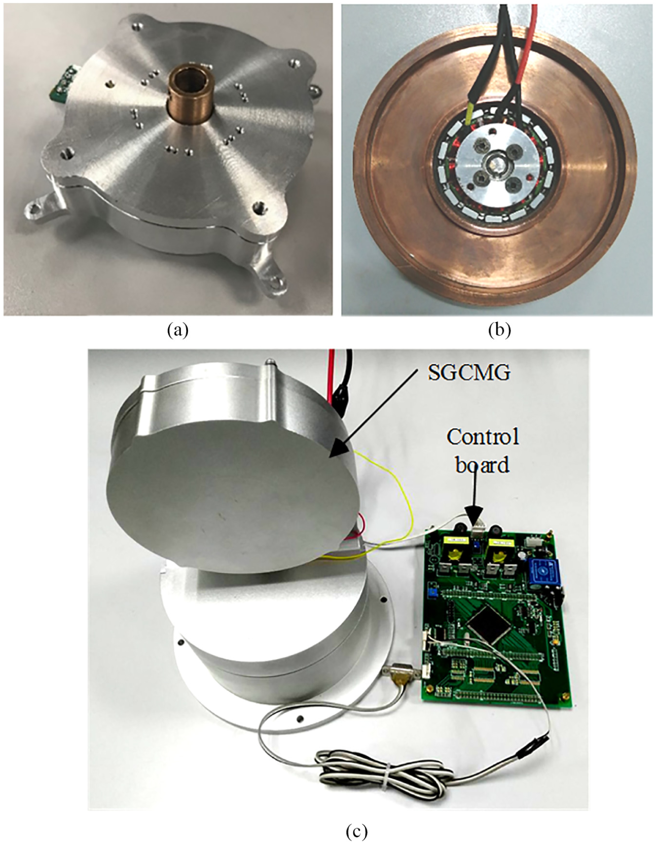
Photographs of (a) the USM, (b) the momentum wheel, and (c) the assembled SGCMG and the control board.
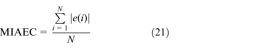
To evaluate the control results, we introduce the mean integral absolute error criterion (MIAEC); the definition of the MIAEC is
Within the ultra-low speed range, the closed-loop control results at three typical speed values of 0.2, 1.0, and 2.0 mrad/s are shown in Figure 13(a)–(c), respectively. At each speed value, the control results are compared when the momentum wheel is working on or off. From Figure 13(a), at a low speed of 0.2 mrad/s, the momentum wheel disturbances have great influences on the system and at some positions may excite unexpected oscillation. As the referenced speed increases, the disturbances decrease gradually, as shown in Figure 13(b) and (c). It can be seen from Figure 13(d) that the difference of the MIAEC value at the same referenced speed point decreases with the increase in the expected speed.

Low-speed closed-loop control: (a) at the speed of 0.2 mrad/s, (b) at the speed of 1 mrad/s, and (c) at the speed of 2.0 mrad/s; (d) the MIAECs.
As described in section “Control system design,” there is a critical speed from the PR controller to the RST controller, according to the referenced speed. From the experiments shown in Figure 14(a), the closed-loop speed stabilities are close at the turning speed of 10 mrad/s. The influences of the momentum wheel on the two controllers are shown in Figure 14(b) and (c), respectively. As shown in Table 2, the MIAEC value has shown that the momentum wheel has the same degree of influence on both the PR controller and the RST controller, and the influences can be ignored at this speed point and at higher speeds.

Comparison of the PR controller and the RST controller at the critical speed: (a) PR controller versus RST controller, (b) PR controller, and (c) RST controller.
MIAEC values with different controllers.

MIAEC: mean integral absolute error criterion; PR: pattern reasoning.
Within the higher speed range, the closed-loop control results at three typical speed values of 20 mrad/s, 0.1 rad/s, and 1.0 rad/s are shown in Figure 15(a)–(c), respectively. We compared the presented RST control results (the red line) with the PID control results (the black line), and the parameters of the PID are determined by the Ziegler–Nichols settling method. At the referenced speed of 20 mrad/s, the maximum speed error and the MIAEC of the PID controller are 5.4% and 0.013, respectively. The maximum speed error and MIAEC of the presented RST controller are 3.6% and 0.009, respectively. When the referenced speed increased, the control performances of the two controllers improved and the RST controller still shows the excellent ability of anti-interference.
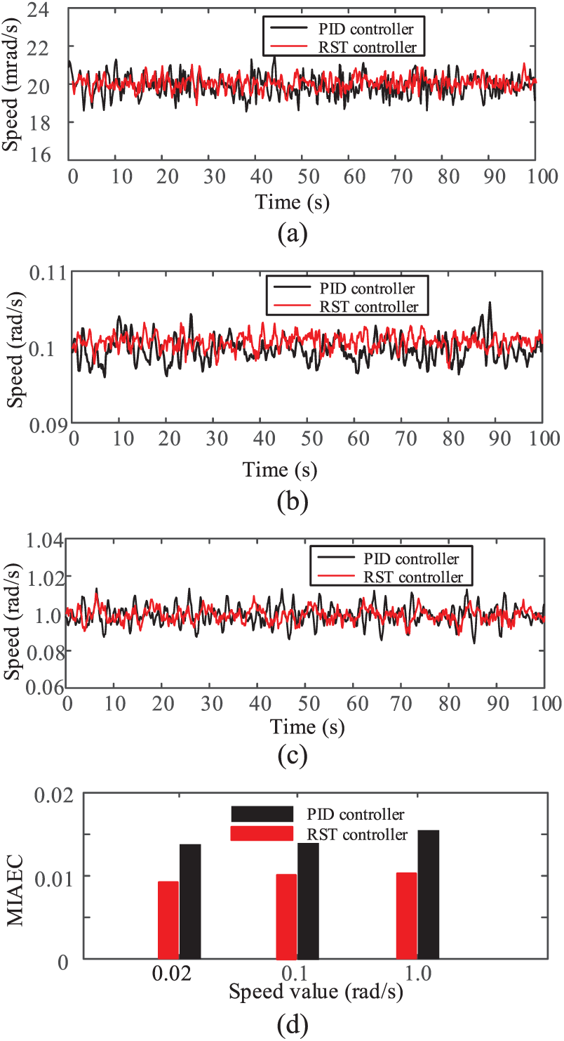
High-speed closed-loop control: (a) at the speed of 20 mrad/s, (b) at the speed of 0.1 rad/s, and (c) at the speed of 1.0 rad/s; (d) the MIAECs.
From the experiments, the SGCMG directly driven by the hollow USM could realize wide-range speed tracking control with the presented RST controller and PR controller. This means that the presented SGCMG could attain high-precision maneuverability of the satellite. One question that needs to be noted, however, is the dynamic disturbance from the high-speed momentum wheel at ultra-low gimbal speeds. According to the experiments, the imbalance of the momentum wheel and the friction of the gimbal are the main sources of the disturbance presently. So, in the future study, we will have more investment in manufacturing the momentum wheel and the gimbal. From the view of control system optimization, a higher performance control strategy could lower the disturbances.
Conclusion
In this study, an SGCMG driven by a hollow USM was presented. The structure and the working principle of the SGCMG were introduced in detail. One important problem is the disturbance on the gimbal axis resulting from the high-speed momentum wheel. To reduce the disturbance, the structure of the momentum wheel was optimized with the help of the FEM software. As the key actuator, the USM for the SGCMG was designed and optimized carefully to avoid the disturbance mode. The control system plays an important role in this study, considering the wide speed range the expert control algorithm was presented with. The presented controller was realized on an embedded control system, and the experimental studies were carried out. In the presented control system, the PR controller and the RST controller are fused, and the gimbal speed closed-loop control is realized from 0.2 mrad/s to 1.6 rad/s. What should be noted is that the disturbance from the high-speed vibration of the momentum wheel exceeds our expectation in a low speed range. In the future study, we will conduct some theoretical research and structure optimization on the vibration coupling between the gimbal and the momentum wheel. At the same time, the control system will be further improved based on theory and practice.
Footnotes
Handling Editor: Sunan Huang
Declaration of conflicting interests
The author(s) declared no potential conflicts of interest with respect to the research, authorship, and/or publication of this article.
Funding
The author(s) disclosed receipt of the following financial support for the research, authorship, and/or publication of this article: This work has been supported by the National Natural Science Foundation of China (No. 51575260) and the Long-Life Technology of Precision Rotation and Driving Mechanisms of Beijing Key Laboratory Open Fund (No. BZ0388201804).