
Abstract
Power skiving is a modern and productive method in the manufacturing of cylindrical internal gears and external gears. However, pose errors of workpiece and cutter are caused by clamping, cutting force, and deformation of heat, which make the tooth deviation present a feature of complexity and diversity in the process of gear skiving. First, a mathematical model with workpiece and cutter pose errors is proposed to investigate the influence of sensitive error on tooth deviation by an example of internal gear skiving. Second, the correlation of tooth deviation with respect to eccentric error of workpiece, eccentric error of cutter, tilt error of cutter, and the multiple errors is studied. The sensitive errors are derived from the tooth deviation by using an orthogonal analysis with workpiece and cutter pose errors. Last, the experimental results show the validity of the numerical analysis results, and the influence of sensitive pose errors on tooth deviation can be used to identify the possible error in power skiving, as well as in gear generating method.
Introduction
Power skiving is a novel and efficient method for the manufacturing of high accuracy cylindrical gears, especially for the internal gears. Not only is the efficiency and accuracy better than hobbing and shaping of the small module gears, but the spiral planetary gears without relief groove can be machined as well. Many scholars1–3 in different countries have made lots of preliminary exploration on gear skiving since 1960s, such as Germany, the United States, and Japan. Nevertheless, the lag of advanced numerical control technology, precision of machine tools, and adequate tool life hindered an effective industrial application. In recent years, with the improvements in stiff electric spindle, independent electronic gearbox, and advanced manufacture technology of cutter, varieties of machine tools4–6 using power skiving method demonstrate that gear skiving is capable of being a high-productive and flexible alternative to the manufacture of small gears in market. In terms of the current literature,7–11 lots of research work have been investigated thoroughly about the modeling methods of cutter design, cutting mechanism, and tool life.
However, in the process of gear skiving, the pose errors of workpiece and cutter are coupled with each other due to the clamping, cutting force, and cutting heat, which have a significant influence on the machining accuracy of tooth surface, making it difficult for skiving machine tool to achieve the expected precision. Thus, it is important to investigate the influence of sensitive pose errors on cylindrical gear tooth deviation in skiving. At present, with regard to error modeling and error analysis of gear machine tools, the literature mainly focus on geometric error modeling and thermal error modeling of gear hobbing and gear grinding.12–14 Only Guo et al. 15 studied the influences of tool setting errors on gear skiving accuracy by discussing the micro-morphology of the generated tooth surface. In fact, power skiving is different from the traditional gear generating method as a new gear cutting method. On one hand, power skiving is used for machining small gears, usually the module is less than 5 mm, due to the limitation of crossed angle and cutting speed. The smaller the gear modulus, the little the tooth deviation is required; hence, tiny pose error of workpiece and cutter will result in a high tooth deviation. On the other hand, dry cutting in the process of gear skiving results in a higher cutting force, as well as an increasing cutting heat, which make the tooth deviation present a feature of complexity and diversity.
Mathematical model of gear skiving
Principle of gear skiving
The machine setup of power skiving for an internal cylindrical gear is shown in Figure 1. Consider that the Cartesian coordinate systems

Machine setup of power skiving for an internal cylindrical gear.
In case of working a helical internal gear, the working motion is oriented in z1-axis direction, but an incremental angular velocity Δω1, which depends on the axial feed velocity v0, has to be added to ω1. The incremental angular velocity of workpiece, Δω1, is determined by the following equation

where
Therefore, the relationship between the angular velocity of workpiece and cutter and axial feed satisfies the following relation

where zt is the tooth number of skiving cutter.
On the contrary, if the skiving cutter provides the incremental movement, the relation can be represented as

where β2 is the helix angle of cutter.
According to the gear principle,
16
using a work gear as a virtual tool by generate method, the derivation of enveloped space is spiral tooth surface. Assuming that the surface of workpiece and cutter is represented in parametric form


where (u, θ) are the surface parameters of workpiece and cutter, and φ1 and φ2 are the rotation angles of workpiece and cutter, respectively.
The transformation matrices

where
Coordinates transformation in homogeneous matrix representation
Referring to the multi-body system theory, the pose of representative elementary volume Bj can be determined by coordinate transformation from its lower numbered body array B0. Considering that Cartesian coordinates
As shown in Figure 2, in the influence of workpiece pose errors, gear has the angular errors {Δαm, Δβm, Δγm} and the translational errors {Δam, Δbm, Δcm} of three directions along the coordinate axes, and also determines whether the coordinate system


Coordinate systems of gear skiving.
As {Δα, Δβ, Δγ} is the micro-small amount in gear setting errors, thus, Δk(k = α, β, γ) → 0, and cosΔk ≈ 1 and sinΔk ≈ Δk. Ignoring the higher order infinitesimal, the homogeneous transformation matrix is represented by

In the same way, the Cartesian coordinates

Therefore,

Considering Δc and Δγ as the initial cutting flank of z-axis and c-axis, which is irrelevant to the accuracy of tooth flank, assume that Δcm = 0, Δγm = 0, Δcn = 0, and Δγn = 0. Since Δα and Δβ belong to the tilt error of plane O – xy, the Δβ can be represented as one tilt error, that is, Δαm = 0 and Δαn = 0. For a workpiece, the tilt error is determined by Δβm = atan(ε/rc), where δ is the ending runout and rc is the measure radius. While δ < 0.01 mm, as a result, Δβm ≈ 0. For a cutter, the tilt error Δβn may be varying in a range of ±0.2° in actual machining process. Furthermore, Δam and Δbm can be expressed as

where (e1, e2), (ψ1, ψ2), and Δβn are eccentric error, phase angle of eccentric error, and tilt error of cutter, respectively.
Then, substituting equation (11) into equation (6) yields the tooth surface equation with setting errors

Consequently, tooth surface deviations, including profile form deviation, ffα, profile slope deviation, fhα, helix form deviation, ffβ, helix slope deviation, fhβ, single flank deviation, ±fpt, and cumulative pitch deviation, Fp, can be derived by

According to Fang et al., 12 the tooth surface deviations δ (fhα, ffα, fhβ, ffβ, Fp, ±fpt) are calculated in transverse section; as shown in Figure 3, tooth deviation of any point P(xp, yp) is determined by the normal distance PB between actual tooth surface and theoretical tooth surface. Here, the formula for the point P with respect to theoretical tooth surface at B is given by

where
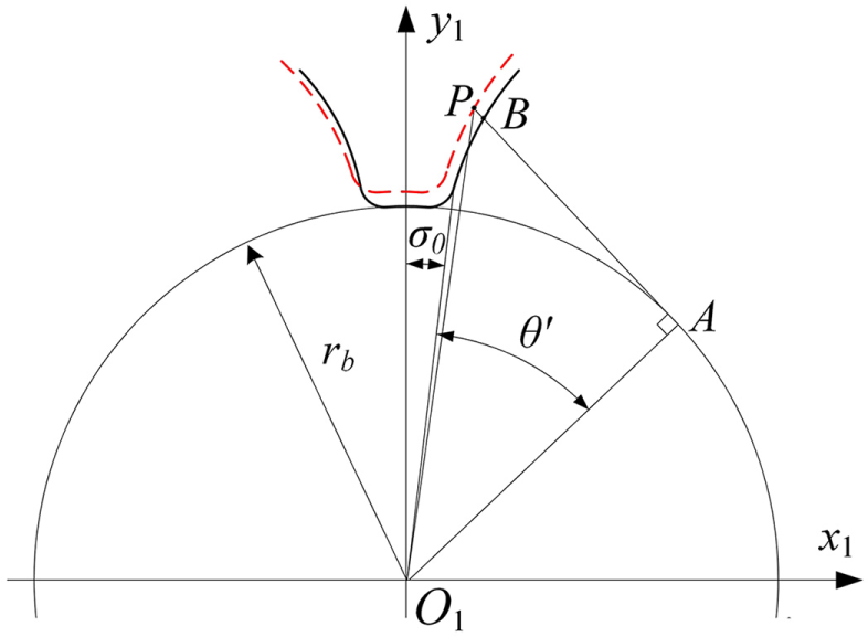
Calculation of tooth deviation.
Influence of sensitive errors on tooth deviation in power skiving
Recalling from the transformation matrix, the main pose errors, workpiece eccentric error e1, cutter eccentric error e2, and cutter tilt error Δβn should be taken into account in analyzing the sensitivity of errors toward tooth deviation. So the results of individual error are discussed by designing an orthogonal experiment of numerical simulation. The key parameters of helical internal gear are number of teeth zg = 98, module mn = 2 mm, pressure angle αn = 20°, helix angle β1 = 15°, and gear width Bw = 20 mm, while the key parameters of skiving cutter are number of teeth zt = 50, module mn = 2 mm, helix angle β1 = 5°, and cutter tilt angle Σ = 20°. In order to explain the influence of sensitive errors on tooth deviation, the small setting errors in the simulated analysis of power skiving are in accordance with manufacturing practice. Because of the symmetry of workpiece eccentric error and cutter tilt error, the workpiece eccentric error e1 = 0.02 mm and cutter tilt error Δβn = 0.2°. Considering the phase difference of setting errors, the cutter eccentric error e2 = ±0.02 mm.
Analysis of individual error
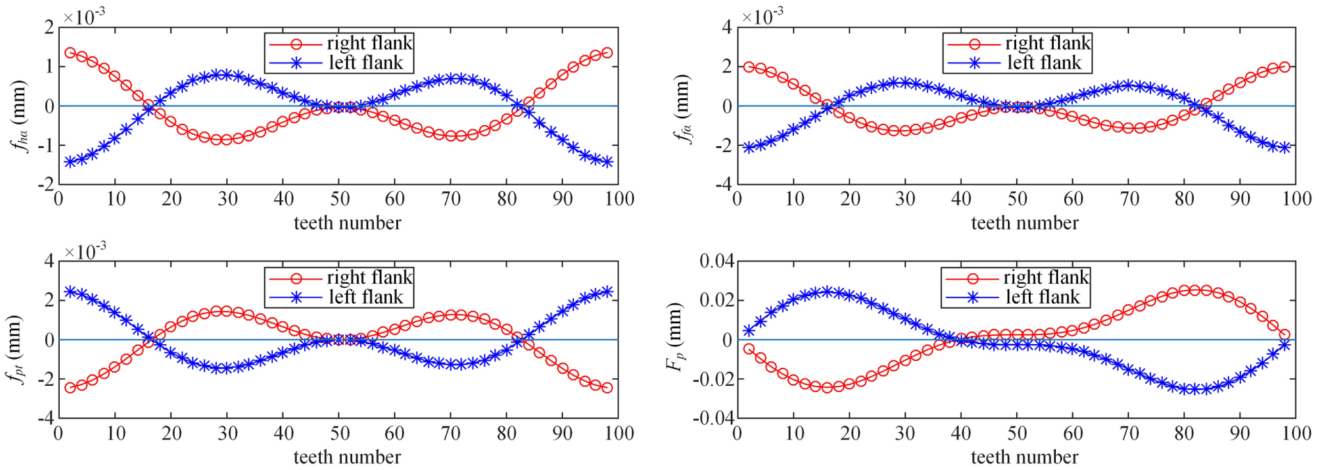
Figure 4 shows the influence of gear eccentric error (e1 = 0.02 mm) on tooth deviation. The maximum error on the right flank and left flank is selected as the evaluation value of tooth deviation; if the maximum error on tooth flanks is less than 0.003 mm, it is considered as insensitive error with respect to pose error. Conversely, if the maximum error on tooth flanks is more than 0.005 mm, it is considered as sensitive error with respect to pose error. As shown in Figure 4, deviations derived from the maximum error of each tooth flank present a cosine curve or a sine curve in the influence of workpiece eccentricity. The profile slope deviation, fhα (<0.001 mm), and profile form deviation, ffα (<0.001 mm), are insensitive to workpiece eccentric error. The helix slope deviation, fhβ (≤0.001 mm), and helix form deviation, ffβ (≤0.001 mm), are insensitive to workpiece eccentric error as well. However, the cumulative pitch deviation, Fp (≤±0.02 mm), is sensitive to workpiece eccentric error, the maximum pitch deviation is twice as much as the eccentric error, while the single flank deviation, ±fpt (≤±0.002 mm), is insensitive to workpiece eccentric error. In fact, the influence of gear eccentric error on tooth deviation is the same as used in other gear cutting method, such as gear grinding method in Fang et al., 12 because the rotary center of gear is off machine center.

Influence of workpiece eccentric error (e1 = 0.02 mm) on tooth deviation.
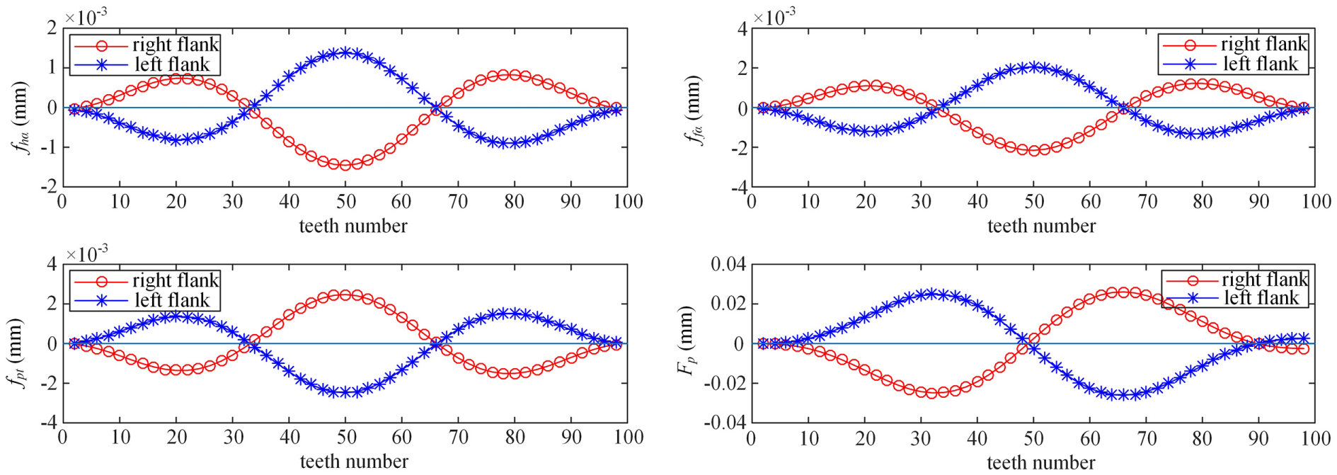
Figure 5 shows the influence of cutter eccentric error (e2 = 0.02 mm) on tooth deviation. Deviations on each tooth flank are different from the gear eccentric error (e1 = 0.02 mm); they show a multi-cosine curve or a multi-sine curve in the influence of cutter eccentricity, that is, the rotational speed of gear and cutter is determined by the ratio of tooth number, zg/zt. As shown in Figure 5, the profile slope deviation, fhα (<0.001 mm), and profile form deviation, ffα (<0.001 mm), are insensitive to cutter eccentric error. The helix slope deviation, fhβ (≤0.001 mm), and helix form deviation, ffβ (≤0.001 mm), are insensitive to cutter eccentric error. However, the cumulative pitch deviation, Fp (≤±0.01 mm), is sensitive to cutter eccentric error, the maximum pitch deviation is equal to the eccentric error, while the single flank deviation, ±fpt (≤±0.002 mm), is insensitive to cutter eccentric error.

Influence of cutter eccentric error (e2 = 0.02 mm) on tooth deviation.
Figure 6 shows the influence of cutter tilt error (Δβn = 0.2°) on tooth deviation. Deviations on each tooth flank show a linear correlation in the influence of cutter tilt error. The results show that deviations on each tooth are the same because the inclined cutter keeps a fixed position to cut every tooth flank of gear. As shown in Figures 6 and 7, the profile slope deviation, fhα (=0.008 mm), is sensitive to cutter tilt error, while the profile form deviation, ffα (<0.002 mm), is insensitive to cutter tilt error. Besides, the cutter tilt error has no effect on helix slope deviation, fhβ (<10−6 mm), and helix form deviation, ffβ (<10−6 mm). The cumulative pitch deviation, Fp (≤0.001 mm), and single flank deviation, ±fpt (<10−5 mm), are insensitive to cutter tilt error.

Influence of cutter tilt error (Δβn = 0.2°) on tooth deviation.
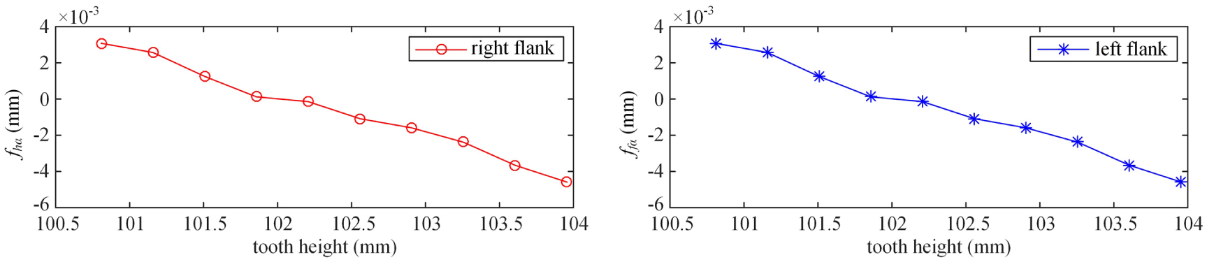
Influence of cutter tilt error (Δβn = 0.2°) on profile slope deviation.
Since the helix deviation, including profile slope deviation and profile form deviation, is insensitive to the eccentricity and tilt error, the influence of multiple errors on helix deviation will not be shown in the following discussion.
Analysis of multiple errors
Compared with the individual error, the multiple errors, such as the workpiece eccentric error and cutter eccentric error, workpiece eccentric error and cutter tilt error, and cutter eccentric error and cutter tilt error, which can be considered as more than one individual error, influence the tooth deviation. Figures 8 and 9 show the influence of workpiece and cutter eccentric error (e1 = 0.02 mm, e2 = ±0.02 mm) on tooth deviation. As the index of tooth number increases, both workpiece and cutter eccentric error contribute to the maximum tooth deviation. Particularly, for the cumulative pitch deviation, it comes to the maximum (Fp = 0.06 mm) on the left flank when the tooth number of workpiece zg = 16 and zg = 32, respectively, in Figures 8 and 9, assumes that the total deviation satisfies the principle of linear superposition with respect to individual tooth deviation of different error . However, the maximum tooth deviation is, on the contrary, on the right flank. Thus, it can be seen that the diversity of tooth deviations on both flanks is determined by the phase angle of eccentric errors, as well as the ratio of tooth number, zg/zt. Such a case can be used to judge whether the workpiece or the cutter has eccentricity and whether the errors have the same phase angle of eccentricity.
Influence of workpiece and cutter eccentric error (e1 = 0.02 mm, e2 = +0.02 mm) on tooth deviation.
Influence of workpiece and cutter eccentric error (e1 = 0.02 mm, e2 = –0.02 mm) on tooth deviation.
Figures 10 and 11 show the influence of eccentric error and tilt error (e1,2 = 0.02 mm, Δβn = 0.2°) on tooth deviation. As the index of tooth number increases, both workpiece eccentric error and cutter tilt error contribute to the maximum tooth deviation. Particularly, for the profile slope deviation, fhα, the average maximum on both flanks is 0.008 mm, and for the cumulative pitch deviation, the maximum deviation is 0.04 mm, if e1 = 0.02 mm, and the maximum deviation is 0.02 mm, if e2 = 0.02 mm. Such a case can be used to identify whether the workpiece or the cutter has eccentricity and whether the cutter tilt error exists.

Influence of workpiece eccentric error and cutter tilt error (e1 = 0.02 mm, Δβn = 0.2°) on tooth deviation.

Influence of cutter eccentric error and tilt error (e2 = 0.02 mm, Δβn = 0.2°) on tooth deviation.
Figure 12 shows the influence of eccentric error and tilt error (e1 = 0.02 mm, e2 = 0.02 mm, Δβn = 0.2°) on tooth deviation. Both eccentric error and tilt error contribute to the maximum tooth deviation, for example, the average profile slope deviation fhα is 0.008 mm, and the cumulative pitch deviation Fp is 0.06 mm, so the maximum tooth deviation on both flanks exerts linear superposition of individual error.

Influence of eccentric error and tilt error (e1 = 0.02 mm, e2 = 0.02 mm, Δβn = 0.2°) on tooth deviation.
In the numerical example, the tooth deviations are obtained using an orthogonal analysis method, and the results in Tables 1 and 2 are concluded as follows:
The cumulative pitch deviation is sensitive to eccentric error of workpiece, while the profile deviation and helix deviation are insensitive to eccentric error of workpiece. The maximum cumulative pitch deviation is twice the eccentric error of workpiece. Deviations on each tooth flank show a cosine curve or a sine curve in the influence of workpiece eccentricity.
The cumulative pitch deviation is sensitive to eccentric error of cutter, while the profile deviation and helix deviation are insensitive to eccentric error of cutter. The maximum cumulative pitch deviation is equal to the eccentric error of cutter. Deviations on each tooth flank show a multi-cosine curve or a multi-sine curve determined by the phase angle of eccentric errors, as well as the ratio of tooth number, zg/zt.
The profile slope deviation is sensitive to tilt error of cutter, while the helix deviation and pitch deviation are insensitive to tilt error of cutter.
The tooth deviations are linear correlation to the individual tooth deviation of different pose errors, such as workpiece eccentric error, cutter eccentric error, and cutter tilt error.
The phase angle of workpiece and cutter eccentricity causes the diversity of tooth deviation; the total tooth deviation can be considered as the superposition of individual tooth deviation derived from eccentric error or tilt error.
Orthogonal analysis with workpiece and cutter error (mm).

Sensitive errors of workpiece and cutter (mm).

Experiment and discussion
To verify the validity of the proposed numerical analysis method, as shown in Figure 13, an experiment is conducted on a power skiving machine tool. The basic parameters of power skiving in the experiment are shown in Table 3. After finishing the machining gear, the teeth of workpiece are numbered in sequence; three numbered teeth, 1, 34, and 67, are selected to measure the profile deviation.

Experiment of gear skiving with pose error: (a) skiving cutter and (b) workpiece by skiving.
Basic parameters of power skiving in the experiment.

The above analysis shows that the pitch deviation and profile deviation are sensitive to the setting error, and because the pose errors have nearly no influence on the helix deviation, we just discuss pitch deviation and profile deviation in the experimental results. In order to reduce the work of experiment, only three typical machining pose errors are selected to verify the numerical analysis in the experiment. As shown in Table 4, the experimental results and expected numerical results are compared. (1) In eccentric error of workpiece, the maximum profile slope deviation is 3.2 µm and the maximum cumulative pitch deviation is 45 µm, which is higher than the numerical value 40 µm by 12.5%. (2) In eccentric error of workpiece and cutter, the maximum profile slope deviation is 3.5 µm and the maximum cumulative pitch deviation is 57 µm, which is lower than the numerical value 60 µm by 5%. (3) In eccentric error and tilt error, the maximum profile slope deviation is 10.6 µm and the maximum cumulative pitch deviation is 68 µm, which is higher than the numerical value 60 µm by 13.3%. Regarding the uncertain factors in the process of power skiving, the experimental results agree well with the numerical analysis. The results demonstrate the cumulative pitch deviation is sensitive to eccentric error, while the profile deviation is insensitive to eccentric error. The profile slope deviation is sensitive to tilt error of cutter, while the helix deviation and pitch deviation are insensitive to tilt error of cutter. Besides, multiple errors result in the diversity of tooth deviation; the sensitive tooth deviation can be considered as the superposition of multiple errors.
Comparison of numerical results and experimental results (mm).

Conclusion
By using a numerical and experimental example for analyzing the sensitive error in power skiving, different variants of pose error on tooth deviation can be simulated, including the eccentric error of workpiece, eccentric error of cutter, tilt error of cutter, and the multiple errors. It can be concluded as follows:
While the profile slope deviation is sensitive to cutter tilt error, the cumulative pitch deviation is sensitive to eccentric error. In case of the workpiece eccentric error only, the maximum cumulative pitch deviation is twice the eccentric error by a single cosine or sine curve, if the cutter with an eccentric error only, the maximum cumulative pitch deviation is equal to the eccentric error by a multi-cosine or multi-sine curve.
The tooth deviations are linear correlation to the individual tooth deviation of different pose errors, such as workpiece eccentric error, cutter eccentric error, and cutter tilt error.
The diversity of tooth deviation is mainly influenced by the phase angle of workpiece and cutter eccentricity; the total tooth deviation can be considered as the superposition of individual tooth deviation derived from eccentric error and tilt error. The correlation between the pose errors and tooth deviation can be used to identify machining errors in gear skiving, as well as in gear generating method.
Footnotes
Appendix 1
Handling Editor: David R. Salgado
Declaration of conflicting interests
The author(s) declared no potential conflicts of interest with respect to the research, authorship, and/or publication of this article.
Funding
The author(s) disclosed receipt of the following financial support for the research, authorship, and/or publication of this article: The authors gratefully acknowledge the financial supports provided to this study by the National Natural Science Foundation of China (No. 51805225), the China Postdoctoral Science Foundation (No. 2017M621682), and the Opening Project of Jiangsu Key Laboratory of Advanced Numerical Control Technology in China (No. CKJC201702).