
Abstract
Ultra-high-voltage transmission line is prone to severely aeolian vibration, especially for the large crossing span. However, few studies were conducted previously, as a result of high nonlinearity and complexity of the bundled conductor aeolian vibration system. This article introduces the analytical models of conductor and damping devices first, to get the key factors for aeolian vibration and to direct the experimental study based on the energy balance principal. Second, the self-damping characteristics of single sub-conductor and energy dissipation power of vibration damper are tested in the laboratory. Third, two aeolian vibration schemes, the first one with vibration dampers only and the second one with both vibration dampers and damping wires, are proposed and evaluated experimentally on the single sub-conductor and then on the eight-bundle test spans. It is found that the concerned conductor has excellent damping effect at high-frequency range and that both of the two schemes show satisfactory aeolian vibration suppression result, but the second one is recommended for its good long-term service performance. This study provides useful reference for aeolian vibration suppression of ultra-high-voltage lines, to avoid fatigue failures of components induced by aeolian vibration and to improve the mechanical security of transmission lines.
Keywords
Introduction
Ultra-high-voltage (UHV) transmission lines show unique advantage for long distance and large capacity transmission of electric energy, especially for countries where the energy consumption areas are thousands of kilometers away from the energy producing areas.1–3 Compared with lower voltage transmission lines, UHV lines have more sub-conductors in one phase bundle and with higher conductor hanging points, which makes the UHV conductors be more prone to damages resulting from wind-induced vibration. Aeolian vibration is one of the most dangerous kinds of vortex-induced vibration (VIV) of overhead transmission lines, with the frequencies of 3 to 150 Hz and amplitude of less than the diameter of a conductor occurring at a wind speed of 0 to 7 m/s.2–5 It is a main cause for fatigue failure of stranded conductors and ground wires (GWs), and also leads to clamps and vibration dampers slippage, due to its high vibration frequency, longtime duration, and high appearance frequency,4,6,7 as it greatly threatens the safety of transmission lines. Furthermore, long crossing spans, the critical section of transmission line, are much easier to be threatened by aeolian vibration than ordinary spans of the same line. This is because the large crossing span has a longer span length, higher conductor suspension points, and more steady laminar wind, as it leads to more wind energy input onto the conductor and the conductor vibrates in a wider frequency range. Although plenty of studies have been conducted on aeolian vibration of traditional transmission lines, there is a clear lack of research on the UHV conductors, especially for the eight-bundle conductors used at long crossing spans.
Studies on aeolian vibration of electric conductors can be classified into three catalogs: experimental methods, numerical methods, and analytical methods. G Diana and colleagues,8,9 C Rawlins, 10 and M Belloli et al. 11 conducted a series of wind tunnel tests to investigate the wind-induced vibration of electric conductors and provided significant data and information for later studies.8–11 Y Momomura et al. 12 conducted a 2-year full-scale measurement of a transmission line located in a mountainous area. D Brika and A Laneville 13 built a laboratory setup to investigate the power imparted to a twin conductor bundle. The experimental results from these studies are useful for the concerned conductor and damper types while they can only provide general reference for other transmission lines, because of the fact that the test results vary significantly for lines with different types of conductors, dampers, and also for lines with the same conductor and damper but different configurations. Numerical methods of computational fluid dynamics (CFD) analysis are usually employed to obtain the aerodynamic parameters of single and bundled conductors, such as the draft and lift coefficients of conductor stranded surface and wake flow effect of bundled conductors. S Meynen et al. 14 established a two-dimensional cylinder numerical model for wind energy input computation, and the results were in good agreement with wind tunnel tests. Y Bao et al. 15 investigated numerically the impact of natural frequency ratios and reduced velocities on the VIV features on isolated and two-tandem cylinders. M Zhao and L Cheng 16 studied the influence of wind approaching angles, reduced velocities, and Reynolds numbers on the rigid four circular cylinders system subjected to flow-induced vibration as is similar to quad bundle conductors. Numerical studies are preferred to obtain the aerodynamic characteristics of conductors but mainly limited to the two-dimensional model and unable to take consideration of the influence of damping devices. For analytical method, the conductor is assumed as a straight taut string and the kinetic equations are established and solved, to obtain the dynamic characteristics. It is initially used in aeolian vibration study of single conductors, while it is difficult to be used for the complicated structure of bundled conductors. 17 The energy balance principal (EBP) method takes into consideration of the wind input energy, dispassion energy of vibration dampers and spacers, and self-damping of conductors, which gives a whole picture of the wind-induced vibration of conductor–damper–spacer coupled system and is widely used in engineering practice. 18 P Hagedorn et al. proposed an advanced mathematical model for bundled conductors with spacers, to assess the risk of potential damage due to aeolian vibration to bundled conductors. However, due to the fact that there are plenty of assumptions and similarities in analytical models, it is difficult to implement the analytical results into transmission lines in complicated real conditions.
As for suppression methods for electric lines aeolian vibration, lots of studies have been conducted to design and evaluate different damping devices. A Simpson et al.19,20 proposed a mathematical model of a quad bundle electric conductor coupled with self-damping spacers and provided a method for design and installation location optimization of spacers. G Diana et al. 8 investigated the efficiency of vibration dampers and damping spacers for aeolian vibration of single and bundled conductors experimentally. JT Schmidt et al. 21 checked the experimental methodologies of Institute of Electrical and Electronics Engineers (IEEE) guide for laboratory test of power dispassion of vibration damper and proposed a computational method to simulate the test by taking consideration of damper impedance. 22 G Diana et al. 23 carried out a series of tests to evaluate the suppression effectiveness of Stockbridge-type damper. HJ Krispin et al. 24 improved the conventional vibration damper by reducing the clamp mass, and experiments were conducted to validate the optimal design. ML Lu and JK Chan developed an efficient algorithm to study the dynamic characteristics of the single conductor and multiple vibration damper system. However, the study on the eight-bundled conductors and dampers system for UHV transmission lines has not been well addressed, especially for the large crossing span, where the suppression scheme is compulsive to be evaluated by laboratory test.
This study aims to investigate the suppression schemes for large crossing span of UHV eight-bundle conductor aeolian vibration. First, the general conception of aeolian and the analytical models for conductor, vibration dampers, and damping wire is demonstrated. Second, the equation of energy balance method is introduced and terms in the equation are determined by laboratory tests for single sub-conductor. Then, two aeolian vibration suppression schemes are proposed and evaluated experimentally for single sub-conductor of 150 m test span and then checked on an eight-bundled UHV test span. Finally, conclusions are drawn and the preferred suppression scheme is suggested.
Analytical analysis of conductor aeolian vibration
Basic conception of aeolian vibration
Vortex occurs at the downwind side of electric conductor after laminar flow passing, as is called Kalman Vortex. When the vortex shedding frequency equals to the natural frequency of electric conductor, the conductor will vibrate transversely in a resonant way. The vortex shedding frequency (the forced vibration frequency) is determined by conductor diameter and wind velocity, as expressed in equation (1)2,3

where f is the vibration frequency; St is the Strouhal number, a constant in the range of 0.18 to 0.2 for circular cylinders; 14 V is the wind velocity; and D is the conductor diameter.
The natural frequency of conductor is determined by tension and mass of the cable, and can be written as equation (2) following previous studies, where the conductor is assumed as a taut string2,3,25

where fcn is the natural frequency, mc is the conductor mass of per unit length, λ is the vibration wavelength, and Tc is the conductor tension.
The key parameter used to evaluate the severity of conductor vibration is the dynamic bending strain. It is assumed that the conductor is safe and no strand rupture occurs if the dynamic bending strain in the cable is less than the maximum allowable value, though the aeolian vibration happens all the time. After decades of engineering practice of China Electric Power Research Institute (CEPRI), a value of 120 µε is adopted as the maximum allowable values of bending strain for steel core aluminum alloy stranded conductors, as will be used in this study. 25
Analytical models of conductors and damping devices
In this section, the mathematical models for single conductor, vibration damper, and damping wire are demonstrated first according to classical kinetics analysis from previous studies. For simplicity, the stranded structure of the conductor is neglected, and an equivalent Young’s modulus is used for computation. The conductor in vibration can be considered as a solid beam, and the free body diagram of conductor element dx is shown in Figure 1, and the vertical force and torque equilibrium are expressed as equations (3) and (4)2,3

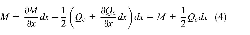
where Tc is the tension, Qc is the shear force of the section, mc is the mass per unit length of conductor,

Free body diagram of conductor element.
The torque M can be deduced from the beam bending theory and expressed as equation (5)

where Ec is the equivalent Young’s modulus for the steel–aluminum composite structure and Ic is the area moment of inertia.
By solving equations (3) to (5) jointly, one can get the differential equation of conductor vibration as equation (6)

Then, the vibration mode shape equation of conductor can be obtained as equation (7)
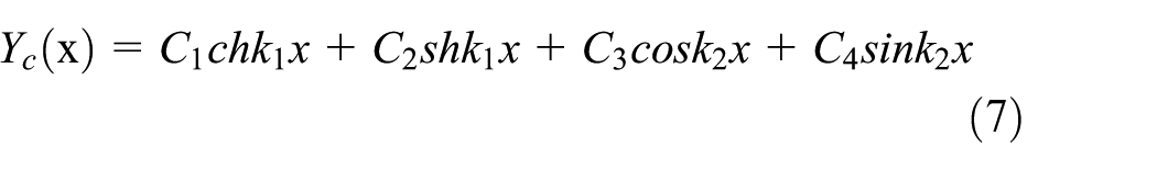
where k1 and k2 are the functions of Tc, Ec, Ic, mc, and fn, and C1, C2, C3, and C4 are the constants determined by boundary conditions and initial state of conductor.
The damping wires is usually a piece of steel-core-aluminum-stranded-conductor, which is attached onto the conductor and stands none tension. The energy dissipates by the friction of different strands when the damping wire vibrates with the conductor. The damping wire can be also assumed as a solid beam and its two suspension points vibrate with the conductor. The free body diagram of a section of damping wire is shown in Figure 2 and its kinetic equation of free vibration is expressed as equation (8)2,3

where Ew is the equivalent Young’s modulus of damping wire, Iw is the moment of inertia,

Free body diagram of damping wire (Qw1 and Qw2 are the shear force, θ1 and θ2 are the rotation angles, and M1 and M2 are the torques at two ends).
The vibration mode shape equation of the damping wire can be expressed as equation (9)

where D1, D2, D3, and D4 are the constants determined by boundary conditions and initial state of conductor, and b is the function of Ew, Iw, mw, and fw.
The Stockbridge damper is widely used around the world for aeolian vibration, which consists of the damper head, stranded steel wire, and fixed clamp, as shown in Figure 3. It can be assumed as a two-degree-of-freedom system and its free body diagram is shown in Figure 4, of which the equilibrium equation is expressed as equation (10)2,3

where M, C, and K are the system matrices of mass, damping, and stiffness, respectively, and

Structure diagram of the Stockbridge damper.

Free body diagram of the Stockbridge damper (yc and yh are the displacement of conductor and damper head,
The analytical models of conductor and damping devices provide useful information for the design of aeolian vibration suppression scheme for real lines and for physical model tests. However, in practice, due to the scatter of material property and the highly nonlinearity of the conductor–dampers–damping wires coupled system, laboratory test is still the main way for aeolian vibration suppression scheme design, optimization, and evaluation of large crossing transmission line section, especially for the UHV lines with little reference from open literatures and operating practice.
EBP for aeolian vibration
The design of aeolian vibration suppression scheme is based on the EBP, which says that the total wind energy input onto the conductor equals to the summation of the energy dissipated by conductor and damping devices, as expressed in equation (11) 14

where
According to previous studies on bundled conductors, the vibration intensity of eight-bundle conductors is about one-quarter of the single conductors, 25 due to the influence of spacers and wake flow effect, and a safety factor is then multiplied to ensure sufficient safety tolerance. Since that the eight sub-conductors of the UHV bundle are installed with the same aeolian vibration suppression scheme, in practice, only one sub-conductor is used for laboratory test first until the satisfactory scheme is found. Then, the selected scheme will be tested on the eight-bundle conductors for validation or modification to find the final efficient scheme, to ensure that the dynamic bending strains at all locations of the conductor under different frequencies are less than the maximum allowable value.
The three parameters,

where fc is the vibration frequency, D is the conductor diameter, Y is the vibration amplitude, and v is the wind speed.
The energy dissipated by the conductor,
Laboratory test for single sub-conductor aeolian vibration suppression scheme
Test setup for single sub-conductor aeolian vibration
Aeolian vibration test is based on the EBP. As shown in Figure 5, a segment of conductor is installed on the test span and the initial tension is adjusted to equal to the average operating tension. The two ends of the conductor are firmly fixed by heavy lumped mass block to stop the propagation of vibration wave. A vibration exciter is connected to the conductor and outputs a harmonic excitation force to simulate the aeolian vibration of conductor. Figure 5 demonstrates a typical aeolian vibration suppression scheme evaluation test for single conductors. When the damping devices are removed, it can be used for self-damping test of the conductor. The excitation frequency and intensity are adjusted during the test. The excitation power and vibration intensity of the conductor under the resonance state will be recorded. Then, calculation is conducted based on the measured results and input wind power curve.

Diagram of laboratory test for single conductor aeolian vibration.
The tests are conducted on the Bundled Conductor Vibration Comprehensive Test Table, with a total length of 150 m (the effective test length between two rigid blocks is 140 m), located in CEPRI, Beijing, China. The test table is designed according to IEEE guide on Aeolian vibration test 22 and has successfully completed most of the large crossing span Aeolian vibration tests in China, with the maximum real span length of 2756 m, as it validates the feasibility and reliability of the test facility and method. Key parameters are measured by commercial sensors, with the BK-2 force sensor for conductor initial (static) tension and BK-1 for dynamic tension measurement, CA-YD-107 accelerometer for displacement measurement, YE3816 strain meter for bending strain measurement, and HP 35660A frequency analyzer for power characteristic measure of vibration damper. All the measured data are processed by computer through internal software developed by CEPRI.
Self-damping test of sub-conductor
Self-damping characteristics of the single sub-conductor represent the relation between the energy dissipated by unit length of conductor and the vibration amplitude. It determines the ability of vibration energy dissipation of conductor, that is, the term
A three-span UHV line section is used as case study, with the middle crossing span of 2000 m and two side spans of 700 m each. The AACSR/EST-410/150 conductor, the properties of which are listed in Table 1, is used as sub-conductors with a distance of 550 mm between two adjacent sub-conductors. To be noted, the conductor type and configuration of the case are the same as the first demonstration 1000 kV UHV project in China.
Physical properties of the conductor (Type: AACSR/EST-410/15).

The self-damping tests are conducted following the IEEE guide with power method. A hydraulic exciter is employed to force the conductor to vibrate at different resonant frequencies (RFs), as shown in Figure 5. When the vibration is steady, five different excitation powers of the vibration table are adjusted with the frequency kept constant. Then the forces, frequency, and powers of the excitation source; the vibration amplitudes of conductor; and powers transmitted to the conductor and dynamic bending strains at the fixed point are measured. Then, a total of 11 excitation frequencies are tested in this study, which covers the frequency range of aeolian vibration.
For simplicity, the measured self-damping results are processed and plotted in a double logarithmic graph in Figure 6, the fitting formula of which is expressed in the following form

where fc is the vibration frequency of conductor, Y is the double amplitude at antinodes, and

Self-damping curve of the conductor (Type: AACSR/EST-410/15).
It indicates from Figure 6 that self-damping of conductor increases with the vibration frequency, as means that more energy is dissipated for higher frequency vibration. Therefore, the conductor may have sufficient damping so that no damping devices are needed in the high-frequency range, and the low-frequency range needs to pay more attention.
Power characteristic test of vibration damper
Vibration damper is one of the key devices for large crossing span aeolian vibration suppression, where the input wind energy onto the conductor is dissipated by friction among the stranded wires as introduced in the “Analytical models of conductors and damping devices” section. The damping ability of vibration damper is positively related to the vibration speed of the clamp, and most energy is dissipated when it vibrates in RFs. Power characteristic is the essential parameter used for the structure design and damping ability evaluation, and installs location selection of vibration dampers, as can be obtained by laboratory test. In this study, the test is conducted on the D-300-3 vibration electrical table following the national standard procedure of China, 26 which is also consistent with the International Electrotechnical Commission (IEC) guide. 27
During the test, the symmetric Stockbridge vibration damper (Type: FD-6/47) for UHV lines is firmly fixed on the test table, excited by harmonic force with a constant speed of 7.5 m/s. The test frequencies are in the range of 5 ∼ 105 Hz, with a linear scanning speed of 0.2 Hz/s. A total of three damper samples are tested, and the measured RFs and DPs (dissipating powers) of the vibration damper are listed in Table 2.
Measured RFs and DP of the vibration damper (Type: FD-6/47).

RFs: resonant frequencies; DP: dissipating power.
Table 2 shows that the scatter property of the measure results is in the required range at the RFs and it can be used for UHV aeolian vibration suppression. It is found in practice that the damping ability of vibration damper will decrease after longtime service, so it is common to use a combination of vibration dampers and damping wires for aeolian vibration suppression of large crossing transmission line spans, to keep the vibration intensity in a low level.
Evaluation test of aeolian vibration suppression scheme for single sub-conductor
The aeolian vibration suppression scheme and excitation output for the eight sub-conductors in the UHV bundle are same, wherefore the evaluation test can be done first only on one sub-conductor to get the optimal aeolian vibration suppression scheme and then be validated or modified by the test on the eight-bundle test span.
The test is based on the self-damping test of single sub-conductor in the “Self-damping test of sub-conductor” section, of which the same test span as Figure 5 is used but with damping devices installed at one end of the span. Larger excitation powers are needed than the self-damping test, for the damping device may dissipate more energy. The maximum dynamic bending strains around the suspension clamp, measured at different frequencies in self-damping test, are plotted in Figure 7. It indicates in Figure 7 that most of the maximum dynamic bending strains exceed the maximum allowable value (120 µε), when no aeolian vibration suppression scheme is used. Therefore, it is impulsive to design and install proper suppression scheme to keep the vibration in an acceptable level. According to previous studies and engineering practice, two types of schemes are proposed for comparison: the first one only uses vibration dampers and the second one employs a combination of vibration dampers and damping wires, as shown in Figure 8.

Frequency response curves with various aeolian vibration suppression schemes for single sub-conductor (MAS: Maximum Allowable Strains; NDD: None Damping Devices).

Diagram of various aeolian vibration suppression schemes: (a) suppression scheme 1, with vibration dampers only, and (b) suppression scheme 2, with both vibration dampers and damping wires.
From Figure 7, it shows that the excessive dynamic bending strains mainly occur at the low- and middle-frequency range, while the self-damping of conductor is sufficient to damp out the vibration energy at high-frequency range. Besides, the vibration occurring at low frequencies is easier to be transmitted to the span end section than that at high frequencies. This means that main attention should be paid to suppressing of vibration at low frequencies, so vibration dampers with low natural frequencies and damping wires with larger laces and less peeling strands are used to achieve expected results.
The installation location of vibration damper can be calculated from (14)

where
As a result, four Stockbridge vibration dampers (Type: FD-6/47) are used for suppression scheme 1, while three Stockbridge vibration dampers and a length of 15 m damping wires (Type: LGJ-630/45) are used for suppression scheme 2, with detailed configuration shown in Figure 8.
The maximum dynamic bending strains around the suspension clamp and damping wire clamps, measured at different frequencies, are shown in Figure 7 for the two schemes. It shows that the maximum dynamic bending strains are greatly reduced after installation of damping devices. Generally, the two schemes have similar suppression effect, with scheme 1 slightly better than scheme 2. By fitting the measure data, the relation between the DP of suppression schemes and vibration amplitude at antinodes can be obtained and expressed as equation (15)

where fc is the vibration frequency of conductor, Y is the double amplitude at antinodes, and
A further investigation of the test results shows that, for scheme 1, the vibration amplitude of the first damper close to span center is larger than scheme 2, which may greatly reduce the suppression performance after longtime vibration. Therefore, scheme 2 with a combination of vibration dampers and damping wires is recommended, due to its steady performance for longtime service. Besides, scheme 2 can be further improved as follows: if all the concerned dynamic bending strains meet the requirement only with slightly large amplitude occurring at equilibrium points, optimization can be done by increasing the number of damping wire laces and vibration dampers; if the bending strains exceed the safe value only at several frequencies or locations, optimization can be done by adjusting the number and type of damping wire laces.
Experimental validation of aeolian vibration suppression scheme for eight-bundle conductors
The aeolian vibration of bundled conductor is influenced by the restriction effect among different sub-conductors and the damping of spacers, so the vibration intensity of bundled conductor is slightly weaker than that of single conductor. As a result, there is no need to design and install particular aeolian vibration suppression scheme for ordinary spans with bundled conductors, except for spacers, while it is impulsive for all the large crossing spans.
Test setup for eight-bundle conductor aeolian vibration
Although the eight sub-conductors of the UHV bundle are equipped with the same aeolian vibration suppression scheme, the vibration of the eight sub-conductors is not identical due to the influence of spacers and the scatter of physical properties among the sub-conductors. Therefore, the selected aeolian vibration suppression schemes for single sub-conductors need to be validated or modified for the eight-bundle conductors experimentally.
The test setup for eight-bundle conductor aeolian vibration, shown in Figure 9, is more complicated than that in the “Test setup for single sub-conductor aeolian vibration” section for single conductors. It is required that the tension of the eight sub-conductors in the test is generally equal to one another, with an acceptable error of 1%, to ensure the balance and symmetricity of the bundle vibration.
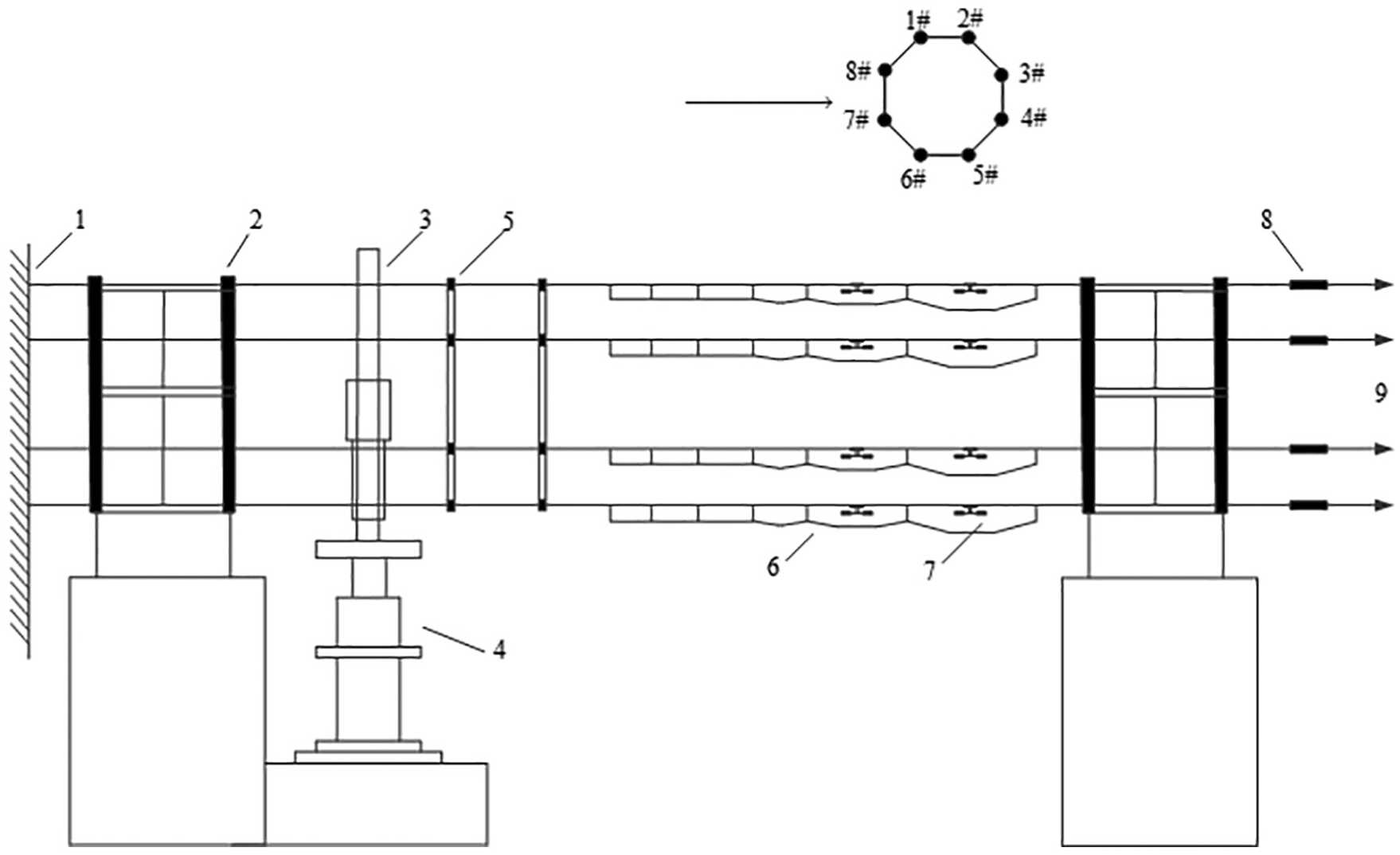
Diagram of laboratory test for eight-bundle conductor aeolian vibration (1. Fixed end, 2. Positioning plate, 3. Excitation frame, 4. Excitation table, 5. Spacer, 6. Damping wire, 7. Vibration damper, 8. Tension sensor, 9. Tensioning end).
An excitation frame, transmitting the energy from the excitation source to each sub-conductor, is designed first. It is required that the excitation force should be evenly distributed to the eight sub-conductors through the frame, and the frame should be as light as possible to minimize its influence on the system. The balance ratio is a parameter used to evaluate the performance of the excitation frame for bundled conductor test, as is defined in equation (16)

where

The eight-bundle excitation mechanism (a) photo of the frame alone and (b) the excitation frame connected to excitation table.
The rigid block is redesigned to accommodate the eight-bundle conductors, which can stop the propagation of the vibration energy. Two positioning plates are designed and connected to the rigid block, which fix the ends of each sub-conductor and ensure the relative positions of each sub-conductor ends, as shown in Figure 11.

The rigid block with two positioning plates of the test span: (a) side view and (b) upward view.
To validate the applicability of aeolian vibration suppression schemes of single sub-conductor in the “Laboratory test for single sub-conductor aeolian vibration suppression scheme” section to the UHV eight-bundle conductors, the bundled conductors with scheme 1 and scheme 2 are installed on the above-mentioned test span, respectively, as shown in Figure 12. The tests are conducted following the same procedures for single conductor. The dynamic bending strains at concerned locations (around suspension clamps, spacer clamps, damping wire clamps, and vibration damper clamps), antinodes amplitudes of each sub-conductor, and excitation powers are measured.

The rigid block with two positioning plates of the test span: (a) with scheme 1 and (b) with scheme 2.
Validation of aeolian vibration suppression scheme on eight-bundle conductors
To verify the efficiency of the excitation frame and the test system on keeping the balance and symmetricity of the bundle vibration, the maximum antinode amplitudes of each sub-conductor of scheme 1 are recorded and listed in Table 3. It shows that the balance ratios of different test scenarios are within the range of 83.3% to 96.3%, which meet the requirement of no less than 50% for the tests, that is, the test setup is effective and reliable.
Measured antinode vibration amplitudes of sub-conductors for aeolian vibration suppression scheme 1.

The frequency response curves of scheme 1 and scheme 2 are plotted in Figure 13. It indicates from Figure 13 that both of the two schemes can keep the maximum bending strains at different frequencies in a safe range. However, scheme 2 with a combination of vibration dampers and damping wires is recommended for the UHV eight-bundle conductors used for large crossing span, due to its steady performance for longtime service, compared with scheme 1.
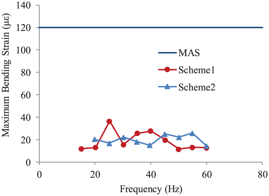
Frequency response curves with various aeolian vibration suppression schemes for eight-bundle conductors.
To be noted, this study only reports the tests for the suspension (middle) span of the mentioned UHV large crossing line section, and the tests for the tension (side) spans are also conducted at CEPRI, of which the procedures and conclusions are the same as the suspension (middle) span.
Conclusion
This article focuses on the aeolian vibration characteristics and suppression methods for the eight-bundle 1000 kV UHV conductor of large crossing span. The analytical model of conductor, vibration damper and damping wire, and the EBP are introduced, which show the key factors influencing aeolian vibration of conductor and provide useful information for the experimental study. Then, a series of laboratory tests are conducted to obtain the self-damping characteristics of conductor and energy dissipation power of vibration damper, and two aeolian vibration suppression schemes are evaluated and compared experimentally. Finally, the two aeolian vibration suppression schemes are validated on a designed eight-bundle conductor test span, and the optimal scheme is selected. The following conclusions can be drawn from this study:
Analytical analysis can only provide limited information, while experimental method is the practical way for vibration suppression scheme design and evaluation, especially for large crossing span transmission lines using bundled conductors.
The self-damping of conductor is large enough to damp out large proportion of high-frequency vibration energy for the studied case, as means that efforts of aeolian vibration suppression scheme should be put mainly on the vibration occurring in medium- and low-frequency range.
The schemes proven to be effective on the single conductor case are also sufficient to suppress the Aeolian vibration of the UHV eight-bundle conductor span.
Two proposed schemes, one with vibration dampers only and the other one with both vibration dampers and damping wires, can both greatly reduce the maximum bending strains of the single and bundle conductors, while the latter is preferred and recommended for the large crossing span transmission lines, for its excellent long-term service performance.
This study illustrates standard procedures for UHV eight-bundle conductor aeolian vibration suppression scheme design, test, and evaluation, and useful conclusions are summarized, as it is essential to ensure the aeolian vibration in a safe level and to avoid fatigue failure of the conductors and related components of transmission lines. This study also provides helpful reference for aeolian vibration suppression of other types of bundled conductor lines, to improve the mechanical security of transmission lines.
Footnotes
Acknowledgements
The technical personnel and colleagues in the Department of Transmission Line Conductor and Fittings at China Electric Power Research Institute are acknowledged for their work in the tests and insightful discussion about the research.
Handling Editor: Xiaoxiao Han
Declaration of conflicting interests
The author(s) declared no potential conflicts of interest with respect to the research, authorship, and/or publication of this article.
Funding
The author(s) disclosed receipt of the following financial support for the research, authorship, and/or publication of this article: This research was supported by National Key R&D Program of China (Grant 2018YFC0809400) and the Beijing Natural Science Foundation (Grant 8174079).