
Abstract
In this study, Taguchi method is used to investigate the effect of critical process parameters of investment casting on dimensional variations of thin walled, complex geometrical stainless steel component. A set of experiments have been conducted to calculate shrinkages which is a measure of dimensional variation. The process parameters considered here are number of ceramic coats, pouring time, pouring temperature, and casting cooling rate. The signal-to-noise ratio and analysis of variance are used to study the influence of these parameters on shrinkage. Optimized condition for reduced shrinkage deviation can be obtained by selecting lower number of ceramic coats, faster and laminar metal pouring, lower superheated metal temperature, and faster cooling rate. Analysis of variance reports that the number of ceramic coats is the most significant parameter with more than 80% contribution whereas other parameters are insignificant. Investigation results also indicate that constraint dimension (width) has 25%–27% higher dimensional variability than non-constraint dimensions (height) for the selected component.
Introduction
Investment casting (IC) is widely preferred process among all the precision casting process to produce components, having complex geometry, stringent tolerances, and excellent surface finish. The IC process offers extensive choice of cast metal and large range in size and shape of the component. In foundry, a thin-walled hollow rectangular component with varying thickness, is considered as a complex casting. Geometrical distortion is a major issue in such complex stainless steel casting due to large temperature gradient and high melting point. Distortion is nonconformance of measured casting dimensions from the specified drawing dimension. Major correction operations such as reworking of wax die and casting coining operations are required to bring the casting dimension in specified control limits. These additional correction operations increase lead time as well as additional tooling and labor cost. The IC process consists of multiple stages and process variability at each stage contributes to casting dimensions. Shrinkage at wax, mold, and casting stages plays major role in deciding the final casting dimensions. Wax shrinkage is one of the largest shrinkages in total shrinkage of component.
Several researchers1–3 have contributed their work in finding out influence of wax injection process parameters on dimensional stability of wax pattern. Morwood et al. 4 reported that usage of filled wax, lower temperature gradient, and rigid restraint offered by metallic core assures minimum shrinkage deviation of wax pattern. In mold stage, the base coat of ceramic mold is formed by zircon slurry and stucco. High melting point and very low coefficient of thermal expansion of zircon provides accuracy and consistency of mold dimensions as reported by Bates et al. 5 Mold thickness is controlled by applied number of ceramic coats on wax pattern. Singh et al. 6 and Kumar et al. 7 considered this factor along with other while studying rapid IC and hybrid IC.
Casting stage is having the maximum contribution and variability in total shrinkage which affects casting dimensions significantly.8–10 Okhuysen et al. 11 reported from survey-based study that dimensional discrepancies will potentially result when same set of tooling allowances has been used for different cast alloys to produce components. Harste and Schwerdtfeger 12 measured shrinkage of steel during solidification and subsequent cooling and confirmed the carbon content affects the shrinkage of steel. Effect of pouring temperature on dimensional accuracy has been studied by Farhangi et al. 13 and Seidu and Onigbajumo 14 reported that increase in temperature causes increase in thermal strain. The selection of pouring technique affects the metal temperature at pouring, viscosity, temperature distribution, and thermal stress in casting. 15 Singh et al. 16 examined the effect of metal composition, slurry layer combination, and pouring temperature on dimensional deviation of casting and informed that all the factors are significant. Kang et al. 17 attempted intensive cooling of riser by water spray which results in uniform temperature distribution and reduced residual deformation. Sabau 18 reported that in IC, mold configuration restricts air flow surrounding casting surfaces and affects the uniform cooling of mold. Distortions create inefficiencies throughout the casting process that can adversely impact lead times and generate considerable waste. 19 Control on casting dimensions improves foundry productivity significantly. 20 This research work is carried out by conducting a set of experimentation to study the effect of various process parameters at selected levels on dimensional accuracy of casting. To simplify and reduce the experimental work, several researchers6,16,21,22 have applied Taguchi technique. This research work also uses Taguchi approach to determine the contribution of parameters in dimensional variability. Shrinkage of the component has been compared with shrinkage of standard test piece from the same mould to find out dimensional deviation. Using Taguchi approach, optimized levels of the selected parameter have been recommended to improve the dimensional accuracy of casting. This reduces the requirement of additional correction operations thus increasing foundry productivity significantly. The study simultaneously compares the analysis of constrained and non-constrained dimensions.
Methodology and experimentation
The aim of this experimental research is to investigate the effect and identify the optimized condition for selected casting process parameters to improve dimensional accuracy of the IC component using Taguchi technique. The overall methodology for research work is illustrated in Figure 1 and described below.

Steps of Taguchi technique.
Details of the selected component
In this research work, a thin-walled hollow rectangular component with varying thickness has been selected as shown in Figure 2(a). This component has applications in various industries. The weight of casting is approximately 1.05 kg and the material used is stainless steel (CF8). The two critical dimensions of the component are inside width (66 ± 0.45 mm) and height (96 ± 0.55 mm) of a rectangular cavity. The thickness of part (along Z direction) is 42 mm as shown in section B-B. The component has three isolated thick sections P, Q, and R in which hot spots get developed during solidification of casting. To remove these hot spots, three independent feeds are required to be attached to the component as shown in Figure 2(b). The feed pads at P and Q location influences and restricts the normal and free solidification of the “width” hence considered as constrained dimensions while as “height” dimensions are free to shrink referred as unconstrained dimensions. Measurements were taken on both these dimensions (width and height) throughout the experiment.
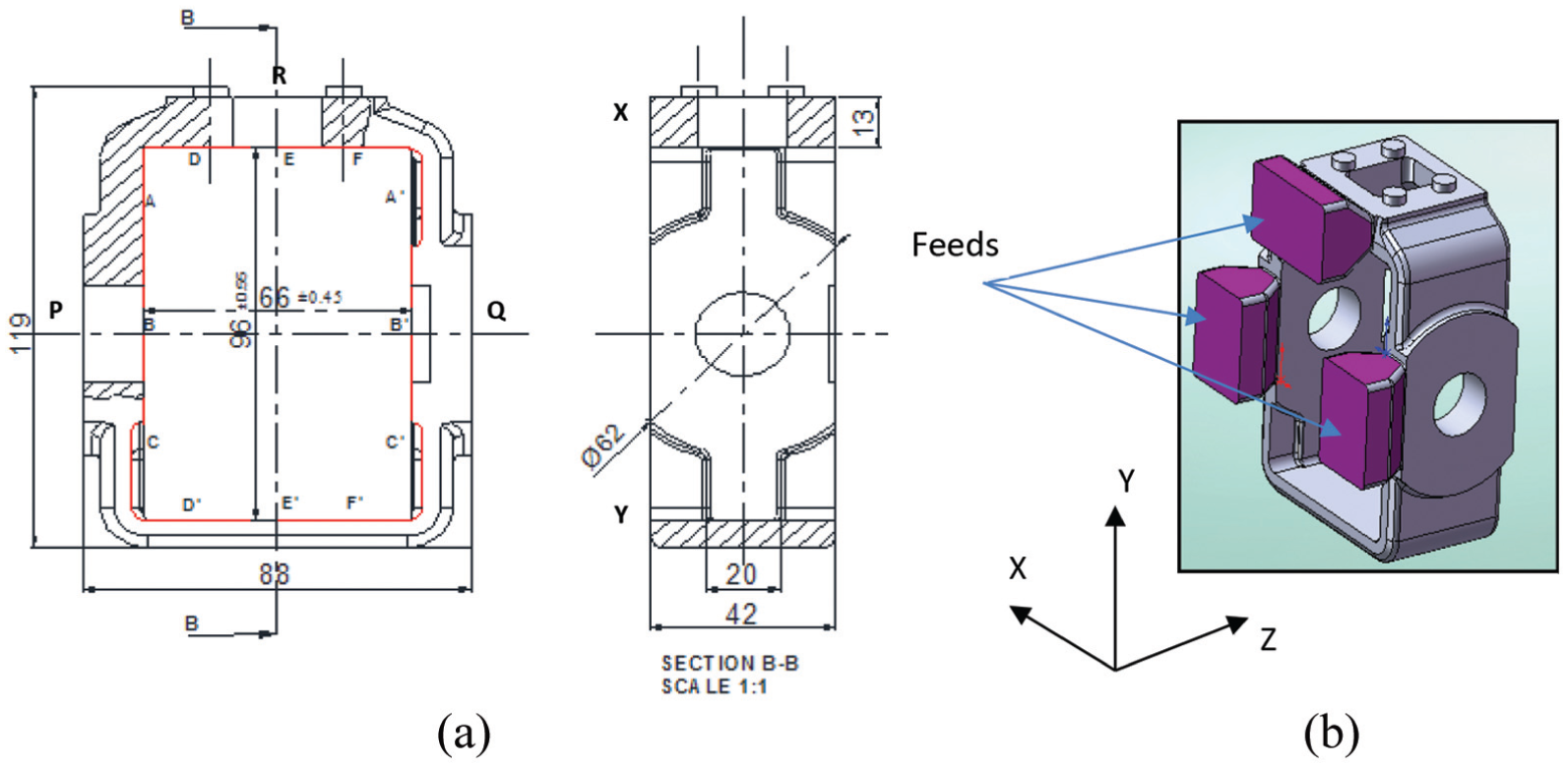
(a) Schematic diagram of component and (b) feeders of component.
Selection of process parameters
IC process consists of multiple stages and each stage is contributing to dimensional changes of component. Various process parameters at major stages of investment casting which affect the dimensional accuracy have been listed in Ishikawa (cause and effect) diagram as shown in Figure 3. These parameters can be grouped into four different stages wax, mold, casting, and post casting stages. At wax stage, composition of wax and wax injection process parameters such as pressure, temperatures, and holding time are influential. Use of filled wax and wax chill prevents excessive shrinkage at thick sections of the casting. Insertion of metallic spacer in ejected wax pattern helps to reduce deformation. Use of highly automated wax injection machine which provides precise control and monitoring of process parameters and results in consistent and accurate wax patterns. At mold stage, the mold composition, mold temperature number of coats, stucco size affects the mold dimensions. Number of ceramic coats significantly affects the thickness of mold and thus strength of mold thus selects as one of the parameters for Design of experiment (DoE). Major dimensional change occurs during solidification and cooling of casting at casting stage. Shrinkage occurs in three phases: liquid shrinkage, solidification shrinkage, and solid shrinkage. Thus, majority of the parameter has been taken from this stage except cast alloy composition as it is controlled by customer as per requirement of part. Thus, significant and controllable input parameters such as pouring temperature, pouring rate, and casting cooling rate along with number of ceramic coats are the four parameters selected for experimentation to study their impact on dimensional accuracy of casting. Two levels of each parameter have been selected for the present work and are given in Table 1 followed by brief description.
Number of ceramic coats: Thickness of mold is controlled by applied number of ceramic coats on wax pattern which depends on size and weight of the casting. Use of thin ceramic shell utilizes material efficiently and reduces process time but may bulge or leak during pouring and solidification. On the other hand, thick mold supports metallostatic pressure of hot molten metal during the casting process and avoids probability of leakage and bulging. Nine coats which are standard are considered for level 2 and seven coats for level 1.
Pouring technique: The molten metal has been poured in the hot ceramic mold either by ladle pouring or by furnace pouring. In the ladle pouring, metal has been transferred from furnace to ladle and then ladle to the hot mold by tilting ladle manually which takes approximately 10–12 s. In the furnace pouring, mold capacity and furnace melting capacity are equal and furnace is having tilting arrangement. Hot mold has been clamped on furnace top and complete charge (molten metal) is poured by controlled rotation of the furnace. This results laminar and steady flow with pouring time of 5–6 s. The pouring technique affects the mold filling time, viscosity, temperature distribution, and thermal stress in casting. Thus, selecting the ladle and furnace pouring as two levels.
Pouring temperature: In IC, the intricate shape component has been poured with superheated metal temperature which is generally kept above the melting temperature of the alloy to avoid the “not fill defect” in the casting. Metal pouring operation needs high coordination between the pouring operators. Time delay in pouring drops the melt temperature significantly which further affects casting quality. The standard temperature set by method study technique is 1590°C and by varying superheat degree to 1640°C, other level has been selected for cast metal (stainless steel alloy).
Casting cooling method: To avoid surface decarburizing of stainless steel casting, the top of the mold cup is sprinkled with exothermic flux immediately after pouring. This flux burns and generates large amount of heat and holds the mold top cup and hence the molten metal hot for longer duration. This happens in covered environment which restrict the air circulation and decrease the metal cooling rate to 10°C/min. The alternate method is allowing the mold to cool in open air without cover which increases the cooling rate to 20°C/min. To understand the effect of variation in cooling rate on casting dimensions, these two cooling methods (open and covered) have been selected for study.

Ishikawa cause and effect diagram for the dimensional accuracy of IC process.
Selected parameters and their levels.

Orthogonal array
In today’s competitive market, manufacturing industries have to produce quality products at reduced cost with smaller lead time. Taguchi’s orthogonal array is the most efficient tool which helps in reducing total number of experiments. In this work, the four process parameters namely number of ceramic coats, pouring time, pouring temperature, and casting cooling rate each at two levels have been considered. Selection of appropriate orthogonal array for selected parameters is the important step in Taguchi technique. Total degrees of freedom for each parameter when varied at two levels is 4. A two-level orthogonal array (L827) with eight experimental runs (degrees of freedom = 8–1 = 7) is selected for this research. Orthogonal array is the smallest possible design of combinations in which all the parameters are varied simultaneously and their effect and performance interaction can be examined concurrently. The array name (L827) indicates that it can use 7 factors at two levels. The number 8 represents total number of experiments to be conducted as shown in Table 2. In present case, each of the four factors has been varied at two levels and no consideration has given to interaction effect of the parameters. Thus, four factors have been assigned sequentially to first four columns of L8 orthogonal array while as remaining three kept unassigned as explained by Roy. 23
Orthogonal array L8(27).

IC procedure
As per the experimental layout shown in Table 3, casting trials were conducted. Filled wax is used for wax pattern. As per conventional IC process, ceramic mold is formed using zircon slurry and flour for primary coat and aluminum silicate for other coats for stainless steel casting. Conventional IC process has been described as follows:
Wax patterns have been injected using set wax injection pressure (30–40 kg/cm2), temperature (55°C–65°C), and holding time (60 s). Critical dimensions: width and height were measured on wax patterns at AA′, BB′, CC′ and at DD′, EE′, FF′, respectively, as shown in Figure 1. Eight wax assembly trees have been formed by attaching eight wax patterns, four on each side of vertical wax riser plate which represents eight casting trials as per L8 array. All wax patterns and tree assemblies have been numbered for identification as per designed trial.
The wax assemblies have been coated first with primary coat of zircon slurry at 120–140 s viscosity and the secondary coat of aluminum silicate having slurry viscosity as 50–60 s. Slurry viscosity has been measured using ford cup of size B. Each coat was followed by stuccoing. Number of secondary coats has been varied as per L8 array. These molds were then allowed to dry. The whole process has been carried out in humidity (45%–60%) and temperature (25°C) controlled environment and completed in 3–4 days. The dried mold had been taken to auto clave to remove wax from mold using steam of temperature 150°C at pressure of 10 bar. Mold was then sintered in oil fired furnace at temperature 1050°C–1100°C for 2 h which has been taken out of furnace just before pouring. The interval time between removal of mold from furnace and actual metal pouring is allowed up to 40 s. If delay is beyond 40 s, the mold is not poured and left unfilled as ceramic shell is thin wall construction which cools rapidly. Delay in pouring reduces the temperature of preheated mold and causes early solidification of metal before reaching to the intricate corners of each casting. This will result to cold shut and no fill defects in casting.
Cast metal of low carbon, high alloy, austenitic stainless steel of required composition has been melted to pouring temperature and poured in preheated molds. Molds were filled by hot molten metal having different pouring temperatures by changing superheat degree in corresponding mold using two different techniques and then allowed to cool in open air or in covered condition as per L8 array design.
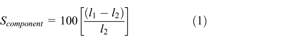
Critical dimensions of width and height were again measured on 64 castings each dimension at three specified locations as shown in Figure 1 from which average width and height of the component has been calculated. Linear shrinkage for both the dimensions of the selected component has been calculated as per equation (1). Where
Shrinkage deviation have been calculated by comparing shrinkage of the component with standard shrinkage of the metal at three locations. These shrinkage deviations R1,R2,R3 represent the measure of dimensional accuracy and considered as the responses for L8 orthogonal array (Table 2). These values along with average shrinkage deviation are shown as response values in Tables 4 and 5

Expt. layout after assigning the parameter values in orthogonal array.

Percentage shrinkage deviation for width dimensions.

S/N: signal-to-noise.
Percentage shrinkage deviation for height dimensions.

S/N: signal-to-noise.
Results and discussion
After conduction of experiment and measurement of shrinkage at three locations, the collected data have been analyzed by means of calculating signal-to-noise (S/N) ratio. The means analysis and S/N ratio analysis plot has been plotted using Minitab software to determine optimized condition of process parameter. The analysis of variance (ANOVA) has been calculated using statistical formulas to find out the contribution of each parameter. The range within which the true value of estimated mean will lie has been calculated by finding confidence interval at 95% significance level. The detail analysis of ceramic coats which is the most significant factor has been done by varying numbers of coats in small steps to determine the effect on shrinkage of critical dimensions of component.
S/N ratio analysis
For experimentation with repetitions, use of S/N ratio permits to determine the variance index. The greater the value of this index, the smaller the product variance. The objective of the study is to reduce the shrinkage variation of component from standard value. Thus, the S/N ratios for this work have been calculated on the basis of “lower is better” approach which is logarithmic function based on mean square deviation (MSD) and given by the following equation
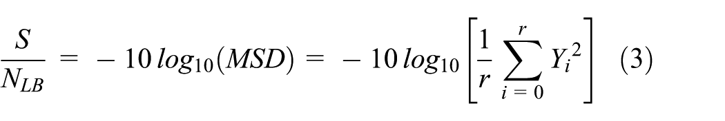
where
Main effects of selected parameters
Specially designed L8 orthogonal array facilitates to find out the main (average) effect of factors by combining the similar levels of factors from each trial. The main effect plot of means and S/N ratio for selected casting process parameters: number of ceramic coats, pouring technique, casting cooling method and pouring temperature is shown in Figures 4(a), 4(b) for width and 5(a), 5(b) for height dimensions. The plots for both the critical dimensions indicate that as the number of ceramic coats (A) increases from seven (7) to nine (9), shrinkage deviation increases significantly.

(a) Main effects plot for means of width shrinkage deviation. (b) Main effects plot for S/N ratio of width shrinkage deviation.

(a) Main effects plot for means of height shrinkage deviation. (b) Main effects plot for S/N ratio of height shrinkage deviation.
Ceramic mold undergoes heating and cooling stages such as dewaxing, preheating, and pouring which may affect the casting dimensions. Ceramic material used for mould is thermally stable. Thus mould shrinkage/expansion is considered as negligible. The shell is thermally stable in autoclave as temperature is 150°C, but it may crack due to thermal expansion of wax in the mold, if autoclave furnace takes longer time to build the steam pressure. Thermal coefficient of expansion of ceramic is negligible as compared to the metal; hence, the shell will constrain the free shrinkage of cast metal. As the shell thickness increases, the constraint to free shrinkage of metal increases, thus increasing the shrinkage variation.
These results are in line with Singh et al. 6 The furnace pouring technique (B) provides minimum turbulence of metal flow as compared to ladle pouring technique thus resulting in reduced shrinkage deviation. The cooling method of casting (C) under covered sheet reduces the cooling rate, thus having high shrinkage variability as compared to open-air cooling. Higher pouring temperature results large temperature gradient which causes thermal strain and leads to more shrinkage deviation. This observation on temperature parameter is in line with Farhangi et al. 13
Estimation of optimized condition
In this experimental work, quality characteristic chosen for response (output) is “shrinkage deviation” and for improved dimensional accuracy, consideration is given as “smaller is the better.” From Figures 4(a) and 5(a), parameter levels with lower shrinkage deviation have been identified which represent optimised condition of parameters. However, higher levels from S/N ratio plot also represent the same optimised condition for selected parameters. These optimum levels indicate that the lowest shrinkage deviation (maximum dimensional accuracy) can be achieved by selecting seven number of ceramic coats (

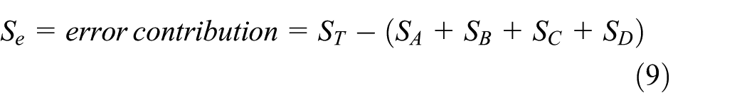
where
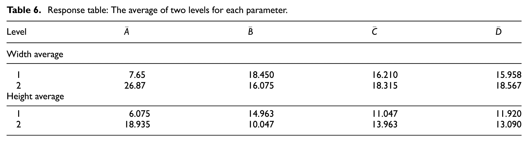
Response table: The average of two levels for each parameter.
Analysis of variance
ANOVA is carried out on the experimental results to distinguish between the significant and insignificant parameters and to determine the relative percentage contribution of each parameter which influences variability of results. Study of the derived ANOVA table aids to determine the parameters to be controlled for reduction in variability. Derived table has important terms such as degree of freedom, sum of squares, percentage contribution, F value, and P value and is obtained using following formulas

where the sum of squares provides a measure of the total variations present

where C.F. = T2/n; T is grand total of results =


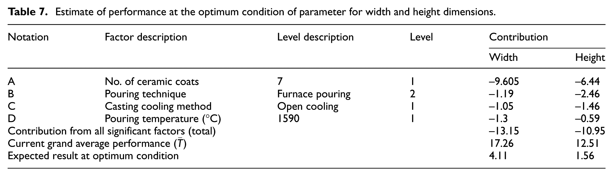
Percentage contribution (%) of each factor in result variation (shrinkage deviation) is derived from ANOVA analysis of experimental data using equations (5)–(12) and as shown in Tables 8 and 9.
Estimate of performance at the optimum condition of parameter for width and height dimensions.
Analysis of variance for width.

DOF: degree of freedom.
Analysis of variance for height.

DOF: degree of freedom.
ANOVA works on the variation from average values to predict the percentage contribution of the input parameters. The information about the contribution of parameter helps to differentiate between the significant and not significant parameters which controls the response function. Percentage contribution of each process parameter defines the power of the parameter to control the results. Observation of both Tables 8 and 9 indicates that the number of ceramic coats (A) is the most influencing factor as having the highest percentage contribution as 89.53% for width and 81.06% for height shrinkage deviation. The percentage contribution of other factors such as pouring technique (1.05, 11.75), casting cooling method (0.76, 4.06) as well as pouring temperature (1.33, 0.56) is less significant in width as well as height shrinkage deviation. Percentage contribution of all selected parameters is different for width and height. These differences are observed as width is constrained dimensions whereas height is non-constrained dimensions due to attached feeder on casting.
Error contribution for both the critical dimensions is 7.33% and 2.57% for width and height respectively. These are less than 10% which indicate that all the significant parameters have been considered in this study and no factor has been left out. It also represents that there exists negligible variation due to, uncontrollable factor, interaction of factors as well as variation in condition. The column F value indicates significance of the corresponding parameter by comparing with tabular F values. The smaller experimental F value compared to table values decides the factor to be pulled to get realistic effect of significant factors. Larger F value of the parameter represents that the variation in this parameter results large variation on experimental results.
Confidence interval
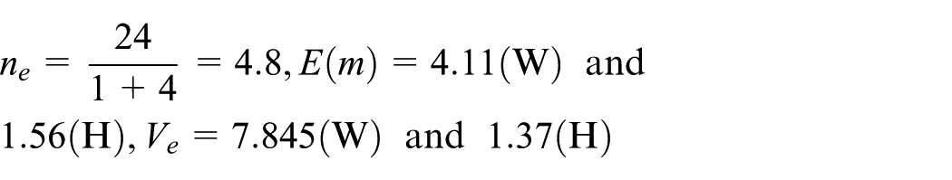
The true value of estimated mean will lie within a range, which has been calculated by finding confidence interval (C.I.) at specific significance level. If the estimate of the mean value of a set of observations is donated by

where
Confidence level is (


Confirmation trial
The experimental trial for predicted optimized condition of the parameter is essential if the optimized condition is not from the experimental design suggested by Taguchi technique. In this case, it is 1-2-1-1, that is,
Shrinkage analysis of most contributing factor
The number of ceramic coats is the most significant factor contributing in dimensional accuracy of the width as well as height dimensions. The impact of this factor has been studied by carrying out the few more trials at different coat levels as discussed below. In this work, seven ceramic molds were coated with different numbers of coats (4 to 10) for the selected component along with test piece. Figure 6 shows graph of number of coats versus mold thickness and percentage shrinkage. This indicates that as number of coat increases, mold thickness increases while as percentage shrinkage of test piece, width, and height of component decreases but gets stabilize after 10 coats. Increase in mold thickness constraints the free shrinkage of alloy during solidification and cooling as compared to thin mold. The height dimensions of the component follow the shrinkage path of standard test piece as is free from feeder constraint whereas width dimension has lower shrinkage value due to constraint offered by feeder.

Influence of number of ceramic coats on percentage shrinkage and mold thickness.
Conclusion
In this study, the impact of selected casting process parameters on dimensional accuracy of complex stainless steel casting has been studied using Taguchi method.
The optimum condition of casting process parameters results in high dimensional accuracy by reducing average shrinkage deviation of critical dimensions more than 50%. The selection of lower number of coats for ceramic mold, controlled metal pouring technique with sufficient superheat temperature and open-air cooling reduces shrinkage variation in casting.
The results report that the number of ceramic coats is the major factor toward achieving reduced shrinkage deviation as having contribution above 80% for both the critical dimensions. Other process parameters contribution observed as negligible.
Increase in number of coats on ceramic mold results the steep decrease in shrinkage of both the critical dimensions, width and height. Attached feeders on width constrain the free shrinkage of casting; thus, width results less shrinkage compared to height, thus more variability in width dimensions.
Footnotes
Handling Editor: Shun-Peng Zhu
Declaration of conflicting Interests
The author(s) declared no potential conflicts of interest with respect to the research, authorship, and/or publication of this article.
Funding
The author(s) disclosed receipt of the following financial support for the research, authorship, and/or publication of this article: The project has been funded under Technical Education Quality Improvement Program (TEQIP II) of Government of India, World Bank Assisted Project for Research and Development under Veermata Jijabai Technological Institute (VJTI), Matunga, Mumbai and experimentation support from Uni Deritend Ltd, Nasik, India.