
Abstract
The ultra-low-friction pneumatic cylinder has promoting applications in high-precision motion control and load simulator systems owing to its capability of attenuating stick-slip behavior at low speed and easily realizing accurate force at high speed. A pneumatic cylinder with an aerostatic bearing as its piston is recently proposed to achieve ultra-low friction. Two mathematical models that, respectively, consider one-dimensional flow and two-dimensional flow through the air film between the cylinder piston and the cylinder wall are developed to predict performance characteristics of the system working at different load conditions. The multiple design parameters are lumped into non-dimensional structural parameters and environmental parameters. Then, a constrained optimal design method is developed to achieve prior performance with smallest leakage flow rate for better dynamic response and appropriate radial load carrying capacity for supporting the floating piston itself. Performance comparison addresses the important influence of lumped non-dimensional parameters and unified assessments of two models for the ultra-low-friction pneumatic cylinder. The available optimal design parameters and achievable performances are indicated.
Introduction
Pneumatic cylinder is a significant component in pneumatic actuation systems, which has been widely used in various fields including industrial automation, 1 high-precision medical devices, 2 and robotics. 3 The friction force of the pneumatic cylinder is one of the most important factors that affect system performances. On one hand, stick-slip behavior will inevitably occur due to large discrepancy of dynamic and static friction, resulting in poor stability and low accuracy of positioning if the pneumatic cylinder is moving at a low speed. On the other hand, the response speed of the system will be limited due to large ratio of friction force to useful actuation force when the cylinder moves at high speed. Moreover, the friction force of the pneumatic cylinder will bring out great difficulties in high-precision tracking control as it possesses complex dynamics and is hard to be accurately modeled and effectively compensated.4,5 Usually, there are two methods for achieving low-friction. The first one is to design sealing structures of the cylinder for reducing friction. Therein, Belforte et al. 6 designed compressed air as lubricants in round grooves between the pneumatic support of the rod and the front chamber. FESTO Limited 7 presented Type DSBC-L with special grease and small friction materials. SMC Corporation presented Type MQQ serials with metal seal structure.8,9 Gao et al. 10 presented a pneumatic cylinder based on ultrasonic friction reduction. The second one is to employ air-floating technique for generating non-contact movement of the cylinder. Therein, Corteville et al. 11 utilized two air bearings with external supply source to support and guide the movement of the piston rod. Lu et al. 12 designed an air-suspending frictionless cylinder with aerostatic bearing as piston for precise constant pressure control of a zero gravity simulation. Airpel-AB 13 presented their air bearing cylinder that has air bearings with airflow effect around the specially shaped stainless steel piston to realize frictionless effect. For this type of ultra-low-friction pneumatic cylinder with air bearing, several studies have attempted to analyze the static and dynamic characteristics of aerostatic films based on Reynolds equation and small amplitude perturbation.14,15 The influence of structural parameters (such as sealing structures and throttle diameters) and time-varying surrounding parameters of a new-type frictionless pneumatic cylinder with an aerostatic bearing as its piston has been investigated through numerical solution of Reynolds equations with finite element model (FEM) or FLUENT simulation.16,17 Specially, the influence of non-constant discharge coefficient on the performance of aerostatic journal bearings has been presented through solving the Reynolds equation for compressible fluids. 18 However, the floating characteristics are usually analyzed under the working condition of constant atmospheric pressure in one chamber or both chambers. In fact, the pressures of two chambers are not working at atmospheric pressure but are usually dependent on load condition of system, which will have great influence on the static and dynamic performance of system. Moreover, because of the numerous parameters involved in performances of the ultra-low-friction pneumatic cylinder, the parameter design is complex, leading to the optimal design of the aerostatic bearing. The studies include a Pareto optimization method with a multivariable, multi-criteria problem 19 and a modified particle swarm optimization algorithm with single objective function, 20 and so on. However, the multi-objective optimization design of parameters will usually lead to conservative performances if weight coefficients of multiple objectives are not appropriately specified.
The contribution of this article focuses on the following aspects: (1) developing complete modeling of the ultra-low-friction pneumatic cylinder system in view of one-dimensional (1D) flow and two-dimensional (2D) flow through the air film; (2) evaluating the performance of the ultra-low-friction pneumatic cylinder working at different load conditions with lumped design parameters and assessing modeling errors for control design through performance comparison of two models; (3) presenting a constrained optimal design of the ultra-low-friction pneumatic cylinder, which could achieve clear parameter specification and non-conservative performances of cylinder applicable to different working conditions with practical constraints.
This article is organized as follows: section “Structure” presents the structure of the ultra-low-friction pneumatic cylinder with air bearing. Section “Performance modeling” presents the modeling of the ultra-low-friction pneumatic cylinder, respectively, in view of 1D flow and 2D flow through the air film. Section “Constrained optimal design” develops a constrained optimal design of the ultra-low-friction pneumatic cylinder fulfilling with practical applications; section “Simulation results and discussion” presents the simulation results of modeling and optimal design, and finally, conclusions are put forward.
Structure
A new type of ultra-low-friction pneumatic cylinder with air bearing as its piston is proposed recently, which can greatly reduce friction force generated from sealing components contacted with the piston and the cylinder wall in traditional cylinders.21,22 The structure of the ultra-low-friction pneumatic cylinder is shown in Figure 1. There is an air bushing assembled between the piston rod and the end cover of cylinder to guarantee small sliding resistance during moving. A custom-made floating piston with several throttle orifices and inner chambers is placed inside the cylinder. An air film exists between the piston and the cylinder wall. Several check valves are placed symmetrically at two sides of the floating piston to separate the inner chamber of the piston and the left or right chamber of the cylinder. When the pressure of the left chamber is higher than that of the right, the diaphragm spring of check valves at the left side of the piston will open and the right ones will close. Consequently, pressurized air goes into the inner chamber of the piston until a pressure balance is reached, and vice versa.

Structure of the ultra-low-friction pneumatic cylinder.
There are several throttle orifices distributed in m paths along axial direction and n divisions are evenly located at each path along circumferential surface of the floating piston, as seen in Figure 2. When the cylinder is working, the air is flowing from the inner chamber of the piston into the air film via the specific designed throttle orifices, which functions as an aerostatic bearing to realize non-contact movement between the piston and the cylinder wall.
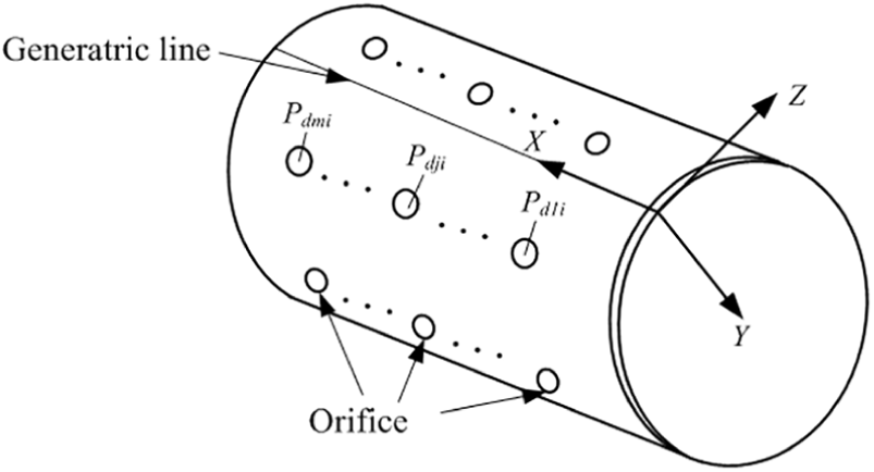
Structure of the floating piston inside the ultra-low-friction pneumatic cylinder.
Performance modeling
The floating characteristics of the piston inside the ultra-low-friction pneumatic cylinder (e.g. leakage flow rate and load carrying capacity) will have significant influences upon control performances in applications. For the performance modeling, following assumptions are considered:15,23
As the thickness of the air film is much smaller than its radius of the surface curvature, the surface curvature of the air film is neglected so that there is only translational velocity for the air film.
The pressure variation along with the air film thickness is neglected and thus the density and viscosity of the air film are invariant.
The inflow and outflow through the air film are regarded as isothermal process since the Reynolds number in air film is very small.
The inertia force due to the acceleration of the air film and the centrifugal load as well as the body force due to the gravitational and magnetic load acting on the air film are small enough to be neglected.
Pressure distribution in 1D flow
The dominant flow in the air film between the floating piston and the cylinder wall is along the axial direction from high-pressure side to low-pressure side, as shown in Figure 3.
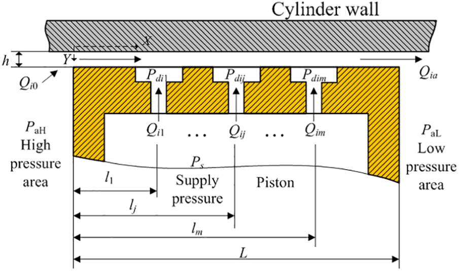
One-dimensional flow in the air film.
The Reynolds equation in 1D flow is given by

The boundary condition of equation (1) is given by
From equations (1) and (2), the velocity along axial direction is obtained

When the cylinder is in steady state, the flow rate of each division in the air film is given by

where i = 1, …, n and j = 1, …, m.
According to isothermal characteristics of ideal gas, the following equation is satisfied
Substituting equations (3) and (5) into equation (4) and assuming U0=0, the flow rate is
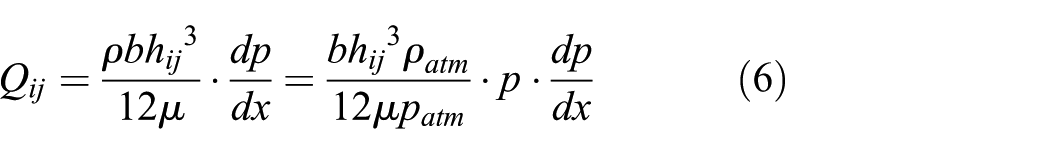
The integrals of equation (6) can be obtained through separating variables of pressure and flow rate, and then, pressures (p1, p2) at two positions (x1, x2) along axial direction in the air film can be obtained
Therefore, the pressures and flow rates of orifices for the ith division satisfy the following equation

Pressures of two chambers satisfy the following static equilibrium equation

The flow rate through each throttle orifice is 24

where Ps = PaH, kij is a pressure ratio given by

Therefore, the outside pressure and flow rate through each orifice at the ith division (Pdij and Qij) can be solved through combining equation (10) (m equations) and equation (8) (m + 1 equations).
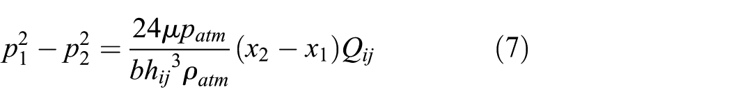
Suppose that the pressure in the air film along the adjacent orifice path is evenly distributed, the pressure distribution in the air film can be obtained as follows
Pressure distribution in 2D flow
The model of the ultra-low-friction pneumatic cylinder based on 1D flow above does not consider the flow rate along circumferential direction in the air film. In fact, there is small flow rate along circumferential surface of the piston, as shown in Figure 4 where the surface of the piston was unfolded when ignoring its surface curvature effect. In order to obtain more accurate insight into floating characteristics of the piston, a mathematical model that considers 2D flow (i.e. both axial flow and circumferential flow) will be developed.

Two-dimensional flow in the air film.
Differential equations of pressures in the air film
The continuity equations for the flow in the air film is

The flow dynamics of air particles at small Reynolds numbers satisfies

The boundary condition and flow rate along the X direction can be given by equations (2) and (4), respectively. And, the boundary condition of the Z direction is given by

Then, the flow rate of the Z direction is given by

Substituting equations (3) and (16) into equation (13), the Reynolds equation of hydrostatic piston is given by

where
In application, the magnitude of different dimensional variables can be much large. For example, the air film thickness is usually in the micrometer range. However, the piston diameter and the piston length are usually in millimeter range and are not the same order of magnitude with the air film thickness. As such, the dimensionless form of Reynolds equation of hydrostatic piston (i.e. equation (17)) is considered so that all necessary factors are allowed to be in the same order of magnitude to avoid data overflow and truncation errors

With dimensionless parameters being given by

where
At steady state, the variables

Define

Calculation of boundary conditions
It is difficult to obtain pressure distribution in the air film through analytical solutions of equation (21). Therefore, numerical solution is applied with partial differential equation (PDE) tools of MATLAB. According to the planar graph of unfolded floating piston shown in Figure 5, the boundary conditions are given as follows
Condition of low-pressure boundary:
Condition of high-pressure boundary:
Condition of orifice boundary:
Condition of periodic boundary:
Condition of load state:

Planner graph of the unfolded floating piston.
Except the orifice boundary, the other boundary conditions above are easy to be specified. In fact, the outside pressure of the orifice could be determined by the flow rate equilibrium condition explained as follows.
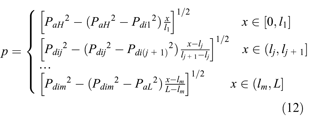
Consider an orifice area whose center is a single throttle orifice, as shown in Figure 6, the inflow through the orifice is given by equation (10) and the outflow through the orifice consists of flow rates along four directions, that is

where the flow rates along the X and Z axes can be obtained through the integrals of the air film velocity
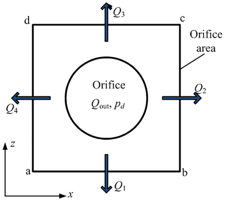
Orifice area of the floating piston.
The flow rate equilibrium condition is satisfied for the orifice area, that is

According to equations (22) and (10), the inflow and outflow through the orifice are, respectively, monotonic increasing and decreasing function of the outside pressure of orifice within the allowable supply pressure, as shown in Figure 7. Therefore, a numeric solution of the outside pressure of each orifice satisfying flow rate equilibrium condition is calculated through a variable step size method with a relative accuracy. 25 Finally, the diagram of iterative calculation of 2D flow modeling is given in Figure 8.

Inflow and outflow through an orifice.

Diagram of iterative calculation of 2D flow modeling.
Static performance of floating characteristics
When the ultra-low-friction cylinder is working at steady state, the static performances of floating characteristics can be evaluated by the following two performance indexes.
Leakage flow rate
According to continuity law of mass flow, the flow rate in the ith division Qia can be given by

And, the total leakage flow rate of the piston can be given by

Radial load carrying capacity
The center pressure of each grid area in Figure 5 can be calculated through interpolation method from outside pressure of two adjacent orifices (Pdij). Thus, the total radial load carrying capacity is the summation of force applied in the grid area

where Pcij, Acij, and θij are the center pressure, effective area, and position of each grid area at ith row and jth column, respectively.
Lumped design parameters
There are a lot of design parameters relevant to piston size (such as piston diameter, piston length, orifice diameter, length between the orifice center and the side of piston) and working conditions (such as load mass and supply pressure) as listed in Table 1. These parameters have coupling effects upon cylinder performances and need to be appropriately designed in various applications. For convenient insight in design, the parameters are lumped into non-dimensional forms regardless of physical size and are classified into structural parameters and environmental parameters, as defined in Table 2.
Default parameters of the ultra-low-friction cylinder.

Non-dimensional design parameters.

Pressure distribution in the air film
Figure 9 shows the pressure distribution based on 2D model with MATLAB PDE tools. As seen, the outside pressure of the orifice is slowly decreasing at high-pressure area and then significantly decreasing along axial direction when the pressure approaches to low-pressure area. And, it is noted that the outside pressure of the orifice is symmetric along circumferential direction. Thus, it is enough to take half of division numbers of floating piston (i.e. i = 1, …, 4) for assessments of pressure distribution.

Pressure distribution in air film with 2D model.
The pressure distribution in the air film based on 1D flow model and 2D flow model is shown in Figure 10. It is indicated that (1) there is small discrepancy of the outside pressure of the orifice between 1D flow and 2D flow models (less than 3%), while the pressure distribution of two models exhibits similar tendency along axial direction. (2) There are much more obvious pressure peaks around orifices with 2D flow model than with 1D flow model as the continuous orifice boundary is considered for more accurate estimation of pressures in 2D model.

Pressure distribution in the air film with 1D flow and 2D flow models.
Constrained optimal design
In order to achieve satisfactory performance suitable for various application requirements, a constrained optimal design for the ultra-low-friction pneumatic cylinder with multiple design parameters is proposed next.
Usually, there are some constraints dependent on the applications, such as the size level of floating piston, the limitation of volume due to assemble requirements, the available supply pressure, and different load masses. In addition, it is considered that the radial load carrying capacity should be large enough to suspend the floating piston for guaranteeing ultra-low-friction effect. That is, when the cylinder actuator is working at horizontal state, the radial load carrying capacity is required to be larger than the piston weight. And, when the cylinder actuator is working at vertical state, the radial load carrying capacity is required to be larger than the friction force possibly coming from slipping moving between the cylinder wall and the piston. As such, the optimization problem can be converted into minimizing leakage flow rate Qa subject to certain constraints that include sufficiently large radial load carrying capacity and limited volume requirements under specific working conditions in applications. The optimization formulation can be written as follows

where
The non-dimensional bounds and initial values of design parameters can be easily specified regardless of piston size, as listed in Table 2. The genetic algorithm (GA) is originally used to solve the optimization problem for finding the global minimum optimal performance subject to constraints. However, the efficiency of GA method is not satisfactory. In an attempt to catch the global optimum point with efficient calculation, an inbuilt optimization methodology in MATLAB known as “Globalsearch” method together with “Multistart” method is executed to achieve the optimal performances and parameters. 25
Simulation results and discussion
Next, the performance of the ultra-low-friction pneumatic cylinder with air bearing working at different load conditions will be evaluated through numerical simulations of above models and the optimal design results will be presented.
Performance comparison with two models
The performance of the cylinder with different lumped non-dimensional parameters at steady state under different load masses is investigated in the followings.
Different orifice diameter ratios
Figure 11 shows static performances along with orifice diameter ratio. As seen, the performances predicted by 1D flow model and 2D flow model achieve similar tendency. The radial load carrying capacity is increasing at small orifice diameter ratio and decreasing along with the increase in the orifice diameter ratio, while the leakage flow rate is always increasing along with the increase in the orifice diameter ratio. The peak of radial load carrying capacity appears when the orifice diameter ratio is 0.003 ∼ 0.004. It is obvious that radial load carrying capacity and leakage flow rate are increasing with the increase in the load mass.

Static performances along with orifice diameter ratio: (a) radial load carrying capacity and (b) leakage flow rate.
Different average thickness ratios
Figure 12 shows static performances along with average thickness ratio. As seen, there is similar tendency of performances between 1D flow model and 2D flow model. The radial load carrying capacity is increasing at small average thickness ratio and decreasing along with the increase in the average thickness ratio, while the leakage flow rate is always increasing along with the increase in the average thickness ratio. The peak of radial load carrying capacity appears when the average thickness ratio is 0.0003 ∼ 0.0005. Specially, the leakage flow rate increases dramatically when the average thickness ratio is larger than 0.0006, indicating that it is not appropriate to set too large average thickness. As expected, the radial load carrying capacity and leakage flow rate are increasing with increase in the load mass.

Static performances along with average thickness ratio: (a) radial load carrying capacity and (b) leakage flow rate.
Different orifice position ratios
Figure 13 shows static performances along with orifice position ratio. As seen, there is a small discrepancy of performances between 1D flow model and 2D flow model while the tendency of predicted performances is similar. The radial load carrying capacity and the leakage flow rate have small variation along with the orifice position ratio. Specially, the leakage flow rate is slightly decreasing along with the increase in the orifice position ratio, indicating that the location of orifice might have small influences upon available performances.
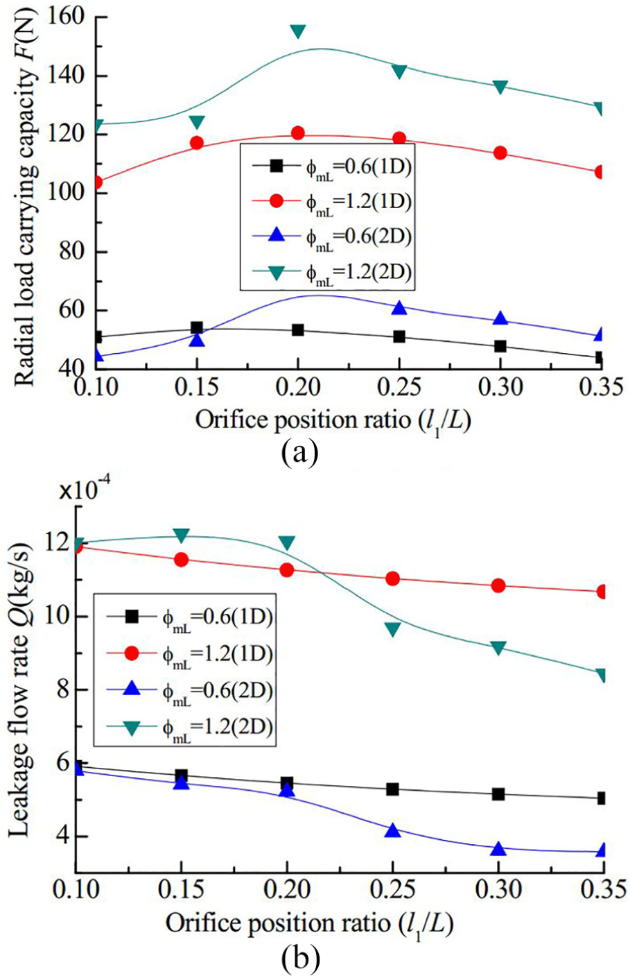
Static performances along with orifice position ratio: (a) radial load carrying capacity and (b) leakage flow rate.
Different length–diameter ratios
Figure 14 shows static performances along with length–diameter ratio. As seen, there is small discrepancy between 1D flow model and 2D flow model while the tendency is similar. The radial load carrying capacity is linearly increasing along with the increase in the length–diameter ratio, and the leakage flow rate is almost linearly decreasing with the increase in the length–diameter ratio. It is indicated that appropriate length–diameter ratio is necessary for achieving both large load carrying capacity and small leakage flow rate.

Static performances along with length–diameter ratio: (a) radial load carrying capacity and (b) leakage flow rate.
As seen from the performance comparison, there is small discrepancy between 1D flow and 2D flow models for the ultra-low-friction pneumatic cylinder, indicating that both of two models can achieve unified assessment of performances. On one hand, the 2D model is more capable of predicting system behavior in simulation as it considers more accurate flows in modeling. On the other hand, it is suggested that the 1D flow model could be conveniently utilized in control design or optimal design as the modeling errors of system could be easily assessed and compensated in implementation.
Optimization results
The results of the proposed constrained optimal design of the ultra-low-friction pneumatic cylinder along with different length–diameter ratios are presented in Figure 15. And, the optimization result at specific length–diameter ratio is given in Table 3. As seen, the achievable leakage flow rate is decreasing with the increase in the length–diameter ratio, indicating that large length–diameter ratio is helpful to decrease leakage flow rate. Meanwhile, the radial load carrying capacity is always slightly above the expected value (Fload = 120 N) for guaranteeing certain load capacity in applications. As seen from Figure 15 and Table 3, the optimal design parameters are dependent on length–diameter ratio within their permissible ranges. Specially, the average thickness ratio is obviously changed with the length–diameter ratio, indicating its major influences upon the available performances.
Optimization results at specific length–diameter ratio.


Optimal results along with length–diameter ratio: (a) radial load carrying capacity, (b) leakage flow rate, and (c) Optimal design parameters.
Conclusion
Two mathematical models of a ultra-low-friction pneumatic cylinder with air bearing that takes account on 1D flow (i.e. axial direction) and 2D flow (i.e. both axial and circumferential direction) are established. The static performances of floating piston affected by various non-dimensional structural parameters under different environmental parameters are investigated to have insight into the floating characteristics of the ultra-low-friction cylinder system. The performance comparison predicted by two models indicates their small discrepancy of modeling for the ultra-low-friction pneumatic cylinder. A constrained optimal design method with practical constraints is proposed. The optimization results indicate that the application requirements (i.e. smallest flow leakage and appropriate radial load carrying capacity fulfilling with load applications) are able to be satisfied. The proposed methods for modeling and optimal design provide generic guide in synthesizing the ultra-low-friction cylinder with air bearing.
Footnotes
Appendix 1
Handling Editor: Yangmin Li
Declaration of conflicting interests
The author(s) declared no potential conflicts of interest with respect to the research, authorship, and/or publication of this article.
Funding
The author(s) disclosed receipt of the following financial support for the research, authorship, and/or publication of this article: This work was supported by the National Natural Science Foundation of China (Nos 51675471 and 51375432) and Science Fund for Creative Research Groups of National Natural Science Foundation of China (No. 51521064), and also supported by the Fundamental Research Funds for the Central Universities (2019QNA4002).