
Abstract
The vortex gripper is a non-contact suction device that uses a high-speed rotating airflow to create a negative pressure and suction force. In this research, we studied the effect of the vortex gripper’s diameter on the maximum suction force and internal flow field. First, we proposed a simplified theoretical model of the maximum suction force and predicted the influences of changing the diameter. Then, we obtained the maximum suction forces of the grippers with different diameters through the experiment. Both the theoretical and experimental results show that changing the diameter of the vortex gripper increases the maximum suction force. However, with the increase in the diameter, the prediction of the trend of the maximum suction force is inconsistent with the experimental results. To analyze the difference between the theoretical and experimental results, we further measured the pressure distribution of the vortex gripper and calculated the pressure gradient. The pressure distribution showed that the maximum negative pressure decreases while the diameter increases, and there is a pressure platform, which dominates the central area of the chamber. Next, we indirectly obtained the circumferential velocity distribution based on the relationship between the pressure gradient and circumferential velocity. The results of the circumferential velocity distribution reveal that the high-speed rotating airflow only exists in the area near the inner wall of the vortex chamber, while the circumferential velocity in the central part of the vortex chamber is extremely slow. In addition, the results clarify that the inaccurate assumption of velocity distribution of the simplified theoretical model is the main cause of the theoretical prediction bias.
Introduction
Rotating airflow has been utilized in some engineering apparatuses such as cyclone separators 1 which are used to separate fluid with different densities and heat exchangers2–4 which are used to transfer heat between two fluids. Recently, rotating airflow has been introduced as a method to generate suction force in a new pneumatic suction device called vortex gripper. 5 As shown in Figure 1, the vortex gripper consists of two tangential nozzles and a vortex chamber. Compressed air is injected into the vortex chamber through the tangential nozzles to form a swirling airflow. The centrifugal force of the swirling airflow creates a negative pressure inside the vortex chamber, and the airflow finally exits through the clearance between the vortex gripper and sucked surface. 5 The created pressure difference exerts a suction force on the workpiece. The vortex gripper does not make any contact with the sucked surface and is not easily susceptible to the surface roughness; these are its significant features in comparison with the conventional vacuum suction cup. These features make the vortex gripper suitable for some special occasions, for example, transferring and handling of semiconductor wafers and liquid crystal glass substrates 6 and capturing of rough-surfaced workpieces. 7

Although the vortex gripper possesses a simple structure, its internal flow is more complicated. Li et al. published the first research report of vortex gripper in 2008, in which the gripper’s basic characteristics, including negative pressure distribution and the relationship between the suction force and clearance, were experimentally studied. Since then, many researchers have studied the flow phenomena inside the vortex gripper.8–10 Iio and colleagues11–13 used an underwater environment to simulate the gaseous environment and observed the swirling flow through visualization. Wu et al. 6 used the particle image velocimetry method to obtain the experimental data of the rotational velocity distribution inside the vortex gripper. Li et al. 14 revealed the relationship between the velocity field and negative pressure distribution via computational fluid dynamics (CFD). Furthermore, Zhao and Li 15 proposed three performance indicators (maximum suction force, suspension interval, and suspension stiffness) for evaluating the vortex gripper. The above-mentioned research results allow us a deeper understanding of the vortex gripper and its characteristics and flow phenomena, and provide an important reference for designing the vortex gripper.
The vortex gripper has many important structural and usage parameters, for example, the diameters and number of tangential nozzles, shape and diameter of the vortex chamber, and supply condition. Based on these parameters, some of the works by the researchers is given as follows. Li et al. 16 changed the shape of the vortex chamber to a truncated cone shape, and Ye et al. obtained the suction force of vortex gripper with different heights of clearance through CFD. Besides, they also placed a cylinder in the vortex chamber to fill the space in the center to increase the rotational speed and found out the most proper shape of cylinder, which can improve the suction force a lot, via CFD and experiment. 17 Xiaodong 18 theoretically studied the impact on suction force due to various pressures at the entrance of tangential nozzles. Ma et al. attempted to improve the suction performance by changing the position of the nozzle. However, the results showed that the other position settings were not as good as the tangential setting.9,19 Zhao and Li 15 investigated the effect of supply flow on the suction force and internal flow field and found that increasing the supply flow can enhance the maximum suction force and the suspension stiffness. These efforts of optimized design research make the structure and the continuous use of the vortex gripper more reasonable.
In this research, another important structural parameter of the vortex gripper, that is, the diameter of the vortex chamber, was experimentally and theoretically studied. The following sections first introduce the experimental setup and method and then a simplified theoretical model of the rotational flow in the vortex chamber is proposed. Finally, the experimental results and theoretical model are compared and discussed.
Experimental apparatus and methods
Test vortex grippers
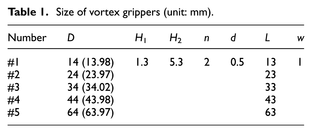
We processed five vortex grippers with different diameters of 14, 24, 34, 44, and 64 mm (named #1, #2, #3, #4, and #5, respectively). The first four grippers have a diameter change of 10 mm, and gripper #5 has a diameter change of 20 mm from gripper #4. The diameter of #5 is larger than that of #1 by 50 mm. Such a large change is sufficient to cover the influences on characteristics caused by the change in diameter. Except for the diameters, the five vortex grippers are identical in size, with two 0.5-mm-diameter nozzles and a 6.6-mm-high vortex chamber. Figure 2 and Table 1 present the detailed structural parameters. Figure 3 shows the actual processed vortex grippers.

Structural parameters of the vortex gripper.
Size of vortex grippers (unit: mm).
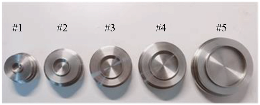
Vortex grippers used in the experiments.
Measurement of suction force
The most intuitive characteristic for the vortex gripper is the relationship between suction force and clearance: this is represented by an F–h curve. For obtaining the data of F and h, we built the measuring facility, as shown in Figure 4, wherein the left figure shows the structural diagram of the measuring facility and the right figure shows the actual facility. The vortex gripper is held in place by a locating mechanism and is parallel to the surface of the plate, which simulates the workpiece. The locating mechanism mainly consists of the following three parts: locating pins, a spring, and a spring stopper. The plate is fixed horizontally by an air guide, with its end on the force sensor, which is fixed on the sliding base, and the sliding track is driven by the feeding bold. Hence, the plate can also be moved up and down in the vertical direction. The laser meter located under the plate can continuously detect the position of the plate in the vertical direction and we then obtain the value of h. In the course of the experiment, the following steps were followed: (1) the feeding bolt was adjusted to bring the gripper into contact with the upper surface of the plate; (2) three locating pins were set and their ends were allowed to contact with the vortex gripper; (3) clamps were locked to hold the pins tightly; (4) spring was compressed and held in compression using the spring stopper; (5) laser meter was reset to zero; (6) given flow was supplied to the vortex gripper; (7) height of the clearance was continuously increased to obtain suction force F from the force sensor under different h conditions, and the measured data were recorded through data acquisition (DAQ).

Experimental facility for measuring suction force.
Measurement of pressure distribution
The pressure distribution of the vortex gripper reflects the flow field inside the vortex chamber. We measured the pressure distribution using the device shown in Figure 5. Figure 5(a) shows a diagram of the measuring facility, according to which the actual measuring facility, shown in Figure 5(b), was constructed. The measuring facility is mainly composed of three parts: a base, locating mechanism (mentioned in section “Measurement of suction force”), and measuring platform. The measuring platform can be divided into four parts: a sliding bar, a measuring table, a pressure sensor, and a displacement sensor. The procedure of the experiment was as follows: (1) the gasket was placed on the measuring table, and the vortex gripper was placed on the gasket. The thickness of the gasket is the height between the vortex gripper and the table surface. (2) The three locating pins were then stuck on the top of the vortex gripper. (3) The spring was compressed and then locked using the spring stopper. (4) Next, the gasket was removed carefully. (5) The given flow was supplied through the pressure-reducing valve. (6) The sliding bar and displacement sensor were then pulled using a linear motor, and finally, (7) DAQ and LabVIEW were used to complete the continuous acquisition of pressure.

Experimental facility of measuring pressure: (a) schematic representation and (b) actual measuring facility.
Theoretical analysis of maximum force with simplified model of vortex flow
Maximum force
The blue line in Figure 6 represents the typical relationship between suction force F and clearance h (F–h curve). When h is small (a-b segment of F–h curve), the positive pressure is formed in the thin gap because of the viscous effect when the air flows out of the gripper through the gap. And, the positive pressure raises the whole pressure distribution in the vortex chamber. Therefore, the vortex gripper generates a repulsive force (i.e. F < 0). As h increases in the b-c segment of F–h curve, the viscous effect and the resulting positive pressure get weak, and thus, the negative pressure distribution in the vortex chamber prevails such that the repulsive force gradually changes into the suction force. When h increases to a certain height, the F–h curve shows a turning point (point c in Figure 6). After the turning point (the c-d segment of F–h curve), the changing trends of F and h are contradictory, that is, h increases and F decreases because the air flows back into the vortex chamber to disturb the rotating flow. 10 This is why the next half of the F–h curve has a negative slope. The F–h curve is convex, and thus, the suction force has a maximum value (denoted as Fmax). Furthermore, the experimental and numerical simulation results by Li et al. reveal that Fmax occurs when the peripheral pressure of the vortex chamber is equal to or less than the atmospheric pressure.1,10

Typical F–h curve of vortex gripper.
As a suction device, the suction capacity is the most important indicator of the vortex gripper, and it depends on Fmax. The vortex gripper is able to pick up any workpiece of weight less than Fmax. The larger the value of Fmax, the heavier is the weight of the workpiece. Therefore, this study focused on the effect of the changing diameter of vortex chamber on Fmax and the internal flow field.
Simplified model of vortex flow at maximum force
The vortex gripper is injected with compressed air through the two tangential nozzles, causing the air in the vortex chamber to rotate at high speed. We assumed that the circumferential velocity is roughly proportional to the radial position, that is,
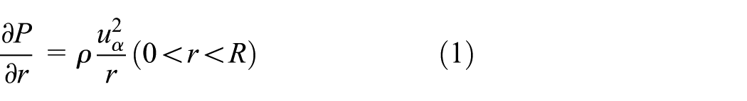
where P is the pressure, r is the radial position, and
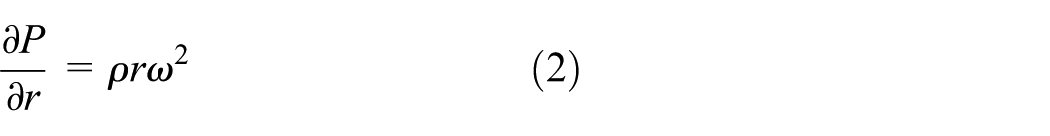
By integrating equation (2) in the radial direction, we obtain
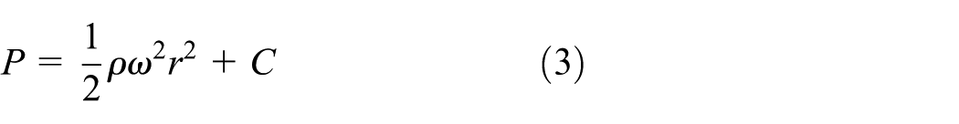
where C is a constant. As mentioned in section “Maximum force,” maximum suction force Fmax is approximately present when the peripheral pressure of the vortex chamber is equal to atmospheric pressure, that is, P = Pa when r = R. By considering this boundary condition, we can obtain a mathematical model of the pressure in the vortex chamber when the vortex gripper produces the maximum suction force

By integrating equation (4) with respect to the area, maximum suction force Fmax is obtained as follows

Equation (5) shows that Fmax is proportional to
The airflow is injected through the nozzles and swirls along the interior wall surface of the vortex chamber. The exit velocity of the nozzles determines the circumferential velocity of the periphery of the vortex chamber. In this study, the vortex grippers with different diameters have the same tangential nozzles. Therefore, we may further assume that the circumferential velocity at the outermost circumference of the vortex chamber (denoted as

According to equations (4) and (6), we can obtain the pressure distribution and maximum suction force of the five vortex grippers in the vortex chamber, as shown in Figures 7 and 8, respectively. The outermost circumferential velocity was set to
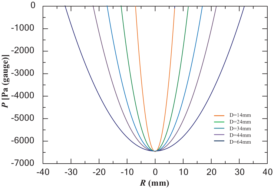
Theoretical pressure distributions.

Theoretical trend of maximum force.
The above-mentioned analysis and calculation results are based on two assumptions: (1) circumferential velocity
Results and discussion
F–h curves and maximum forces
Figure 9 shows the F–h cures of the five vortex grippers measured under the supply flow condition, Q=12 L/min. We determined that the increase in the diameter does not change the trend of the curve, but changes the position of the curve. As the diameter increases, the F–h curve moves up. The change in the diameter can significantly affect the suction force of the vortex gripper. We obtained the Fmax from the five curves and plotted the relationship curve of Fmax and diameter D of the vortex chamber in Figure 10. As the radius increases, Fmax increases significantly and then tends to be flat. From #1 (Fmax = 62.44 g) to #5 (Fmax = 94.56 g), Fmax increases by 51.4%. Compared with the theoretical result in Figure 8, the trend of the maximum suction force is accurately predicted through the theoretical model; however, the theoretical trend of Fmax greatly deviated from the experimental trend. This theoretical deviation might be a result of the two hypotheses. To clarify this, we used the measured pressure distribution to deeply analyze the effects of the diameter of the vortex chamber (section “Pressure distribution”).

F–h curves of the vortex grippers with different diameters.

F–D curve.
Pressure distribution
According to the F–h curves in Figure 9, all the vortex grippers achieve Fmax when h = 0.2 mm. Hence, we measured the pressure distributions of #1, #2, #3, and #4 under the supply conditions of Q = 12 L/min and h = 0.2 mm, as shown in Figure 11. The following observations can be made: (1) a negative pressure distribution is formed in the vortex chamber resembling a valley. (2) Both sides of the pressure distribution form a region in which the pressure changes relatively sharply, while the center has a pressure platform region that scarcely changes. (3) As the diameter increases, the area at which the negative pressure is formed increases expressively. However, the pressure platform at the center also expands and moves upward, largely offsetting the positive effect attained from the increasing the negative-pressure area.

Experimental and theoretical pressure distributions.
The calculation results of the simplified theoretical model are indicated by dashed lines in Figure 11. The theoretical curve cannot reproduce the pressure platform area in the vortex chamber. For smaller vortex grippers #1 and #2, the dashed curves fit well with the pressure-changing regions on both sides; however, for larger vortex grippers #3 and #4, the deviations between the theoretical and experimental curves are large. These large deviations are the reason why the simplified mathematical model cannot accurately predict the maximum suction force. This might result from the two assumptions about the circumferential velocity. Therefore, in the following section, we further explore the distribution of the circumferential velocity.
Circumferential velocity distribution
Directly measuring the velocity distribution in the vortex chamber is very difficult. Therefore, we indirectly estimated the circumferential velocity from the pressure distribution. Equation (1) in section “Simplified model of vortex flow at maximum force” gives the relationship between

Circumferential velocity distributions of (a) #1 (D = 14 mm), (b) #2 (D = 24 mm), (c) #3 (D = 34 mm), and (d) #4 (D = 44 mm) calculated from experimental pressure distributions
We calculated the peaks of the swirling speeds of the four circumferential velocities as 97.8, 90.5, 84, and 65 m/s for #1, #2, #3, and #4, respectively. The peak of the rotating speed decreases, while the diameter increases. We believe that this is because the compressed air from the tangential nozzles flows for a longer duration in the larger diameter of the vortex chamber, increasing the viscous resistance between the wall and flow. The change of the diameter is equal to the change of boundary condition, which causes the change of the flow field.21,22 Thus, the assumption that “
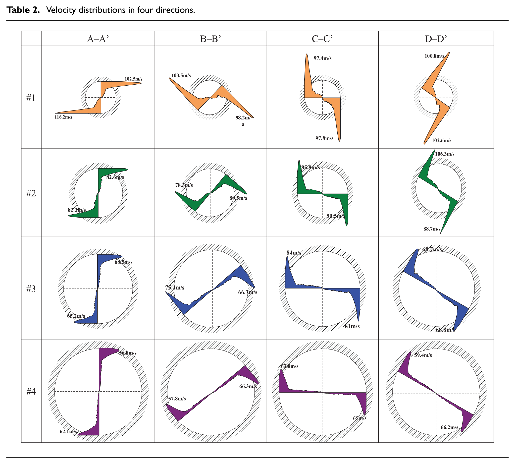
Furthermore, we measured the pressure distributions in multiple directions in the vortex chamber (see Figure 13) and calculated the circumferential velocity distributions. The results are listed in Table 2. In the circumferential direction, the shapes and values of the velocity distributions are almost the same. Therefore, as we assumed in the mathematical model, the change of the speed in the circumferential direction can be disregarded.

Measuring directions.
Velocity distributions in four directions.

From the above-mentioned discussion, we know that the continuous increase in the diameter is not conducive to the formation of a rotating flow and results in a decrease in the rotating speed. Thus, we can speculate that when the diameter increases to a certain extent, the free jet flow from the tangential nozzles will decay to zero along the wall of the vortex chamber. It cannot form a swirling flow in the vortex chamber and thus the vortex gripper cannot produce a suction force. This indicates that the trend of the Fmax–D curve will gradually decrease and eventually reach zero, as shown in Figure 14.

The predicted trend of Fmax–D curve.
Conclusion
The vortex gripper is a pneumatic non-contact suction device, which produces a negative pressure distribution and suction force through high-speed rotating airflow. Our research focused on the effect of the diameter of a vortex chamber on the maximum suction force and flow field. Based on the simplified theory and experiments, the following conclusions can be drawn:
The flow field structure in the vortex chamber is composed of two parts (1) a high-speed rotating airflow layer exists in the area close to the inner wall surface of the vortex chamber, in which the circumferential velocity reaches a peak and decreases sharply in the direction pointing to the center. (2) The airflow in the central portion is rotated by the layer of the high-speed rotating airflow, exhibiting an approximately linear distribution.
As the diameter of the vortex chamber increases, the distance along which the free jet flows increases. This significantly increases the viscous resistance between the wall surface and airflow. Therefore, an increase in the diameter causes a gradual decrease in the peak of the swirling speed.
In the circumferential direction, the shape and value of the velocity distribution are basically the same. Hence, the change of the circumferential velocity in the different directions can be disregarded.
As the diameter of the vortex chamber increases, the maximum suction force starts rising obviously and then tends to be gentle. Furthermore, the trend of the Fmax–D curve is estimated to gradually decrease and eventually reach zero.
The rotational flow field inside the vortex gripper is very complicated. The proposed simplified theoretical model and the three assumptions about the circumferential velocity distribution should be improved. In the future, we plan to use CFD and the flow field visualization method to study the characteristics and theoretical/empirical expressions of the rotating flow field of the vortex gripper, and propose a more reasonable and accurate mathematical model.
Footnotes
Appendix 1
Appendix 2
Appendix 3
Handling Editor: SA Shehzad
Declaration of conflicting interests
The author(s) declared no potential conflicts of interest with respect to the research, authorship, and/or publication of this article.
Funding
The author(s) disclosed receipt of the following financial support for the research, authorship, and/or publication of this article: This work was supported by the National Natural Science Foundation of China (No. U1613203), the Shenzhen Science and Technology Plan (No. JCYJ20170816172938761), and the Fundamental Research Funds for the Central Universities (No. 51221004).