
Abstract
Based on previous research results obtained in the authors’ laboratory, in this article, we develop, refine, and summarize the disk-transverse, blade-bending, and shaft-torsion coupled-vibration phenomena of a multi-disk rotor with blades with multiple cracks. Three methods are used to explore these phenomena, namely, the finite element method, experimental method, and assumed mode method. The assumed mode method is primary, and the others play subsidiary roles. Some beneficial and interesting results are presented in this article. First, the authors used the assumed mode method and finite element method (ANSYS) to explore and compare the change rules of the natural frequencies and mode shapes in a rotor. Second, it is pointed out how multi-cracks affect the coupled-vibration phenomena of a single-/multi-disk(s) system. Numerical calculation results also show that the crack depth, number of crack blades, as well as the symmetry of the crack blades, affect the natural frequencies. Finally, the experimental results are discussed and the advantages and limitations of using each of the three methods are given. While the experimental measurement method advanced herein may have some limitations, the results should guide future research.
Introduction
Cracks often occur in components of rotating machinery, such as rotating shafts and blades, due to defects in manufacturing and installation or due to long-term external forces and periodic temperature loads. Such cracks cause local flexibility and change the dynamic characteristics of the structure. Therefore, academics and practitioners have spared no effort in pursuing online crack detection in rotating machinery. The failure-free use of air turbines and propellers is very important in flight safety, so their reliability requirements have become more stringent. Many aircraft accidents have been associated with engine failure in recent years. Cracks and fractures are the most serious effects in such failures. Therefore, to the method of estimating the dynamic characteristics of a rotor to avoid accidents is a very significant issue, and it has also become an academic and industrial research hotspot.
Here, we briefly introduce some of the relevant research on cracked rotor systems published. Vikrant et al. 1 adopted the concept of the dynamics compliance operator along with the theory of modal analysis. They developed a model of a cracked structure using MATLAB/Simulink. The methodology was administered to reveal the complex dynamics of a cracked bar. These results could be extended to handling multi-dimensional problems. Khaji and Mehrjoo 2 utilized finite element and genetic algorithms to develop a crack detection technique that detected crack location and depth in beam-like (BL) systems. Kim et al. 3 used a new method for detecting cracks in wind turbine blades. This method was able to detect cracking in a notched specimen. Rezaee and Fekrmandi 4 adopted perturbation analysis to experimentally explore the free non-linear vibration influence of a cantilever beam with a crack. Lu and Chu 5 utilized finite element method (FEM) to experimentally compare the vibrational response of a shaft. They found that the acoustic emission signal is a convenient and effective way to locate a crack in a shaft, and the vibration signal can be practicably used to determine the shaft crack’s depth. Peng et al. 6 adopted the harmonic balance method (HBM) and FEM to investigate the influence of cracks on the transmission matrices in a rotor. They found that there are differences between the transmission matrices for the super-harmonic and the fundamental frequency components. Moreover, the main differences are determined by the crack location. Kit and Sushko 7 offered the solutions of steady heat conduction and thermo-elastic axisymmetric problems of a thin plate disk. They confirmed the displacement vector and the stress–tensor components of cracks in a case study. Lu et al. 8 studied the non-linear response characteristics of a high-pressure rotor in a hollow shaft in a double transverse rotor system with a breathing transverse crack using a finite element (FE) model. Rehman et al. 9 employed numerical and experimental methods to investigate mistuned and tuned repeating structures and derived good correlations between the crack location/depth and damage indices. Ma et al. 10 adopted a FE model to explore the influence of tooth cracks and the profile shift and time-varying mesh stiffness of vibrational responses in a profile-shifted gear rotor system. Ozer and Sofuoglu 11 used the FEM and linear elastic fracture mechanics to investigate a magnetic disk with a horizontal subsurface crack. Dong and Chen 12 analyzed the bending vibration of a shaft in a rotor with open cracks without rotation using a FE model. They investigated the depth of crack changes on the mode shapes and the effects of the slenderness ratio of frequencies in the rotor. Rzadkowski13,14 explored the model of blade and bladed disk, early. In recent years, Rzadkowski and Maurin 15 and Rzadkowski et al. 16 used a FEM model to explore low pressure (LP) steam-turbine and aircraft-engine last-stage bladed-disk mistuning. Geometrical and material approaches were applied and numerically compared mistuning effects. Natural frequencies (NFs) and mode shape change were explored at the same time. It is noteworthy that the above studies were only focused on subsystems with a crack or mistuning in the rotor system.
The relevant research in the author’s laboratory stemmed from the research of Wu and Huang, 17 who employed the assumed mode method (AMM) to study the coupled vibration of a cracked blade in a single-disk rotating shaft–disk–blade system. Their rotor system comprised a single rigid disk, and the crack was of the set-open type. Dimarogonas–Paipetis 18 theory was used in the investigation. Wu and Huang explored how the depth and location of only one cracked blade affected the coupled vibration of the rotor system. Chiu and Huang 19 also adopted the AMM to explore a flexible disk rotor and defined some rules, namely that a rotor exhibits three types of coupled vibrations: inter-blade (BB), disk-blade (DB), and shaft–disk–blade (SDB) modes. Chiu and Huang 20 explored how a crack affects these three types of coupled-vibrations type tuning a shaft–flexible disk–blade system. Recently, Zhou et al. 21 and Chiu et al. 22 used the FEM to investigate a single-/multi-flexible disk rotor with springs and compared their results with earlier research results.
In addition, some researchers have made use of experimental methods to study rotor system coupled-vibration characteristics. For example, Ma et al. 23 utilized the FE and experimental methods to explore a 2-degree-of-freedom (DOF) model with one- or four-blade rubbings. Yin et al. 24 applied experimental and FE methods to explore the dynamic behavior of a rotating cantilever Timoshenko beam under static load and centrifugal force. Venkatachalam and Prabu 25 utilized the FE and experimental methods to analyze the vibration phenomenon of a shaft–disk rotor system. Lu et al. 26 explored several non-linear problems in a flexible rotor system. Cui et al.27,28 studied the problems related to the rotor system. Chiu et al. 29 used the experimental method, FEM, and AMM to investigate coupled-vibration phenomena in a multi-flexible disk rotor. Some beneficial and interesting results were presented, including the fact that the experimental method could not distinguish flexible disk frequencies of the system completely and in detail.
This article improves the methodology of investigating the blade-bending, shaft-torsion, and disk-transverse coupled-vibration phenomena in a multi-disk rotor with multi-cracked blades. In this article, the disks are considered to be flexible and the blades are modeled as Euler beams with staggered angle and the cracks are of open type. The FEM uses ANSYS to analyze the rotor, and the rotor change rules of NFs and mode shapes are explored. We also supply a qualitative and quantitative overview of a multi-disk rotor with multi-cracked blades. The experimental method was also adopted in this article. Finally, we develop, refine, and summarize results for a multi-disk rotor with cracked blades using the experimental method, AMM, and FEM, based on early research results from the authors’ laboratory.
Theoretical analysis
The multi-disk rotor with multi-cracks blades is displayed in Figure 1. The rotor includes three subsystems, for example, blades, flexible disk, and shaft. The blades have stagger angle and crack. The flexible blades fixed onto the outer edge of the disk with a stagger angle β. According to industrial equipment such as turbine and fans and the authors previous research, 30 we choice 60° in this article.

(a) The multi-disk rotor with multi-cracks and (b) the stagger angle.
The torsion energies equations of shaft–disk subsystem were 20

where the torsional displacement in a rotating coordinate system used
Figure 2 displays a disk, free outside and clamped inside, rotating at a Ω constant speed; the inner and outer radii of disk used

The rotating disk’s coordinates and geometry.
The transverse vibration energies equations of disk were 20


where the disk-transverse displacement used


Figure 3 displays as a rotating cantilevered blade with a stagger angle

Blade’s deformation and coordinate builds.
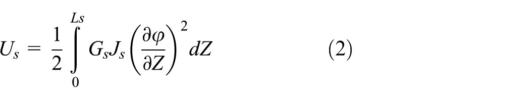
The kinetic and strain energies equations of blade were 20


where
According to Dimarogonas and Paipetis, 18 they adopted Castigliano’s rules and constituted a 5 × 5 matrix of local flexibility for a rectangular beam containing a transverse crack. The other terms are neglected, and supplied the bending moment was the main term. The crack’s released energy is given as follows

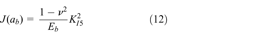
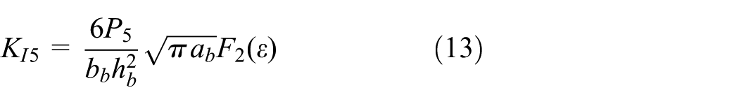

where
The moment of bending with the crack could express

and the crack’s released energy Uc is

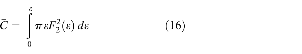
where
The total blade’s displacements


The continuous system discretize is utilized by AMM

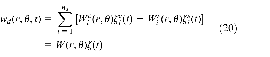

where


where

is a beam function for blade with


The above equation is transformed into an energy expression; the following results are obtained using the Lagrange equation and the discretized equations of motion in matrix notation as
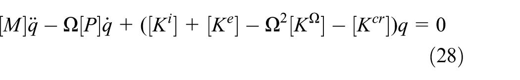
where

Free vibration analysis in an ordinary way, it is assumed the solution is of the form
FEM
In Zhou and colleagues,21,22,29 the authors used three kinds of FEM software to simulate a rotor system. Based on the results in those references, the authors found ANSYS software to be most accurate and observed that errors using ANSYS were less than 1%. As mentioned above, only the FEM adopted ANSYS to calculate parameters of the SDB system studied in this article. Table 1, whose parameters are adopted in the AMM and FEM, gives the relevant geometric and material properties. The effect of angle variation was studied in Yang and Huang. 30 Figure 4 is a FE mesh model. The subsystem’s element types in the rotor system were simulated many times, which engendered different frequency results, and only the most outstanding ones were selected. The perfect element types, namely the blades, disks, and shaft, are chosen as three-dimensional (3D) hexahedral solid elements. After being tested many times, the number of elements and nodes areas follows. The single-disk system utilized 70,000 nodes and 60,000 elements and the two-disk system utilized 110,000 nodes and 100,000 elements. The shaft torsion vibration’s boundary condition is clamped-free. The fracture mechanics module in ANSYS is chosen as open-crack type in this article. It is important to note that the singular element can be generated with a 0.1 mm crack(s) using ANSYS, as shown in Figure 4(b).
Geometric and material parameters.


FE mesh of a multi-disk rotor system with cracks: (a) system and (b) crack.
Experimental device
Experimental target
Figure 5 shows the experimental framework. The framework is a two-disk and six-blade rotor with a cracked blade. Figure 5(b) shows the cracked blade, which is located at

(a) Schematic layout of experimental, (b) cracked blade, (c) arrangement, and (d) data-acquisition instrument.
Experimental instrument
Integrated circuit piezoelectric (ICP) triaxial accelerometers were selected. The acceleration sensors of output locations are located at P2 and P3 on the disk and H1 marks the hammer location that is hammered in the shaft (see Figure 5(c)). Figure 5(d) shows the data-acquisition instrument.
Experimental procedure
The multi-disk rotor and a bearing seat paste acceleration sensor are connected to the linked appliances, analog-to-digital conversion card, and amplifier. The data are collected by AcqKnowledge software, which captures the multi-disk rotor vibrational response. The frequency analysis uses one-point response and the multi-point acquisition method.
Sensors
We used ICP triaxial accelerometers from PCB Piezotronics/MTS Systems Corp. Triaxial accelerometers (Model 35A16, Serial No. 105873) offer simultaneous measurements in three orthogonal directions, permitting the entire vibration experienced by a structure to be analyzed. Each unit incorporates three separate sensing elements that are oriented at right angles with respect to each other. Each direction (axis) is considered an individual channel by the data system. Multi-pin electrical connectors, individual cable leads, or multiple coaxial connectors provide the signal outputs for the x-, y-, and z-axis acceleration. The sensitivities of the triaxial accelerometers are as follows: (a) x-axis, 101.3 mV/g and 10.33 mV/m/s2; (b) y-axis, 99.1 mV/g and 10.11 mV/m/s2; (c) z-axis, 102.4 mV/g and 10.44 mV/m/s2.
Key points
The blades use flushbonading blades. The disk–shaft and blades–disk joints are welded to ensure fixation. Capturing the vibration of the rotor system response must also include removing filtering and interference. We utilized filtering and digital signal processing technology to remove both.
Numerical results
Table 2 tabulates the NFs of the subsystem for coupling vibrations. The frequencies are used as the numerical results for verification and interpretation.
Tabulation of NF (Hz) of subsystem.

NF: natural frequency.
Tables 2–6 and Figures 6–22 were drawn without rotation
Six modes of NFs (Hz) of a single-flexible disk, five-blade system with cracked blades determined by two methods.
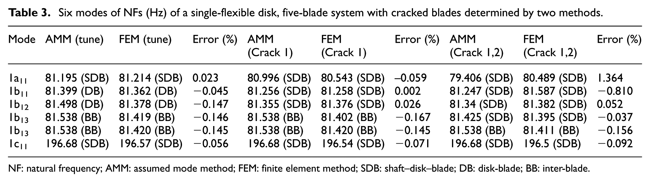
NF: natural frequency; AMM: assumed mode method; FEM: finite element method; SDB: shaft–disk–blade; DB: disk-blade; BB: inter-blade.
Seven modes of NFs (Hz) of a single-flexible disk, six-blade system with cracked blades determined by two methods.

NF: natural frequency; AMM: assumed mode method; FEM: finite element method; SDB: shaft–disk–blade; DB: disk-blade; BB: inter-blade.
Seven modes of NFs (Hz) of a single-flexible disk, six-blade symmetric system with cracked blades determined by AMM.

NF: natural frequency; AMM: assumed mode method; SDB: shaft–disk–blade; DB: disk-blade; BB: inter-blade.
Eleven modes of NFs (Hz) of a two-flexible disk, six-blade system with one cracked blade determined by AMM.

NF: natural frequency; AMM: assumed mode method; SDB: shaft–disk–blade; DB: disk-blade; BB: inter-blade.

Frequency variation due to asymmetric cracked blade in a five-/six-blade, single-disk system.

Five modes of a single-disk, five-blade system determined by AMM.

Six modes of a single-disk, five-blade system determined by FEM.
Six modes of a single-disk, five-blade system with one cracked blade determined by AMM.
Six modes of a single-disk, five-blade system with one cracked blade determined by FEM.

Six modes of a single-disk, five-blade system with two cracked blades determined by AMM.

Six modes of a single-disk, five-blade system with two cracked blades determined by FEM.

Seven modes of a single-disk, six-blade system determined by AMM.

Seven modes of single-disk, six-blade system with one cracked blade determined by AMM.

Seven modes of single-disk, six-blade system with two cracked blades (1,2) determined by AMM.

Frequency variation due to symmetric cracked blade in single-disk, six-blade system.

Seven modes of single-disk, six-blade system with two cracked blades (1,4) determined by AMM.

Seven modes of single-disk, six-blade system with three cracked blades (1,3,5) determined by AMM.
Night modes of two-disk, five-blade system with three cracked blades (*) determined by AMM.
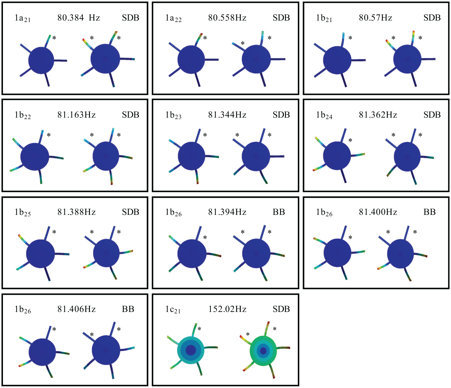
Eleven modes of a two-disk, five-blade system with three cracked blades (*) determined by AMM.

1a11-mode frequency variations with crack–depth ratio for a six-blade system with a rotor with two cracked blades (1,2) determined by AMM: (a) scale 40–90 Hz and (b) scale 80.0–81.4 Hz.

Frequency response functions for two output locations.
There are two cases proposed in this article: the first concerns how the crack affects the coupling vibration in a single-disk system, and the second concerns frequency variation due to a symmetric crack blade in a six-blade, single-disk system. In the first case, Figure 6 shows the frequency variations for a five- or six-blade rotor. Tables 3 and 4 present the six and seven modes, respectively, of the NFs of a flexible disk and a five-/six-blade system with cracked blades obtained using two methods. These cracked blades are located at an asymmetric place in the rotor system. Modes 1a and 1b are groups in which the blade’s first mode leads in a five-blade system. Note that the mode-change phenomenon displayed in Figure 6 is not drawn in a linear scale. Furthermore, two reference marks are shown, ω = 81.538 and 207.43, which respectively express that the system frequencies predominate by a cantilevered first bending of the blade and a first torsion of the shaft (Table 2). For a single-flexible disk rotor system in Dimarogonas and Paipetis,
18
the coupling modes could be grouped into three coupling-mode types: SDB, DB, and blade-blade (BB).
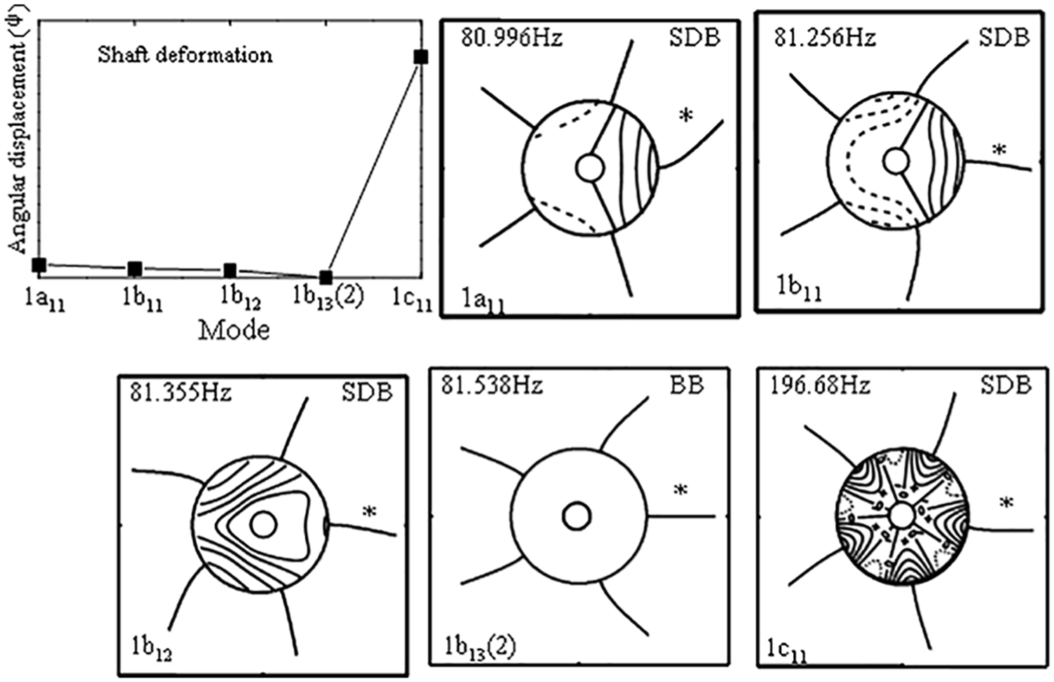
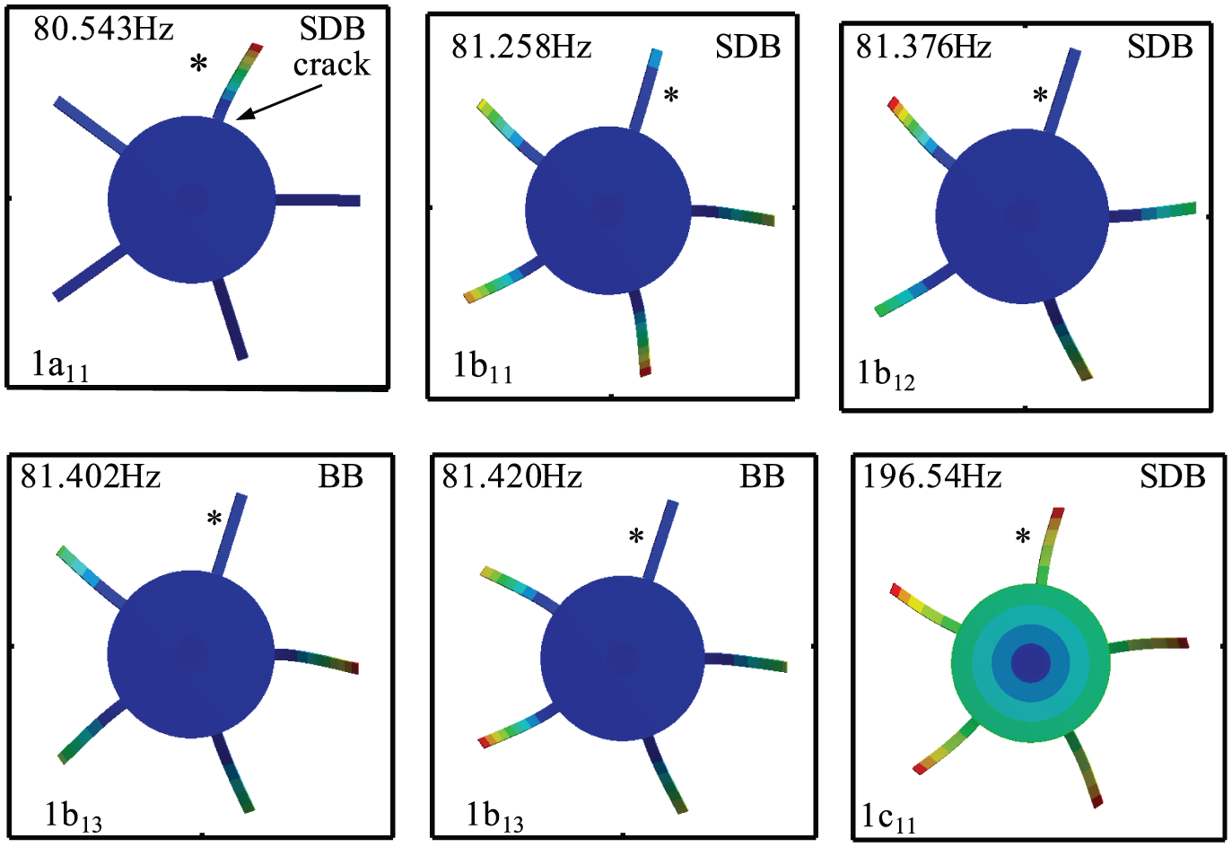
Figures 7–12 illustrate the mode shapes of a single-flexible disk, five-blade system with cracked blades determined by the AMM and ANSYS. The x-y figures display the torsion displacement of the shaft. The deflections of the blade and disk are illustrated in the diagrams. The mode type and NFs are shown at the top of each plot. Figures 8, 10, and 12 are the modes determined by ANSYS; the others are those determined using the AMM. After comparing the results between these figures and Tables 3 and 4, interesting phenomena were revealed. The key point is that all of the results match when using both the AMM and ANSYS.
According to Chiu and Huang,19,20 we understand why both methods are somewhat different. The following explanations apply. First, we knew the number of frequencies that the blade’s first mode leads to, Nb, and that the shaft’s first mode leads to the 1c11 mode, namely 1 (one). Second, when using the AMM, we assumed that the rotor is of bending blade clamped-free type, the torsional shaft is fixed-free, and the transverse disk is clamped-free. From the numerical results, we found that the deformation of the disk is much smaller than that of the blade and the shaft; that is,
Figures 13–15 show the mode shapes of a single-flexible disk and six blades with cracks determined by the AMM. The mode-change rules are similar to those in Figures 7–12. The main purpose of these figures is to only illustrate the disk deformation; therefore, we do not show the coupled-vibration change phenomena in these figures.
The second case study is of frequency variation due to a symmetrically cracked blade in a single-disk, six-blade system, and the results are shown in Figure 16 and Table 5. When a crack appears in a symmetrical blade, the coupled-vibration phenomenon is interesting and different. First, the modes are predominated by cantilevered first bending of blades in the following order: SDB (1a11), DB (1b11), SDB (1b12), DB (1b13), and repeat BB (1b14) modes in cracked blades located in the number 1 and 4 blades of the rotor system. If the cracked blades are located in numbers 1, 3, and 5, the modes, in ascending order, are SDB, DB, SDB, DB, and repeat BB (1b14) modes that are bifurcated SDB and BB modes. If the cracks are located in blade numbers 1, 2, 4, and 5, the mode sequence is SDB, DB, SDB, DB, SDB, and DB, and the BB mode disappears. Finally, the 1c11 (SDB) modes of the shaft predominate and are not affected by the cracked blades.
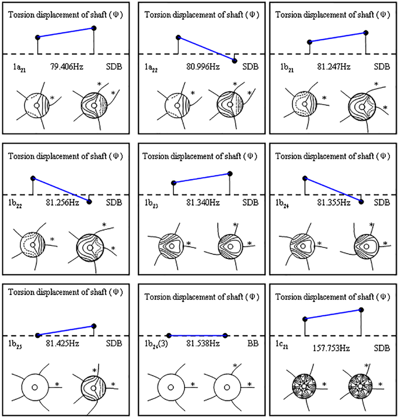
Figures 19 and 20 show the mode shapes of a two-flexible disk, five-blade system with three cracked blades case determined by AMM and FEM. The first disk has one crack located in the number 1 blade, and the second disk has two cracks, one each in the number 1 and 2 blades. The upper x-y figure shows the shaft’s torsion displacement. The deflections of blades and disks are illustrated inside the diagrams as follows. The mode types and NFs are drawn on each plot’s middle line. Comparing the cases depicted in Figures 19 and 20 to Figures 6–20 and Tables 3–5, it can be seen that the system will retain its mode shapes and frequencies in a single-disk system and combine with each other. In other words, they are linear relations. The second phenomenon indicates that it is difficult to distinguish which is a single- or two-blade cracked disk from the mode.
Figure 21 shows the frequency variations with crack depth of the 1a11 modes, which consequently evolve into SDB modes, for a six-blade rotor system with two cracked blades (1,2) determined by the AMM. This case study has three lines, the first cracked blades are located at depth ratios of 0 (as in Chiu and Huang),
20
0.4, and 0.6. The second cracked blade’s depth ratio ranges from 0 to 0.92. The location of the cracked blade is
Figure 22 shows the frequency–response functions. To easily identify the experimental results, we only use P2 and P3 output responses. As mentioned above, we use a crack–depth ratio of 0.85, which is easy to identify. We used an absolute value for the amplitude ratio and removed the interference and filtering in this figure. As a result, five peaks can be seen. From Chiu et al. 29 and from comparison with Table 6, the frequencies of the third peak (near 81 Hz) are the blades’ first mode guides. The second peaks (near 70 Hz) are the cracked-blade mode guides (1a21, 72.56 Hz). From Chiu et al., 29 the first peak is the support frame. From the experimental results, two interesting phenomena can be observed. First, the results of the experiment conform to those determined by the AMM and FEM. Second, the method utilized cannot completely display flexible disk frequencies of the system and in the detail found in Chiu et al., 29 for example, 1a (except 1a21) and 1b modes.
Finally, we describe the variation of the rotor’s natural frequencies with rotation. The numerical results for this case are normalized with respect to the first-order natural frequency (
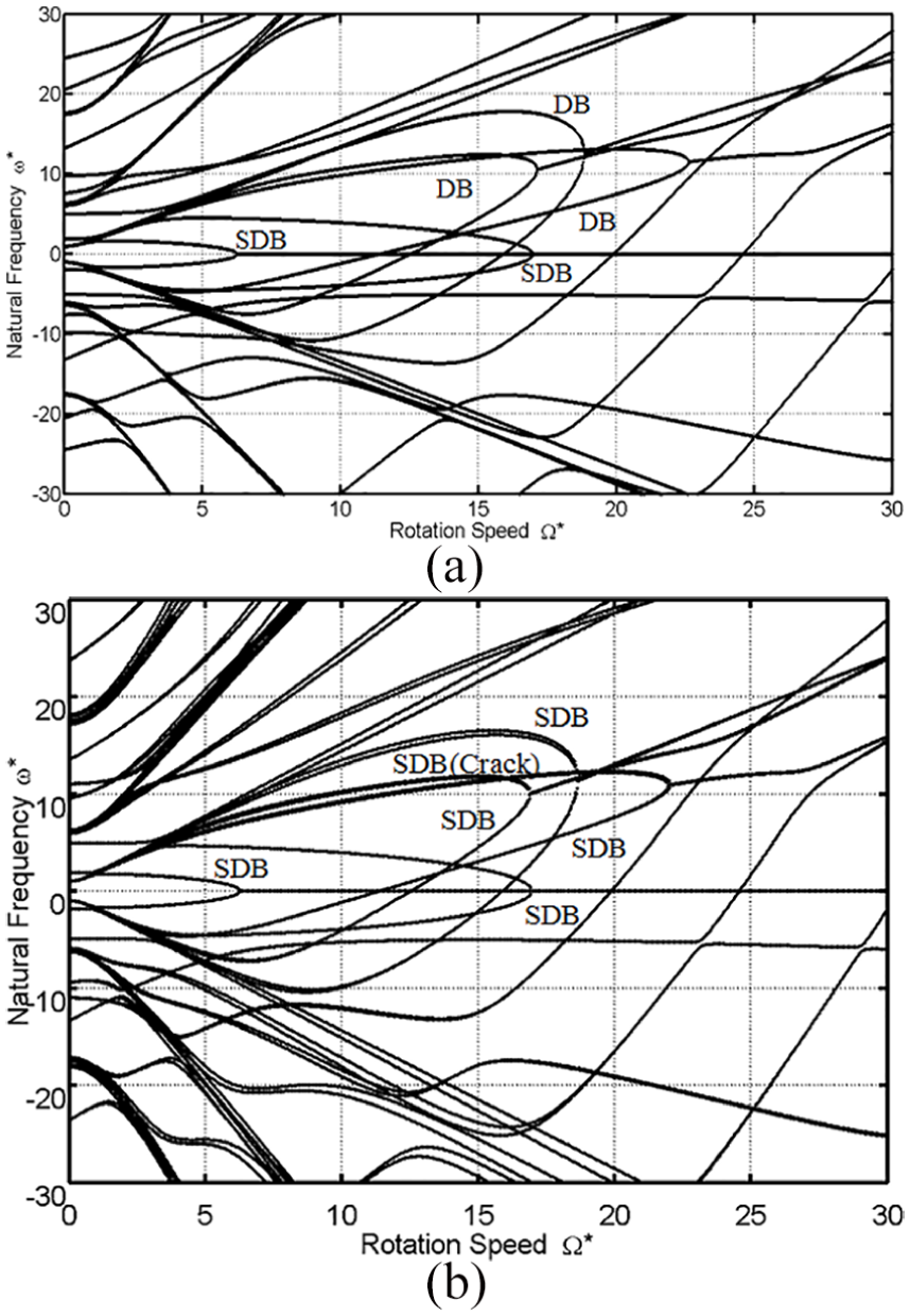
Variation of eigenvalues with rotation speed for two-disk, five-blade rotor: (a) tuned system and (b) three-cracked-blade system.
Conclusion
In this article, we developed, refined, and summarized the disk-transverse, shaft-torsion, and blade-bending coupled-vibration phenomena of a multi-disk rotor with multi-cracked blades according to early research results from experiments conducted in the authors’ laboratory. Three methods were combined: the AMM, FEM, and experimental methods. The AMM is primary, while the other two methods played subsidiary roles. The research was initiated by studying the mode change resulting from a single-flexible disk, five-/six-blade rotor. The coupling modes were displayed as three group types: DB, BB, and SDB.
When the rotor has multi-cracked blades, the change rules were given. First, the experimental results and FEM results conformed to the results of the AMM. Second, it was found that the FEM is not advisable to use in analyzing the complicated change phenomena of coupled vibration in a multi-disk rotor with multi-cracked blades. FEM cannot distinguish different situations from the disks between a tuned system and a cracked-blade system, because the deformation is less than the set error and is ignored by the FEM. Numerical calculation results also showed that the crack depth, number of cracked blades, as well as the symmetry of the cracked blades, affected the natural frequencies. The two most interesting things revealed by the study are that symmetry of the cracked blades will cause the balance of frequency and modes to be misjudged. In addition, two different depth ratios of cracked blades are more affected by deep cracks in a blade. Finally, it was found that the experimental method could not display the complete and detailed flexible disk frequencies of the system. The experimental method, however, is just an auxiliary method, and the measurement method has several limitations. The authors hope that this research can serve as a guide for similar research.
Footnotes
Appendix 1
Acknowledgements
Thanks Dr Li join the China National Fund application in 2018.
Handling Editor: Sang-Wook Kang
Declaration of conflicting interests
The author(s) declared no potential conflicts of interest with respect to the research, authorship, and/or publication of this article.
Funding
The author(s) disclosed receipt of the following financial support for the research, authorship, and/or publication of this article: This entire study works are sustained by Fujian Nature Foundation (no. 2016J01039), Xiamen City Foundation (no. 3502Z20173037), and Scientific Research Climbing Project of Xiamen University of Technology (no. XPDKT18016).