
Abstract
Each guided elastic wave mode is composed of propagating and non-propagating branches. Non-propagating branches associated with complex wavenumbers are substantially different from the propagating ones. Accurate calculation of the transcendental dispersion equation for complex wavenumbers and arbitrary ranges of frequencies is usually very difficult, especially for demanding cases such as those involving composite materials and curved structures. In this article, an extended Legendre orthogonal polynomial method is presented to determine non-propagating waves in a functionally graded piezoelectric cylindrical shell. The extended Legendre orthogonal polynomial method can obtain complete solutions without the tedious iterative search. Results are compared with those published earlier to validate the extended Legendre orthogonal polynomial method, and the convergence of this method is also discussed. Dispersion characteristics of the non-propagating waves in various graded piezoelectric cylindrical shells are studied and three-dimensional dispersion curves are plotted. The effects of piezoelectricity, graded fields, and the mechanical and electrical boundary conditions on dispersion curves are illustrated. The displacement amplitude, stress, and electric potential distributions are also analyzed in detail. Numerical results show that the extended Legendre orthogonal polynomial method is very efficient to retrieve the guided waves of any nature and the modes of all orders.
Keywords
Introduction
Functionally graded piezoelectric material (FGPM) is a new type of piezoelectric material in which the electro-elastic properties are considered to vary in a desired direction(s). FGPMs have been widely used in microelectromechanical systems, aerospace, and smart material structures due to their advantages compared to traditional laminated piezoelectric materials.1,2 The mechanical stresses can be significantly reduced or eliminated in FGPM structures, and the advantages of the FGPMs can improve the reliability and lifespan of piezoelectric devices. Demands from the non-destructive evaluation and ultrasonic technology fields make the study of wave propagation in FGPM structures a topic of practical importance.
Many computational models and methods have been developed to investigate wave propagation in various functionally graded material (FGM) waveguides in the past few decades. The layered models are the most frequently used ones, which divide an FGM structure into a number of homogeneous or inhomogeneous layers, while a certain assumption of material parameters in each layer has been adopted for analysis by virtue of various layer element methods, such as finite layer element, 3 linearly and quadratic inhomogeneous layer elements,4,5 spectral element, 6 and transfer matrix method. 7 There are also many methods taking FGM as a continuous gradient medium to be proposed for analyzing guided waves in FGM structures, such as the Wentzel–Kramers–Brillouin method, 8 power series method, 9 reverberation-ray matrix method, 10 state vector method, 11 and orthogonal polynomial series method.12,13 Such methods have been successfully applied to computing, two-dimensional (2D), and less often three-dimensional (3D), dispersion curves for guided waves. Recently, the guided waves in nanostructures and functionally graded nanostructures have also been extensively investigated.14–20 Most of the research is concentrated on propagating waves (i.e. real wavenumber), but focus on non-propagating waves (i.e. complex wavenumber) is quite limited. From a mathematical point of view, non-propagating waves have purely imaginary or complex wavenumbers. Indeed, dispersion equation relating wavenumber to frequency, a transcendental equation, is difficult to find the complex roots, especially for demanding cases such as those involving composite materials and curved structures.
The non-propagating wave modes associated with imaginary or complex wavenumbers are different from the real wavenumber modes. The non-propagating wave modes are attenuated with increasing propagation distance, so they are usually referred to as non-propagating or evanescent waves. Note that evanescent wave modes are also present in perfectly elastic materials without any energy leakage. They represent local modes that exist at discontinuities. 21 Such modes would play an important role in the detection of the shape and size of defects with the development of guided wave detection technology. Thus, the study on the evanescent waves receives more and more attention. The purely imaginary roots of the dispersion equation for an elastic plate were obtained by Lyon 22 as early as 1955. Mindlin and colleagues23,24 established the existence of modes at the cutoff frequencies, the amplitude of which varies linearly with the propagation distance, and also demonstrated the presence of complex roots of the Rayleigh–Lamb equation. The physical properties and energy transportation of the evanescent waves in elastic media were discussed detail in the second volume of Auld. 25 Using a numerical spectral method, Pagneux and Maurel 26 determined the complex Lamb wave spectrum. Diligent et al. 27 predicted and measured the non-propagating Lamb modes at the free end of a plate and pointed out the value of the knowledge of non-propagating modes for the detection of corrosion defects. Damljanović and Weaver 28 developed a theoretical framework to study the propagating and evanescent waves in cylindrical waveguides. Simonetti and Lowe 29 investigated the nature of the evanescent modes and emphasized the existence of complex branches in the dispersion curves of an elastic plate. Recently, Quintanilla et al. 30 calculated the full spectrum for guided wave problems in the plate and layered cylinder using a spectral collocation method. Yan and Yuan 31 investigated the conversion of evanescent Lamb waves into propagating waves via a narrow aperture edge and discussed the potential application of evanescent waves in structural health monitoring. Most of the existing research on the evanescent waves focuses on the isotropic material and simple structure such as a flat plate. However, cases where high values of attenuation are present and complex materials such as FGM are considered have been rarely investigated due to the great difficulties encountered when computing their dispersion equations. The study of FGM structures is a tough task because the material properties depend on the thickness coordinate and some specific assumptions concerning their variations are needed.
There are some traditional methods to solve the transcendental dispersion equation in the complex domain, such as Newton iteration method and Muller’s method. 32 However, these methods have their own limitations in dealing with the multivariate transcendental equations. The Newton iteration method needs the first-order derivative of the determinant that is usually difficult to obtain. Muller’s method is time consuming and not concise in dealing with multivariate equations. 33
In this article, we present an extended Legendre orthogonal polynomial method (ELOPM) to determine the complete spectrum for guided waves in an FGPM cylindrical shell which, to the best of the authors’ knowledge, has not been studied before. In a previous study, the Legendre polynomial method has been used for studying the real wavenumber modes but not for the complex wavenumber modes. The ELOPM can reduce the wave propagation problem to an eigenvalue matrix equation and can obtain all the real, imaginary, and complex solutions but without an iterative process. Two known cases are provided for validation purposes. The 3D full dispersion curves for various FGPM cylindrical shells are obtained. The effects of piezoelectricity, graded fields, and mechanical and electrical boundary conditions on the dispersion characteristics of non-propagating guided waves are illustrated. The displacement amplitude, stress, and electric potential distributions are also discussed to analyze the specificities of the non-propagating guided waves.
Mathematics and formulation of the problem
Consider an orthotropic FGPM cylindrical shell with graded material properties in the radial direction, as shown in Figure 1. In a cylindrical coordinate system Orθz, let a, b, and h be the inner and outer radii and the thickness, respectively, and the radius–thickness ratio η = b/h. The material properties, including density ρ(r), elastic coefficient C(r), piezoelectric coefficient e(r), and dielectric coefficient
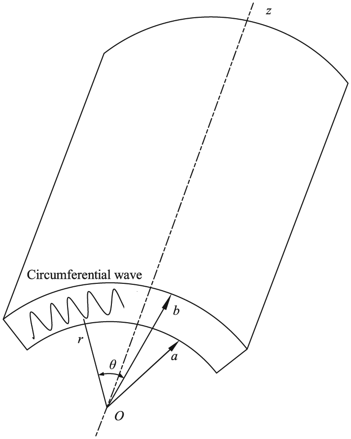
Geometry of the problem.
The system of governing equations involves the motion equations, the electrical displacement equilibrium equations, and the constitutive equations 34


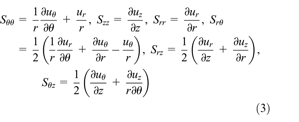
where σij, Sij, Di, and Ei are the stress, strain, electrical displacement, and electrical intensity components, respectively. ui denotes the mechanical displacement component in the ith (i = θ, z, r) direction.
The general strain–displacement relations in the cylindrical coordinate system are given by
The electric field intensities Ei (i = r, θ, z) are the functions of the electric potential φ and in the cylindrical coordinate system are given by17,35

where φ is the electric potential.
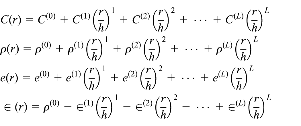
Since the material parameters are the functions of r, they can be fitted into the following form
According to the Einstein summation convention, the above formula can be written as

where l is the order number and C(l), ρ(l), e(l), and
The traction-free and electricity open-circuit boundary conditions require that

where X(r) is a rectangular window function defined by
For a free harmonic wave in the circumferential direction of a cylindrical waveguide, we assume the mechanical displacement and the electric potential components to be of the form

where Ui and Y represent the amplitude of vibration in the ith direction and the amplitude of electric potential, respectively; k is the wavenumber; ω is the angular frequency; and i is the imaginary number.
An ordinary way of reducing the number of resolving equations is to substitute equations (3)–(7) into equation (2) with the following substitution into equation (1). As a result, the governing differential equations in terms of displacement components and electric potential can be obtained. Here, the case of a radially polarized FGPM cylindrical shell is given
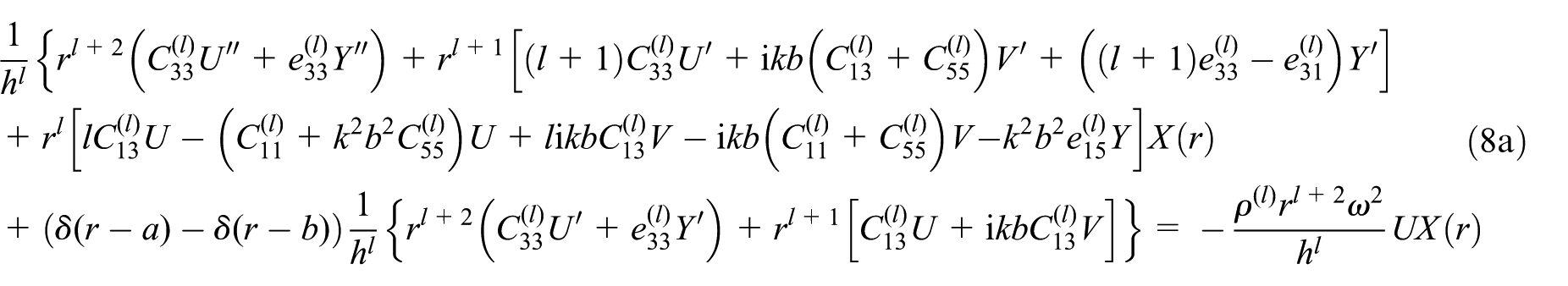

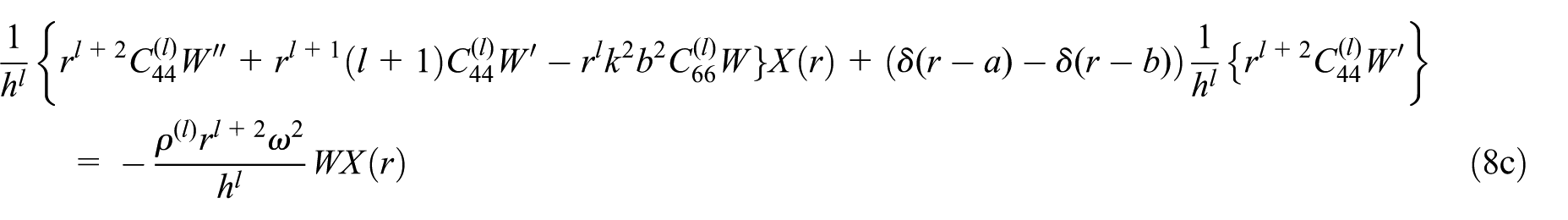

where a prime denotes the derivative with respect to r. U, V, and W represent the amplitude of vibration in the r, θ, and z directions, respectively. Obviously, equations (8a), (8b), and (8d) are coupled with each other and are associated to the circumferential Lamb-like wave. Equation (8c) is independent and it represents a shear horizontal (SH) wave, which is relatively easy to be solved analytically. So here we just give the solving process of a circumferential Lamb-like wave.
To solve equations (8a), (8b), and (8d), the field quantities are expanded into Legendre polynomial basis
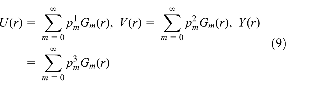
where

where Pm is the Legendre polynomial of order m.
Substituting the mechanical displacements and the electrical field into equations (8a), (8b), and (8d), then multiplying both sides of each equation by the complex conjugate

where
Note that in equation (11), once we specify a fixed value of ω, it does not have the structure of a general eigenvalue problem in k. In previous research works,12,13 equation (11) was transformed into an eigenvalue problem with eigenvalue ω. For a propagating wave, it is simple to specify real k and then solve for ω. But for an evanescent wave, it is useless because the wavenumber is complex, which involves a multivariable search. To deal with this problem, we develop a new solution procedure to recast the equation again in the form of a general eigenvalue problem, as shown below. For mathematical convenience, we introduce two new matrices

And substituting equation (12) into equation (11) yields

Multiplying both sides of equation (13) by an inverse matrix

Combining equations (14) and (10) yields

where
If we define a new matrix

then equation (15) can be written as

Up to this stage, the problem is reduced to an eigenvalue problem with complex eigenvalues k(ω). The solution of equation (17) can give the generally complex wavenumber and the field profiles. Compared to equation (11), the necessary vector introduction enables k as the eigenvalue. Here, we use the Mathematica function “Eigenvalues” for the problem of the type Ax = λx.
Numerical results
The equivalent theoretical analysis model is used to calculate the effective material property of the FGPM cylindrical shell composed of two different materials. As described in Han et al.’s 37 paper, it can be expressed as

where Fi and Vi(r), respectively, represent the material property and volume fraction of the ith material.
And

Similar to equation (5), V2(r) can be expressed as a power series expansion. In this article, the FGPM cylindrical curved shell is composed of PZT-4 (inner surface, r = a) and Ba2NaNb5O15 (outer surface, r = b). The material parameters are listed in Table 1.
38
Two different graded fields are considered:
Parameters of the two piezoelectric materials.
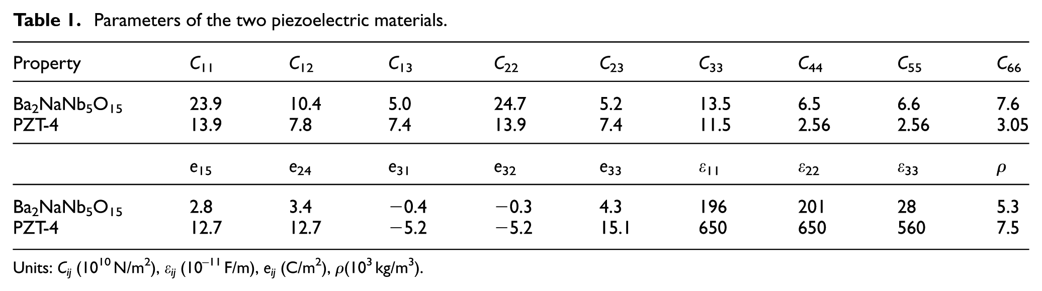
Units: Cij (1010 N/m2), εij (10−11 F/m), eij (C/m2), ρ(103 kg/m3).
Approach validation and convergence of the problem
Based on the foregoing formulations, a computer program has been developed to calculate the dispersion behavior for FGPM cylindrical shells. As there were no investigations on the non-propagating wave in FGM structures before, to the best of our knowledge, we verify the validity of the obtained results with the existing results for the propagating wave in an FGM plate and for the non-propagating wave in a homogeneous steel plate. We calculate a cylindrical shell with a large radius–thickness ratio (η = 100, h = 1 mm), which can be approximately regarded as a flat plate. It is initially tested for a Lamb wave in an FGM linear plate composed of chrome (Cr) and ceramic materials, and the material properties have been provided in the literature. 39 Figure 2 shows the resulting phase velocity dispersion curves of Lamb wave, where the black dotted lines represent the literature results from the Peano series method and the red solid lines represent our results. The polynomial results match very well with the literature ones obtained by the Peano series method.

Phase velocity dispersion curves of a Lamb wave for an FGM plate; red lines represent our results and black dotted ones represent the literature results using the Peano series method.
Note that the above example only studied propagating wave without considering non-propagating wave, which can only give the dispersion curves of Lamb wave in real wavenumber range. Then we calculate the full spectrum of Lamb wave, including the real and purely imaginary and complex wavenumbers, in a homogeneous steel plate and make a comparison of the literature results. The material parameters are ρ=7932 kg/m3, C11=281.757 GPa, C12=113.161 GPa, and C44=84.298 GPa. The non-dimensional frequency and non-dimensional wavenumber are adopted,

Dispersion curves of a Lamb wave in a steel plate; dotted lines represent results from our method and solid lines represent the literature results from the spectral collocation method; real branch is shown in blue, purely imaginary branch in black, and complex branch in red.
Next we discuss the convergence of the ELOPM. Figure 4 presents the dispersion curves of an SH wave in a linear FGPM cylindrical shell (η = 10, a = 9 mm) with electrical open circuit, when the truncation order M takes the values 8, 9, and 10, respectively. We can observe that more and more modes converge as M increases, and the first five real modes and the first four imaginary modes are convergent when M = 8 and 9, and the first six real modes and the first five imaginary modes when M = 10. We can think that at least the first (M – 1)/2 modes are convergent.
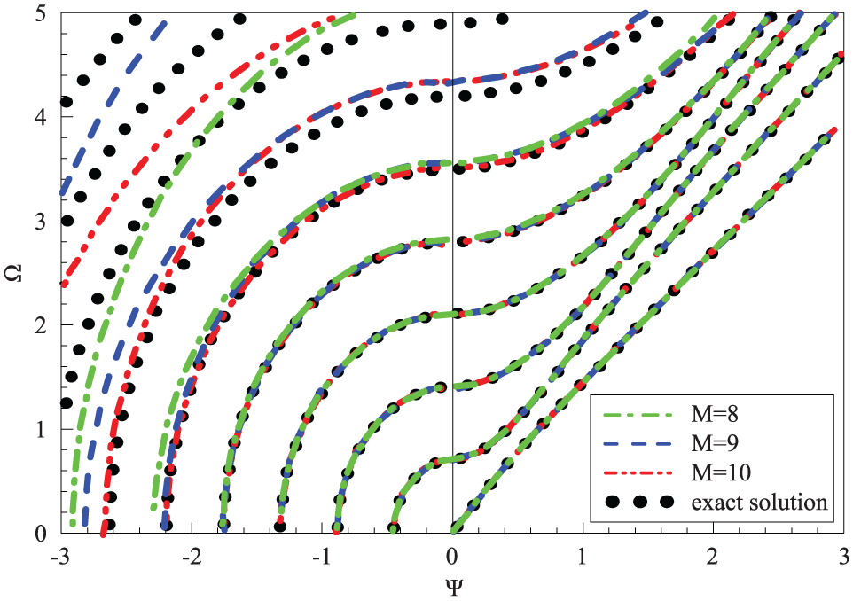
Dispersion curves of an SH wave in a linear FGPM cylindrical shell for various “M” values.
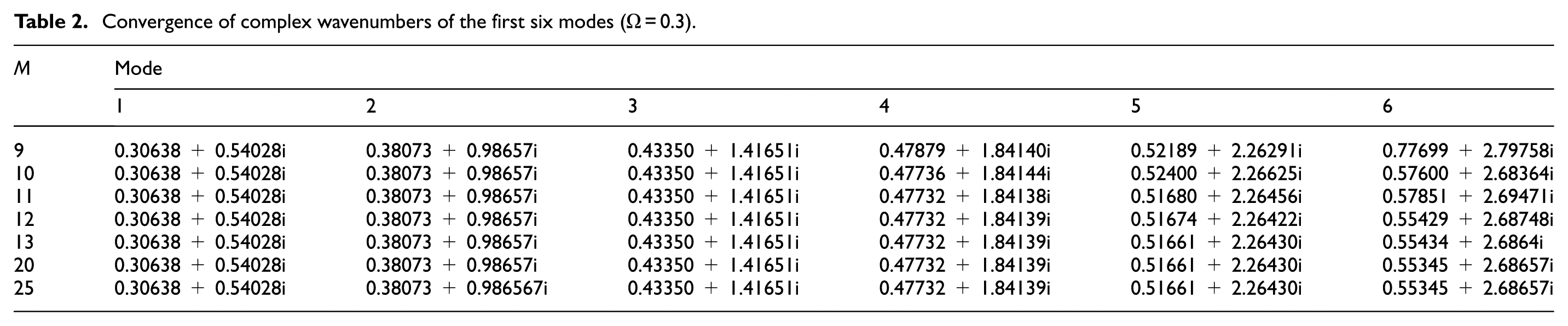
For Lamb-like waves, we present the dispersion curves of real wavenumber modes in a linear FGPM cylindrical shell with various “M” values, as shown in Figure 5. Moreover, we tabulate the complex Lamb-like wave solutions in Table 2 since graph is not convenient for comparison. The first six complex wavenumber solutions are given when Ω = 0.3. These numerical results also show that the solutions are convergent as M increases, and the real solution is easier to converge than the complex one. From these results, good convergence of the proposed method can be observed. A larger M is required to obtain solutions of the higher modes, which will cause more computer memory and long time. Generally, our interest lies in the low modes, so we take M = 30 in this article.
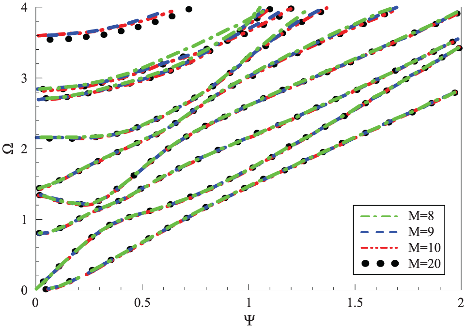
Dispersion curves of Lamb-like real wavenumber modes for various “M” values.
Convergence of complex wavenumbers of the first six modes (Ω = 0.3).
3D dispersion curves for an FGPM cylindrical shell
In general, a clearer visualization of the solutions and a better understanding of the topology of the dispersion curves require a 3D representation of the dispersion loci in the space as first suggested by Mindlin and Medick. 23 Consequently, we plot the complete 3D dispersion curves in the frequency–complex wavenumber space. Since circumferential Lamb-like and SH waves are independent of each other for the orthotropic case, their dispersion curves are described individually, with different colors for clarity when necessary.
The resulting 3D frequency spectra of the FGPM cylindrical shell (η = 10, a = 9 mm) are shown in Figure 6, in which dark blue dotted lines are purely real solutions, the green ones are purely imaginary solutions, and the red ones are complex solutions.
3D full dispersion curves: (a) circumferential SH wave and (b) circumferential Lamb-like wave.
It can be seen from these figures that the purely real and purely imaginary solutions appear in pairs of opposite signs. For the complex branches, if a complex wavenumber is a solution, then its complex conjugate is also a solution, and two others are also solutions by multiplying the aforementioned ones by −1. Purely real k values correspond to propagating modes, the displacement of which is a sinusoidal function for both space and time. The purely imaginary ones correspond to non-propagating modes, the displacement of which exhibits an exponential decay in the propagation direction and the decaying rate depends on the wavenumbers. The complex ones are other different non-propagating modes, the displacement of which exhibits a damped sinusoidal decay.
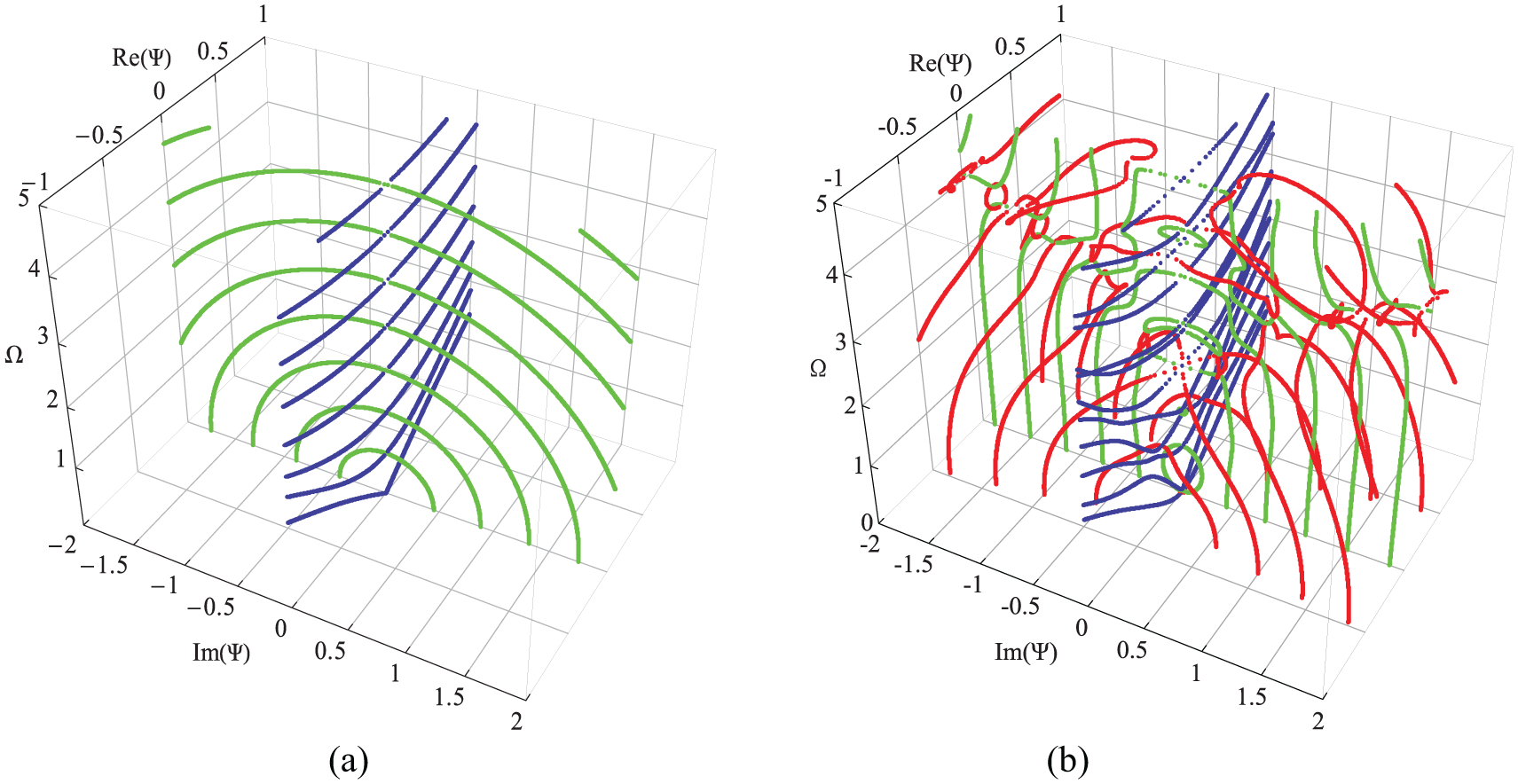
For simplicity and clarity, only the curves in one quadrant are represented, as shown in Figure 7. As observed in Figure 7, for circumferential SH waves, there are purely real and purely imaginary branches. Purely imaginary branches always start at zero frequency and end at some cut-off frequencies with increasing frequency. For circumferential Lamb-like waves, there are purely real, purely imaginary, and complex branches. We can notice that, for purely imaginary branches, those with large imaginary values start at zero frequency and end at cut-off frequencies. But those with small imaginary values are very different, and they start at a certain frequency and end at the adjacent cut-off frequency forming a half loop. For complex branches, some of them start at zero frequency and collapse onto the minima of purely real or imaginary branches, at a low frequency. It is interesting to note that some complex loop appears with increasing frequency, which connects two adjacent imaginary branches in the 3D space, from the minimum of one to the maximum of another. Figure 8 shows the corresponding 2D dispersion curves, and the peculiar complex branches are marked with an elliptical symbol. These curves reveal that local extrema can trap the complex branches (if close enough) or deflect the complex branches. In addition, the magnitude of the real part of the complex branches is usually much smaller.

3D dispersion curves in one quadrant: (a) circumferential SH wave and (b) circumferential Lamb-like wave.

Two-dimensional dispersion curves of a circumferential Lamb-like wave.
Effects of piezoelectricity and graded field on dispersion curves
In order to investigate the effects of piezoelectricity on the dispersion curves of the FGPM cylindrical shell, we here assume that the piezoelectric and dielectric coefficients are zero, and other material parameters remain unchanged. Since circumferential SH wave is independent of electric field, we only consider circumferential Lamb-like wave. The first quadrant of the resulting 3D dispersion curves of the circumferential Lamb-like waves in the FGM cylindrical shell, with all the cutoffs and branches, is shown in Figure 9, with the same color scheme as in Figure 10.

3D dispersion curves of a circumferential Lamb-like wave in an FGM cylindrical shell.

Dispersion curves of a sinusoidal FGPM cylindrical shell: (a) circumferential SH wave and (b) circumferential Lamb-like wave.
Through careful comparison with Figure 7(b), we can notice that piezoelectricity has a significant effect both on the complex branches and on the real branches. For purely imaginary branches, a few of them start at the cut-off frequency and continuously extend with increasing frequency, which is different from the case of the FGPM cylindrical shell. In addition, those branches that start at zero frequency and end at cut-off frequencies disappear. The complex branches are also very different, and those complex loops disappear.
Then we turn our attention to the effects of graded field. Figure 10 shows the dispersion curves of the FGPM cylindrical shell with the graded field sin(0.5π(r – a)/h). The results indicate that the graded field also has a significant effect on the dispersion characteristics. By careful comparison with Figure 7(a) and (b), we can notice that the cut-off frequencies become larger. As a result, for purely imaginary branches of circumferential Lamb-like waves, the loop becomes larger. For any real wavenumber mode, the frequency at a given real wavenumber is much larger than that in the previous linear graded cylindrical shell, namely, the guided wave propagates more quickly. The reason lies in that the material volume distributions are different for the FGPM cylindrical shells with different gradient fields, and the wave velocity is related to the material properties. For complex branches of circumferential Lamb-like waves, the effects are more significant with increasing frequency and mode order. Interestingly, another local inflection point appears on the sixth real branches (marked with a circle) as the frequency continues to increase. As suggested by Onoe et al.’s 40 research, the complex branch is sensitive to Poisson’s ratio and the geometry of the cross section. Poisson’s ratio is an important parameter reflecting the material properties. The complex branches would have different behavior or some modes might not even exist for waveguides with different material properties.
Effects of boundary condition on dispersion curves
In this section, we discuss the effects of boundary condition on dispersion curves. In a previous study, the boundary condition is mechanical free and electricity open circuit. For mechanical fixed and closed-circuit boundary conditions, the displacement and electric potential should satisfy
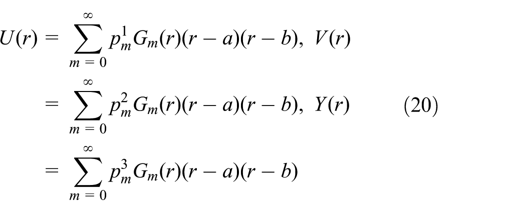
Taking the mechanical fixed and electricity closed-circuit boundary conditions as an example, the boundary conditions are satisfied by expanding the amplitude of the displacement and electric potential as
Simlarly, substituting equations (2)–(5) and (20) into equation (1), the governing differential equations in terms of displacement components and electric potential can be obtained. The other derivation process is the same as before. Figures 11 and 12 present the obtained 2D dispersion curves of the FGPM cylindrical shells with mechanical fixed and electricity closed-circuit boundary conditions and with the mechanical free and electricity closed-circuit boundary conditions, respectively. By comparison with Figure 8, we can find that the effects of mechanical and electricity boundary conditions on dispersion curves are significant, including both on the real branches and on the complex branches, especially for the low-order modes, as marked with a rectangular box in Figures 11 and 12. It can be seen from Figure 12 that the electricity boundary condition has a more significant effect on the complex branches than that on the real branches, and the complex loops connecting two adjacent imaginary branches disappear. The numerical results also show the specificity of our method, which can automatically incorporate the mechanical and electrical boundary conditions into the motion equation.

Two-dimensional dispersion curves of a circumferential Lamb-like wave for an FGPM cylindrical shell with mechanical fixed boundary and electricity closed-circuit boundary conditions.

Two-dimensional dispersion curves of a circumferential Lamb-like wave for an FGPM cylindrical shell mechanical free and electricity closed-circuit boundary conditions.
Amplitude distributions of displacement and electric potential
In this section, we discuss the amplitude distributions of displacement and electric potential fields for the FGPM cylindrical shell. The displacement and electric potential fields produced by a Lamb mode, propagating in the circumferential direction, can be obtained according to equations (7) and (9). Combining equation (9) with equation (7) gives
We consider a special position (marked with a circle in Figures 7(b) and 8) where the first complex branch approaches near the minima of the real branch, at about Ω = 1.2. Figures 13 and 14 present the displacement and electric potential distributions in the radial and wave propagation directions when Ω = 1.21019, complex wavenumber ψ = 0.22580–0.02696i, and Ω = 1.21815, real wavenumber ψ = 0.19727, respectively. These figures reveal that a complex branch exhibits a damped sinusoidal distribution and can propagate a very long distance due to the small imaginary wavenumber. Moreover, the displacements ur are very similar at the two frequencies. So we can conclude that the complex branch will transit to a real branch with increasing frequency. In fact, a non-propagating mode should be considered as a mode branch instead of being a mode itself, which forms a mode in conjunction with the real branch.

Amplitude distributions of displacement and electric potential when Ω = 1.21019 and ψ = 0.22580–0.02696i.
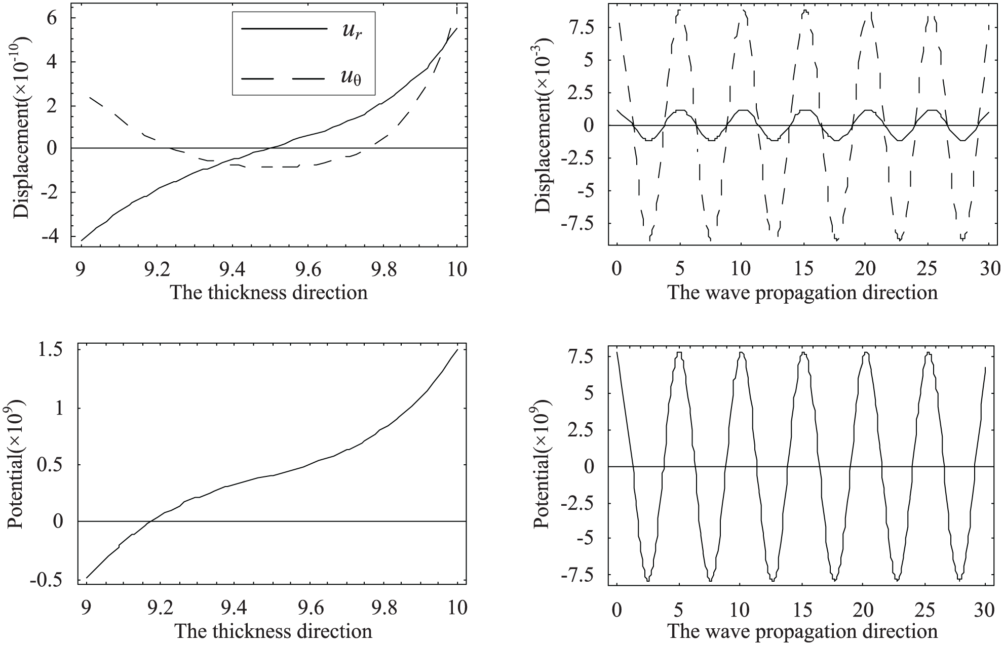
Amplitude distributions of displacement and electric potential when Ω = 1.21815 and ψ = 0.19727.
Figure 15 presents the stress and electric displacement distributions in the thickness direction for the complex branch at Ω = 1.21019 and complex wavenumber ψ = 0.22580–0.02696i. We can notice that the stress Trr and Trθ and the electric displacement Dr at the inner and outer surfaces are zero. The calculation results further demonstrate the correctness of the method to deal with the boundary conditions.
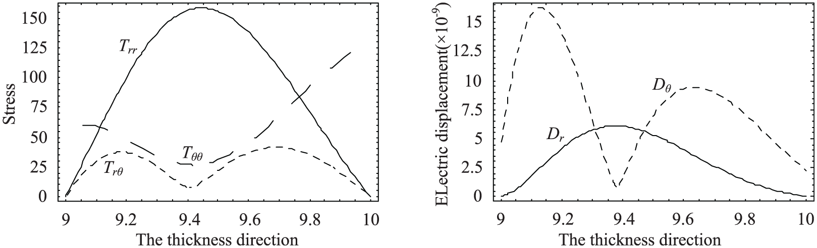
Stress and electric displacement when Ω = 1.21019 and ψ = 0.22580–0.02696i.
Conclusion
We present an ELOPM to determine the full dispersion spectrum of the guided waves in FGPM cylindrical shells. The method throws new light on the guided wave problems involving composite materials or curved structures which are usually very demanding for the traditional methods. The proposed method can transform the set of differential equations for the acoustic waves into an eigenvalue problem, which can yield the complete solution straightforwardly and avoid the tedious iterative search of the conventional methods. For the first time, the complete 3D dispersion curves of the FGPM cylindrical shell are illustrated. Numerical results show that there are only purely real and purely imaginary branches for circumferential SH waves, but for circumferential Lamb-like waves there are purely real, purely imaginary, and complex branches. Interestingly, most complex branches collapse onto the minima of purely imaginary branches and local inflection points occasionally appear on higher order real branches. The location of local extrema is sensitive to material properties. Complex branches exhibit both local vibration and local propagation. With increasing frequency, a complex branch will turn into a real branch. All of the piezoelectricity, graded fields, and mechanical and electrical boundary conditions have significant effects on dispersion curves. The deep understanding of the complete spectrum is crucial for a correct model of practical wave propagation. We believe that the proposed method could be of interest in non-destructive evaluation and also to deal with other waveguides with more complex materials and structures, such as magnetoelectroelastic materials and multilayered structures.
Footnotes
Appendix 1
The explicit expressions for the element are
where
Handling Editor: Mohammad Arefi
Declaration of conflicting interests
The author(s) declared no potential conflicts of interest with respect to the research, authorship, and/or publication of this article.
Funding
The author(s) disclosed receipt of the following financial support for the research, authorship, and/or publication of this article: The authors gratefully acknowledge the support by the National Natural Science Foundation of China (No. U1504106), the Fundamental Research Funds of Henan Province (No. NSFRF140301), the Program for Innovative Research Team of Henan Polytechnic University (T2017-3), and the Key Scientific and Technological Project of Henan Province (No. 192102210189).