
Abstract
This article presents an approach for the compliance analysis and lightweight design of a two-degree-of-freedom rotating head by considering both gravity and joint/link compliances, which provides a comprehensive understanding on the posture adjustment mechanism of five-degree-of-freedom hybrid manipulator. A kinetostatic analysis is carried out to consider both externally applied wrench imposed upon the end-effector and gravity of all movable components. Then, a deflection analysis integrating both joint and link compliances and formulation of component compliance matrices are completed by using a semi-analytical approach. Finally, the lightweight design of two-degree-of-freedom rotating head is realized by considering the deflection constraints. This approach enables to effectively evaluate the deflections of end-effector caused by both payload and gravity under given operation conditions. Moreover, the established method provides reliable guidelines for the design of two-degree-of-freedom rotating head with superior static rigidities and dynamic behaviors.
Introduction
In modern industries, for example, aerospace, shipbuilding, and precision instruments, five-axis computer numerical control (CNC) machine tools play a critical role in manufacturing machinery components with superior quality.1–3 Two-degree-of-freedom (2-DOF) rotating head is an essential part to fabricate these five-axis CNC machine tools because of its excellent performance, such as compact structure, flexible motion, high accuracy, and high rigidity. In conjunction with 1T2R (T denotes a translation DOF and R a rotational DOF) three-degree-of-freedom (3-DOF) parallel mechanism, 2-DOF rotating head is also used to construct five-degree-of-freedom (5-DOF) hybrid robots, Tricept robot, 4 Exechon robot, 5 and TriVariant robot, 6 for example. Due to their large workspace, high accuracy, and rigidity, they are preferable to developing plug and play module, and building customized manufacturing units or systems. With the aid of these robots, it is convenient to achieve automatic drilling and riveting for large components of an aircraft, field processing for fuselage and wing surface, interference assembling for cylinder pin holes in automobile engines, and wire-electrode cutting for large steel structures. Thus, they have been widely used to machine, weld, and assemble large structures in the fields of aerospace, automotive, and construction. 7 It should be pointed out that 2-DOF rotating head is necessary to realize the postural adjustments in five-axis CNC machine tools and 5-DOF hybrid robots when they are used in the applications mentioned above.
As a key functional component of five-axis CNC machine tools, 2-DOF rotating head, for example, biaxial rotary milling head, 8 has gained massive research interests. Extensive efforts have been made to explore the design methods of mechanical structure and transmission, the manufacturing and assembly techniques of the mechanism, and the performances, including stiffness, accuracy, dynamic characteristics, and reliability.8–18 Gao et al.14–16 overcame the difficulties of large volume, low rigidity, and low carrying capacity in higher pair transmission by investigating four types of biaxial rotary milling heads, for example, six-rod whole hinge double-row drive type, six-rod whole hinge singe-row drive type, single screw drive type, and double screw drive type. Cai et al.17,18 established a technique system for heavy loading biaxial rotary milling head by integrating the analysis of kinematics, statics, dynamics, heat property, and thermomechanical coupling. They also carried out a systematic study on modal test, thermal analysis, and precision experiments to confirm the validity of the developed system. Hence, their works lay a theoretical and experimental foundation for optimizing the heavy loading biaxial rotary milling head. In addition, some 2-DOF parallel mechanisms are designed to a 2-DOF rotating head as special device, for example, solar tracker. 19
As the main body of 5-DOF hybrid robot, a great deal of attention has been paid to 3-DOF parallel mechanism of the hybrid robot.20–30 However, as the postural adjustment mechanism of 5-DOF hybrid robot, 2-DOF rotating head is rarely studied. Yet, some works 31 have demonstrated that the gravity of 2-DOF rotating head has an important influence on the positioning accuracy of hybrid robots, especially when they have horizontal layout, leading to an issue in need of considerable further investigation for achieving a lightweight yet rigid design of the 2-DOF rotating head. In addition, dynamic characteristics of 2-DOF rotating head should be incorporated into the analysis when it is attached to the five-axis machine tools involving high frequencies of acceleration–deceleration cycles. To improve the dynamic characteristics of the mechanism and performance of machine tools, lightweight design has been proposed as it enables the mechanism to either keep the stiffness unchanged while reducing its weight or keep the weight unchanged while improving the stiffness. 32 Such lightweight design can be achieved by optimizing the topology, material, and structural parameter of the mechanism, and is widely applied to the optimal design of machine tool structure components.33–37 For example, Zulaika et al. 36 proposed a lightweight design method to minimize the mass of structural components of a milling machine by considering the maximum of the material removal rate. These results demonstrate that the lightweight design can avoid elastic dynamics modeling but implicitly improve the dynamic performance. Unfortunately, it has rarely been used in optimizing the structural parameters of 2-DOF rotating head.
This article presents an approach for the compliance analysis and lightweight design of a 2-DOF rotating head that can be used as the posture adjustment mechanism of 5-DOF hybrid manipulators. Having addressed the significance of lightweight design, the article is organized as follows. First, the system description and frame establishment are briefly introduced. Then, the procedures that realize the compliance analysis and lightweight design are developed systematically. Finally, a numerical example is given by using the established method to confirm its validity. It is expected that the approach presented in this article could provide a reliable guideline for the lightweight design of 2-DOF rotating head.
System description and frames establishment
An A/C rotating head generally consisted of an A-axis, a C-axis, and an end-effector. As illustrated in Figure 1, an electric spindle serves as the end-effector, and it rotates with respect to the A-axis which further rotates with respective to C-axis, forming a 2-DOF rotating head.

Body fixed frames of the 2-DOF rotating head.
The coordinate systems of the body fixed frames of electric spindle {RE}, A-axis {RA}, and C-axis {RC} are shown in Figure 1. Assuming that α is the rotating angle between A-axis and C-Axis, and β is the rotating angle between electric spindle and A-axis, the orientation matrices of {RE} and {RA} with respect to {RC} can be expressed as


where
Compliance analysis
To integrate the component compliances and the gravity-induced deflections into analysis, a semi-analytic compliance model of the 2-DOF rotating head is presented in this section.
Force analysis
To establish a linear map between the externally applied wrench imposed on the end-effector and the joint reaction forces, the static analysis of the rotating head is essential. To solve the joint reaction forces of A-axis, it requires investigating the forces acting on the electric spindle as shown in Figure 2. Integrating these forces and moments with respect to point E, the static equilibrium equations can be derived as follows

where

where

Free body diagram of the electric spindle.
The joint reaction forces of C-axis can be obtained in a similar approach as illustrated in Figure 3. Considering the forces and moments acting on point E, the static equilibrium equations can be derived as follows

where mA is the mass and
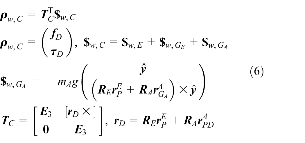
where

Free body diagram of the electric spindle and A-axis.
Deflection analysis
To develop the linear map between the deflection twist of end-effector and the joint deflections of the A-axis and C-axis, the deflection analysis of the rotating head is carried out in this section. With the aid of angular velocity superposition theorem and small deformation synthesis principle, the following relationship can be obtained

where δa and δr are linear deflection at point

where

where
Compliance modeling
With the aforementioned linear maps to hand, the deflection model of the rotating head can be formulated. By assuming a linear elasticity of component and using Hooke’s law, the following equation can be obtained

where


The elements in

It can be found that the established model contains two components, that is, the deflection caused by the resultant externally applied wrench and that caused by the gravity-induced deflections


where


where
Lightweight design
As discussed above, the lightweight design of the 2-DOF rotating head is of great importance to improve the performance of a posture adjusting mechanism of 5-DOF hybrid robot. To achieve such an aim, the motor and reducer of C-axis are connected directly to reduce the axial size of its supporting component as shown in Figure 4. Then, a motor-synchronous belt-reducer is employed as the drive system of A-axis to reduce the width of rotating head. In addition, the exterior geometry of the rotating head’s outer cover is designed to be approximately convex, which can avoid interference with the synchronous belt and reduce both the weight and supporting width of such rotating head. Furthermore, aluminum alloy is used to manufacture the supporting components of the A-axis and C-axis whose strength is reinforced by using some strengthening ribs in their inner space.

Structure diagram of the rotating head.
To meet both excellent static rigidities and dynamic behaviors of the system, this article presents an approach to implement the lightweight design by considering the deflection constraints of the end-effector. For convenience, let
where


where
Since the rigidities of supporting structures and shafts are much higher than those of supporting bearings and reducers, the overall rigidity of rotating head is dominated by the rigidities of bearings and reducers. Therefore, the optimal design of rotating head requires selecting appropriate supporting bearings and reducers. It can be implemented by exploring the performance of different combination of bearings, reducers, and corresponding structure. The solution with lightest weight will be the final design. In this process, it is necessary to ensure the maximal deflection caused by the elasticity of rotating head to meet the predefined constraints. For simplicity, a set of feasible designs of the A-axis and C-axis are predetermined, and their mass and compliance coefficients are evaluated in advance. It is worth pointing out that the maximal specifications of bearings and reducers might not meet the deflection constraints under the given scope of structure size. Whenever this occurs, it requires relaxing constraints of deflection or increasing structure size.
Numerical example
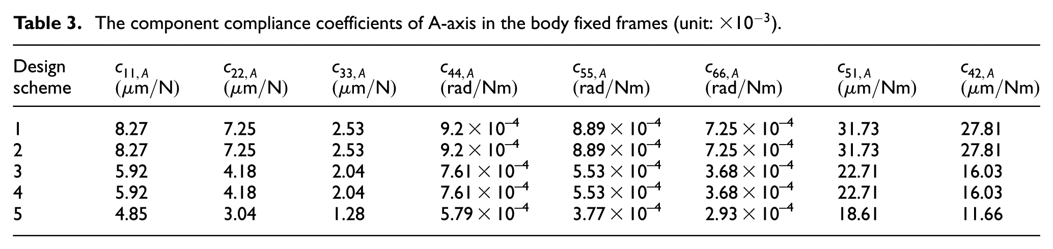
A lightweight design of the 2-DOF rotating head shown in Figure 1 is taken as an example to verify the effectiveness of the proposed method. Table 1 lists the selected five schemes of the lightweight design for the rotating head and the corresponding specifications of standard products. Tables 2–4 give the dimensions, component compliance coefficients, masses, and mass center of the selected components. The data are obtained from the three-dimensional (3D) model, or evaluated by using finite element analysis, and from product’s specifications.
Five design schemes for the rotating head and the relevant standard products.
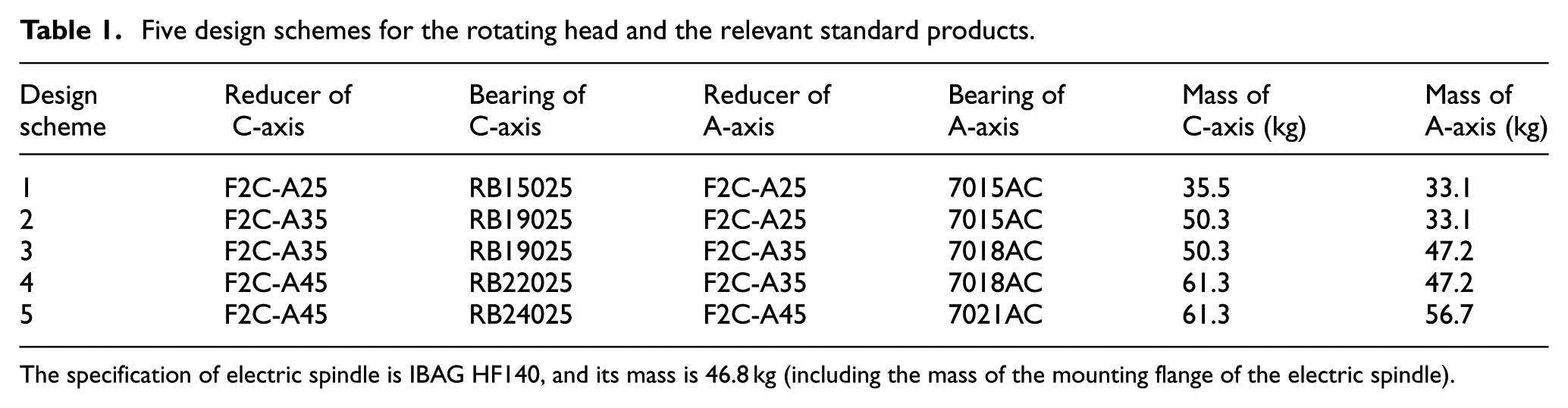
The specification of electric spindle is IBAG HF140, and its mass is 46.8 kg (including the mass of the mounting flange of the electric spindle).
The dimensions, masses, and center of mass locations of the relevant components.

The component compliance coefficients of A-axis in the body fixed frames (unit:
The component compliance coefficients of C-axis in the body fixed frames (unit:
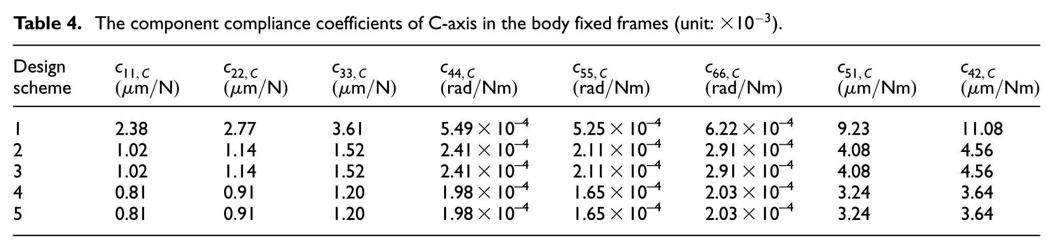
Figure 5 shows the variation of

The variation of
To compare the gravity-induced deflection

By taking scheme 4 as an example, Table 5 shows the deflection at a given configuration (
The deflection, respectively, caused by the cutting forces and gravity at a given configuration.

F Furthermore, the groove milling is used to demonstrate the lightweight design of rotating head by assuming the allowable linear deflection δT to be 0.08 mm. Table 6 lists the maximal deflection within the workspace when considering both groove-milling-induced forces and gravity of components. It shows that the performance of scheme 4 outweighs the other schemes in terms of deflection. Figure 6 shows the distributions of the first four-order nature frequencies of the scheme 4 within the workspace, which indicates that the rotating head has high dynamic behaviors.
The maximum value of the deflection, respectively, caused by the cutting forces and gravity within the workspace.


The distributions of the first four-order natural frequencies of the scheme 4 within workspace
Conclusion
By considering the gravity, this article presents an approach for the compliance analysis and lightweight design of a 2-DOF rotating head. The following conclusions can be drawn:
A linear map is established between the joint reaction forces and the externally applied wrench, including the gravity of components. The gravity of end-effector can be treated as external loads which can cause the elastic deformation of A-axis and C-axis. The gravity of A-axis can cause the elastic deformation of C-axis; however, the gravity of C-axis cannot cause the elastic deformation of A-axis. Hence, it can be concluded that the transmission of gravity is in a straightforward manner, that is, from connected joints to fixed frame.
The method enables to effectively evaluate the end-effector’s deflection caused by the payload and gravity within the given task workspace. The example demonstrates that the gravity-induced deflection initially decreases before inclining with the increase in the specifications of the bearings and gear reducers.
An approach for the lightweight design of a 2-DOF rotating head with excellent static rigidities and dynamic behaviors is proposed by considering the deflection constraints of the end-effector.
Footnotes
Handling Editor: Davood Younesian
Declaration of conflicting interests
The author(s) declared no potential conflicts of interest with respect to the research, authorship, and/or publication of this article.
Funding
The author(s) disclosed receipt of the following financial support for the research, authorship, and/or publication of this article: This research work was partially supported by the National Natural Science Foundation of China (grant nos 51605225 and 51622508), the Fundamental Research Funds for the Central Universities (grant nos 30915118830 and 309171B8808), and the Research Project of State Key Laboratory of Mechanical System and Vibration under grant MSV201812.