
Abstract
To avoid casualties and economic loss caused by vehicle yawing motion during the tire blowout, first, by changing several key parameters of the characteristics, this article uses CarSim software and MATLAB/Simulink to establish a vehicle model of tire blowout based on the UniTire model. This model is implemented to simulate tire blowout caused by the change of the vehicle motion state. Second, considering the driver error and radical-operated steering wheel after tire blowout leads to runaway car problems. This article takes the target trajectory and actual trajectory of error and error rate as the system input; an adaptive fuzzy proportional–integral–derivative controller is designed to determine the vehicle steering wheel angle during the tire blowout and replace the driver to control the direction of the vehicle. The results indicate that the designed controller is capable of ensuring the vehicle constancy and keeping the vehicle on the original track.
Keywords
Introduction
The majority of traffic accidents are caused by tire blowout. According to the statistics from the Ministry of Public Security, tire blowout is responsible for almost 70% of major highway traffic accidents and this proportion has reached up to 80% in the United States. 1 When puncture occurs, serious damage could happen to the vehicles and drivers if correct measures are not taken. Puncture is a process during which the tire loses pressure due to rupture in a fraction of a second (generally less than 0.1 s). Due to the suddenness, short duration, and unpredictability, the vehicle tends to yaw if no measure is taken under the condition that one side of the vehicle has a flat tire. However, the driver might adjust the vehicle direction or slam on the brake to decelerate subconsciously. Nevertheless, the inexperienced drivers are not capable of making correct judgment under simultaneous effect of metal and environmental factors.2,3 In the study of Zang et al., 4 the defects of conventional pneumatic tires with high-speed puncture are described, which could easily lead to wrong manipulation. Therefore, it is of practical significance to reduce accidents caused by tire blowout to ensure personal safety.
Chen and Yeh 5 investigate the car users’ intention to adopt tire pressure monitoring systems. Guo et al. 6 estimate the current running state of the vehicle by establishing the observer, the response of which controls the tire blowout alarm. However, this method only plays an early warning role and cannot fundamentally solve the safety problems. In the study of Zhang, 7 a differential braking method is proposed to avoid vehicle path deviation by adjusting the vehicle rolling motion and ensuring its operation stability. He et al. 8 propose an active blasting blowout coaxial side tire. This method offsets the unbalanced force due to tire blowout by providing yaw reverse turn. Zhang 9 designs a quadratic regulator for stability control of tire blowout vehicle and estimates the optimal horizontal pendulum moment. However, in the literatures mentioned above, the controller is designed based on the ideal 2-degree-of-freedom (DOF) vehicle model. During the actual process of flat tire braking, speed is time-varying and the longitudinal force of the wheel should not be neglected. As a result, the ideal 2DOF model is substantially different from the model used under actual conditions and cannot accurately reflect the authentic blasting situation. A gain-scheduling proportional–integral–derivative (PID) controller is adopted in the work of Yang et al. 10 to handle the trajectory control problem of vehicles during the tire blowout. The parameters of the gain-scheduling PID controller are calibrated under varying speed. Tagesson et al. 11 propose a method to improve the stability of vehicles after the puncture by reducing the scrub radius of heavy vehicles. Wang et al. 12 propose a novel nonlinear control approach to improve vehicle yaw stability and trajectory tracking ability after the tire blowout.
In addition, the problem of tire blowout can also be solved from the prospect of steering angle. Yang et al. 10 study the stability control of tire blasting vehicle by maneuvering the steering wheel. However, the low DOF of the vehicle model leads to poor precision. In the study of Zhu et al., 13 an analytical method compensating the angle of steering wheel is proposed based on differential flatness theory. However, this method partially relies on the driver’s response; the active steering control of the punctured vehicle cannot be fully realized. Wang et al. 14 propose a novel linearized decoupling control procedure with three designed steps for a class of second-order multi-input, multi-output non-affine system. Guo et al. 15 propose a predictive controller based on the differential flatness model. A 3DOF vehicle dynamic model of tire blowout is established with given flat tire outputs. Tao 16 proposes a method to avoid the harmfulness of tire explosion by obtaining real-time information of vehicles and road information.
As far as the above-mentioned literature concerns, this article aims to improve the safety of tire blowout vehicle by realizing active steering control. This article is organized as follows. First, a method of tire-blown vehicles’ stability control is put forward. This method is capable of solving serious yaw problem caused by tire-blown vehicles and ensures the safety of driving. Second, the proposed method is applied to the field of driverless or active driving automobile in the future; 17 Third, the difference of vehicle trajectory is taken as the control input to fuzzy the front wheel angle, as such the deviation correction is realized. The trajectory can be measured directly by sensors, which is convenient and effective, to avoid the difficulties of obtaining control variables, such as side-slip angle and yaw angular velocity. An E-class vehicle is taken as the research object. Based on the UniTire model and the vehicle model established by CarSim, the change of the vehicle state caused by tire blowout is simulated. Then, an adaptive fuzzy PID (AFPID) controller is designed to estimate the steering wheel angle and automatically adjust to proper steering in real time despite the driver. Finally, the left-front and the left-rear tire blowout are simulated by the controller. Simulation results show that the vehicle stays on the original trajectory and maintains the stability well.
Vehicle dynamic modeling with tire blowout
As the only part of the vehicle which contacts the ground, the tire is mainly used to support the body of the car and provide a cushion for impacts from road drive and brake. The change of tire characteristics will directly affect the motion state of vehicle. The UniTire model, which was developed by Guo Kong-hui, is mainly used in vehicle handing and stability simulation analysis. The tire model is established based on the UniTire model for its excellent theoretical boundaries, quick solving speed, and high-precision simulation under complex conditions. The specific formula adopted in this simulation is listed in literature.18–20
The tire adhesion coefficient is assumed to be 1, and the vehicle vertical load is 4500 N. The lateral force and longitudinal force of each tire model are simulated and compared, as shown in Figure 1.

Lateral force and longitudinal force of each tire model.
From the relationship between the longitudinal force and the longitudinal slip ratio demonstrated in Figure 1, it can be seen that the outcomes from all tire models are basically the same in the linear region, but the peak characteristics of the UA-Tire model and the Brush-Tire model are more obvious than those of the UniTire and Magic-Tire models. When the car is in the condition of high slip rate, the UniTire model quickly converges which accurately reflects the state of the tire under extreme conditions. It can be seen from the diagram (right of Figure 1) that when the tire side angle is small, the tire is in the linear region, and the outcomes from all tire models are basically the same. When the tire side angle increases, the tire enters the nonlinear region, and the UniTire model gradually stabilizes at a limit value. The Magic-Tire and Brush-Tire models exhibit a certain degree of deviations under extreme conditions and the UA-Tire model performs well in the aspect of peak characteristics.
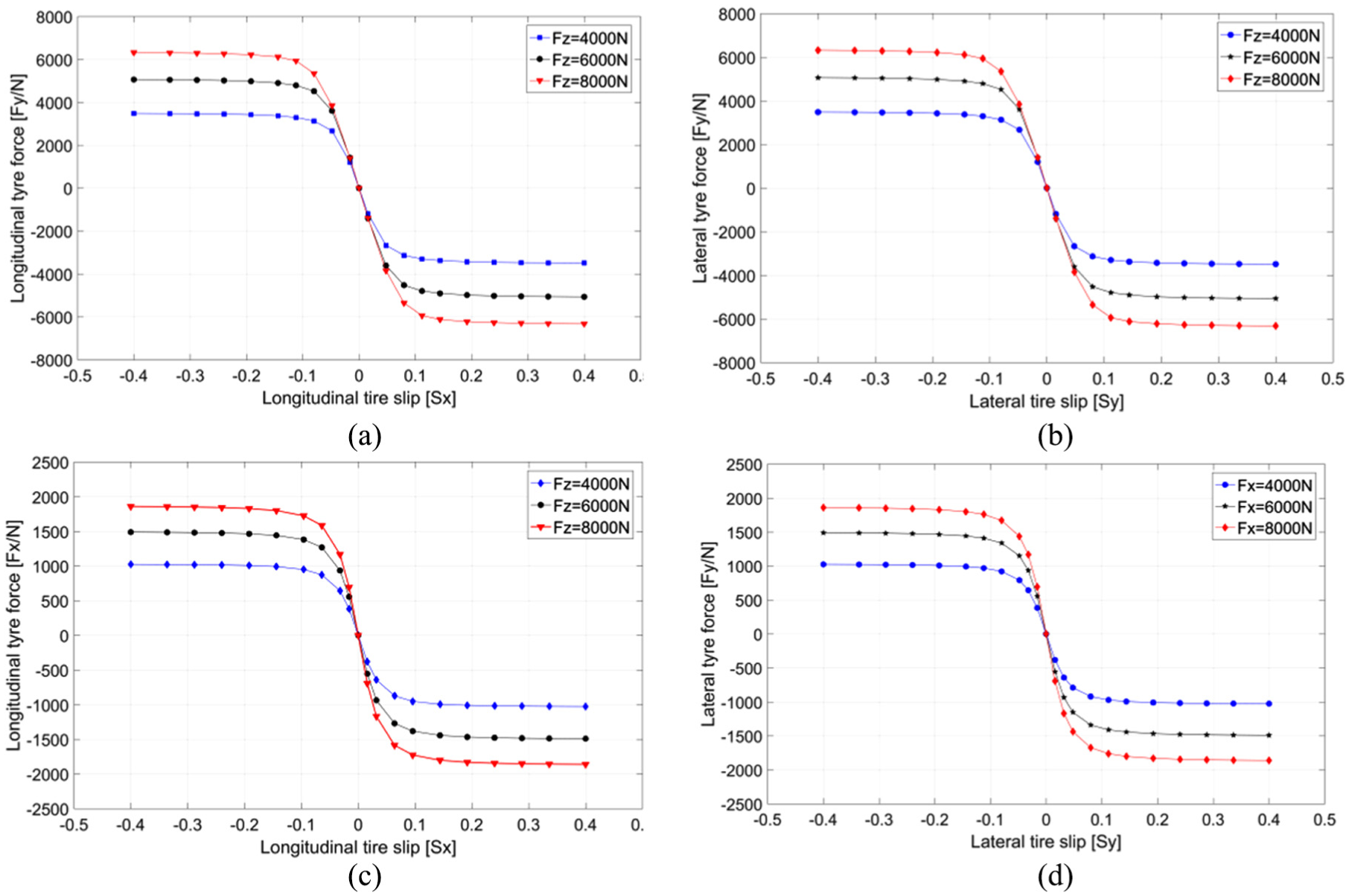
Figure 2 shows the simulated lateral force and longitudinal force of the tire under different vertical loads. As shown in the four diagrams, the lateral force and longitudinal force of the UniTire model stabilized quickly when the slip ratio and side angle are large, which strongly indicates that the UniTire model is suitable for simulation studies under extreme conditions.
Tire tangential force of (a) high friction coefficient road and (b) low friction coefficient road.
Since the actual puncture test is dangerous and costly, the published data are used to describe the post-puncture changes of tire’s characteristics. According to the experimental results from the work of Cai, 21 the impact of tire blowout on tire mainly contains the changes of longitudinal slip stiffness, cornering stiffness, radial stiffness, radius of the wheel, rolling resistance coefficient, and so on. Due to the extremely short duration of tire blowout, the characteristic parameters of tire are simplified to be linear. When tire blowout occurs, the longitudinal slip stiffness, cornering stiffness, radial stiffness, and wheel radius will reduce approximately by 28%, 25%, 1/15, and 2/3, respectively, and the rolling resistance coefficient will increase by 25 times. 21 This process of change is illustrated in Figure 3.
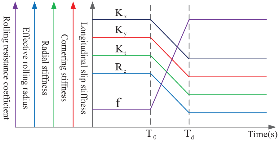
Illustration of changes in properties of the blown tire.
As shown in Figure 3, T0 denotes the time before the tire blowout and Td denotes the time after the tire blowout. The tire blowout process lasts from T0 to Td. Take longitudinal slip stiffness for instance, the among of change during the tire blowout process is
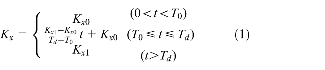
where Kx0 denotes the longitudinal slip stiffness before the tire blowout and Kx1 denotes the longitudinal slip stiffness after the tire blowout. Similarly, according to the relations above, the flat tire model based on UniTire can be established by Simulink.
Considering that the real vehicle puncture test contains a certain degree of danger and has a long development period with high cost, this project uses the vehicle dynamic simulation software CarSim and MATLAB/Simulink to establish a vehicle simulation platform. CarSim software is a graphical user interface (GUI)-based vehicle dynamic modeling and simulation software, the characteristics of which are quick solving speed, good visualization effect, convenient parameter configuration, and high fidelity. The vehicle model has a high DOF (27DOF), which is capable of reflecting the actual vehicle motion state. 22 CarSim’s tire model is based on Magic-Tire model. Compared to other tire models, after analyzing the advantages of UniTire model in dealing with extreme conditions (such as tire blowout), we decided to combine the UniTire model and CarSim model to form the simulation model of tire blowout vehicle. The combined tire blowout model is demonstrated in Figure 4.

Vehicle co-simulation model with tire blowout.
Controller design
Control system design
When the tire bursts, it is the driver’s instinct and natural to adjust the vehicle through the steering wheel. However, in practice, the outcome is always under-steer or over-steer which exacerbates the yaw of the vehicle. In order to solve this problem, this article introduces a reasonable controller to determine the steering wheel angle of the vehicle under tire blowout, which takes over the driver to control the steering. The overall control system flowchart is shown in Figure 5.

Diagram of the control system.
As shown in Figure 5, the analysis results demonstrate that the specific work of the entire control system can be described as follows. When the blowout signal is detected by the tire monitoring system, the blowout signals are transmitted to the decision module and the decision module switches to the control system immediately. Finally, the control system inputs the deviated target trajectory and original trajectory. The error rate is calculated accordingly and transmitted to AFPID controller. As a result, the parameters are real-time adjusted, and the controller determines the steering wheel angle. The vehicle trajectory is automatically controlled through the above steps.
AFPID controller design
Traditional PID controllers are often applied in practical engineering control because of their simple structure and convenient parameter adjustment. It takes the deviation between the actual quantity and the expected quantity as inputs and tracks the expected value through the linear combination of proportion (Kp), integration (Ki), and differentiation (Kd). However, the traditional PID control algorithm is linear, and it is difficult to deal with nonlinear complex system. Moreover, the PID control algorithm can only simulate fixed parameters and incapable of realizing real-time variable parameter control. The system’s demand for parameters under different working conditions (in this article, it means different speeds) could not be satisfied. Therefore, the conventional PID control algorithm is no longer suitable for nonlinear system which works under different conditions. At present, fuzzy control is the most important and widely used form of intelligent control. It makes full use of human’s decision-making behavior and does not depend too much on the precision of the controlled object model, especially for strong nonlinear time-varying system. But a single fuzzy controller has no integral term, so its steady-state accuracy is not high. Thus, the traditional PID control algorithm is usually combined with a single fuzzy controller to form a fuzzy PID (FPID) control. As a result, the FPID controller is chose to control the stability of tire blowout vehicle. The inputs of the AFPID controller are error (e) and error rate (ec). According to the principles of fuzzy control and certain inference rules, the output variables ΔKp, ΔKi, and ΔKd are obtained. The inference rules are determined according to the input variables mentioned above under different conditions (in this article, it refers to the different vehicle speeds). The flow chart of AFPID is shown in Figure 6.

Diagram of the adaptive fuzzy PID control.
According to the design of the AFPID controller, conventional PID controller is used to adjust a certain velocity and PID parameter fuzzy relation. Since highways are mostly straight with very few sharp turns, therefore, this article only considers the performance of straight-line travel. Yu et al. 23 has used PID controller to calibrate control parameters in the running vehicle under high friction coefficient road (μ = 0.85) and it will not be repeated here.
The vehicle is set to straight-line driving at the speed of 120 km/h. After 2 s, left-front tire blowout occurs as an example. According to section “Control system design,” the controller interposes at this time. It inputs the error e and error rate ec and outputs the PID increment parameters ΔKp, ΔKi, and ΔKd. The e and ec which are the inputs of the fuzzy controller are defined to have seven fuzzy subsets (NB, NM, NS, Z, PS, PM, and PB) as well as the outputs ΔKp, ΔKi, and ΔKd. All these values are defined as negative-big, negative-middle, negative-small, zero, positive-small, positive-middle, and positive-big. Referring to the parameter calibration results, the fuzzy domains of the error (e) and error rate (ec) are assumed to be [0, 30] and [0, 5], respectively, and the increments ΔKp, ΔKi, and ΔKd are assumed to be [–5, 5]. The input and output membership functions are triangle membership functions. The basic modified principle of PID control parameters are concluded as follows: 24
When the deviation between actual value and target value is larger, to speed up the system response and prevent the system from overshooting, we should ensure that Kp is larger, Kd is smaller, and Ki should be zero.
When the error and error rate between actual value and target value are moderate, considering the reduction in system overshoot, the value of Kp and Kd should be small and Ki should be reduced relatively.
When the actual value and target value are different, to ensure good dynamic and static characteristics, the value of Kp and Ki needs to be lager. When the system error rate is too big, the Kd should be reduced and it should take a moderate Kd value on the contrary.
Based on the above three analyses, according to the adjustment requirements of PID parameters and combined with the practical operation experience of tire blowout control, the control rules of error e, error change rate ec, and ΔKp, ΔKi, and ΔKd of FPID controller are shown in Table 1.
Specification of fuzzy rules.

NB: negative-big; NM: negative-middle; NS: negative-small; Z: zero; PS: positive-small; PM: positive-middle; PB: positive-big.
The control rules are defined as follows:
Ri: if e is Ai and ec is Bj, thenΔKp is Ck, ΔKd is Dm, andΔKi is En (i, j, k, m, n = 1, 2, …, 7).
After the gravity method for solving fuzzy, substitute the increments in the following formula

According to the control effects influenced by the quantifying factor and scale factor, a series of conclusion can be summarized as follows: (1) The control effect will be greater when the quantifying factor Ke(Kec) gradually increases and the basic field [emin, emax] gradually decreases at the same time. (2) In contrast, the control effect will be smaller when the quantifying factor decreases gradually and the basic field increases gradually. (3) The control quantity will be better with the increase in scale factor Ku; on the contrary, the control quantity will be worse when the scale factor Ku decreases. Therefore, it is significant to select reasonable quantifying factor and scale factor. The quantifying factor and scale factor of the AFPID controller used in this article are 1.
In the process of online running, the controller works according to e and ec under different working conditions and outputs the corresponding increments ΔKp, ΔKi, and ΔKd through the process of preparation, examination, and calculation. Thus, the controller completes the PID parameters’ online adjustment.
Simulation and analysis
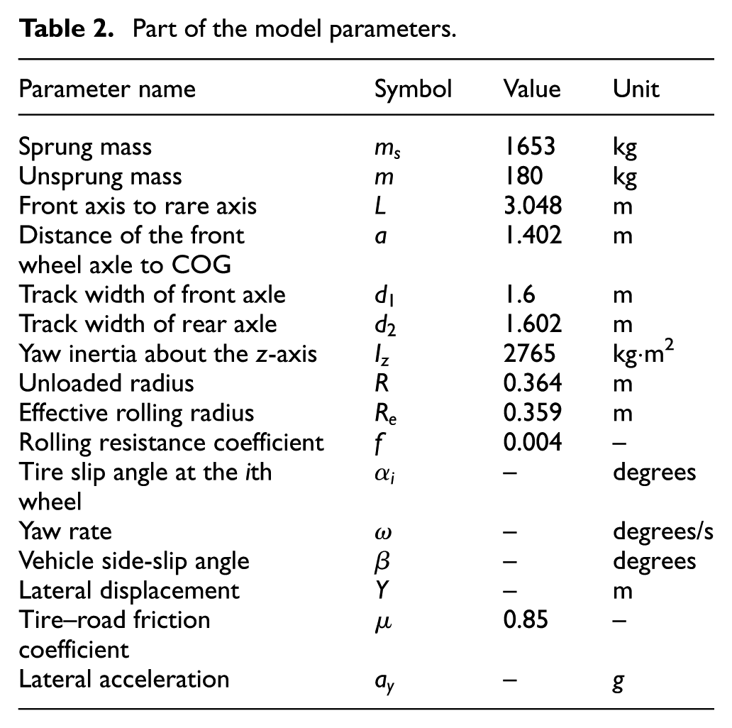
This section investigates the verification analysis of the vehicle model. Some parameters of the vehicle model are listed in Table 2.
Part of the model parameters.
Vehicle model validation
To validate the established vehicle model, three driving conditions are chose: double lane change test, sinusoidal steering test, and high-speed return-to-center test.
Double lane change simulation test
Referring to the ISO standard of “Double Lane Change” of the vehicle model, in this simulation, the vehicle speed and road friction coefficient are set to 70 km/h and 0.85, respectively. The results are shown in Figure 7.
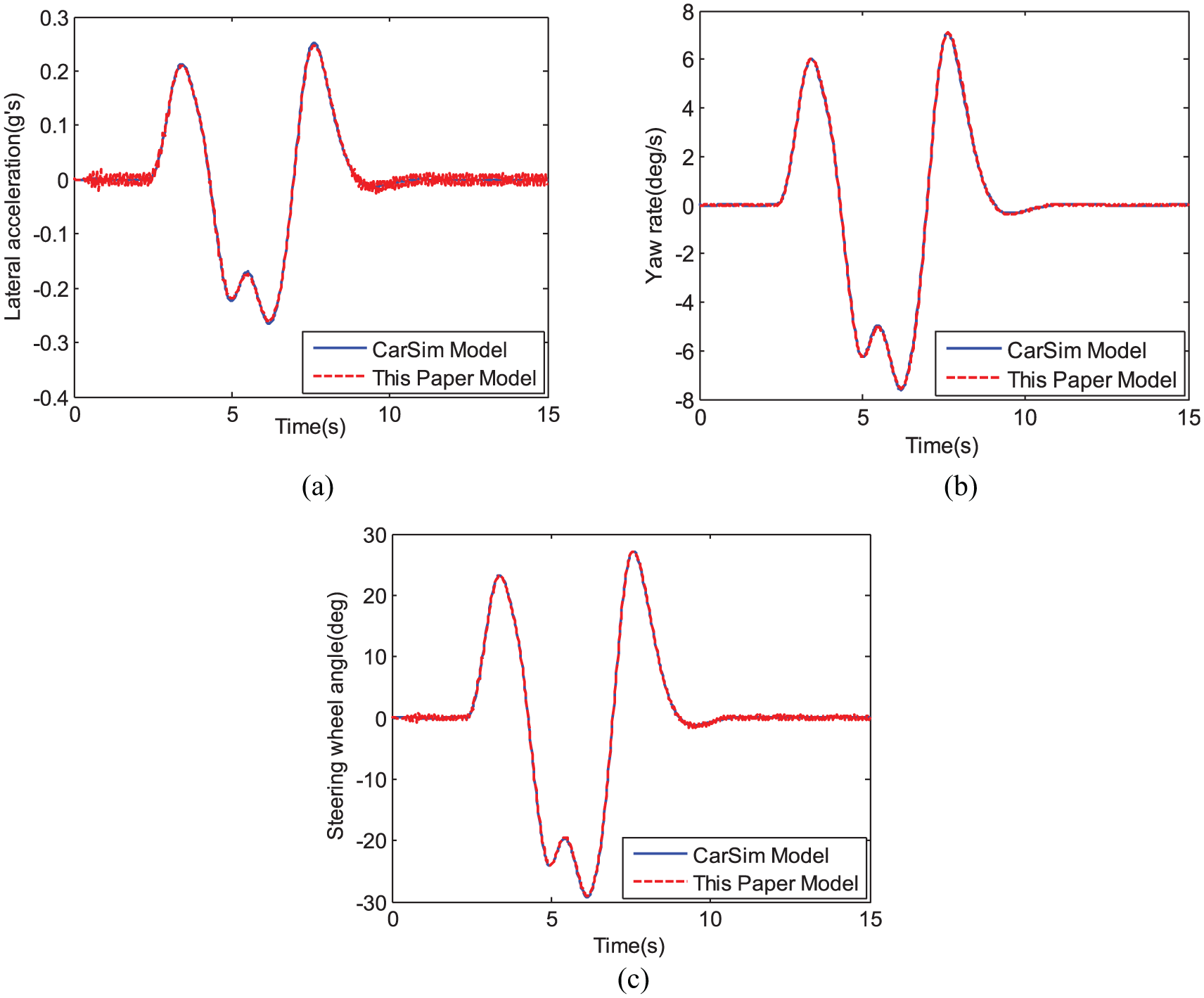
Double lane change simulation test: (a) lateral acceleration, (b) yaw rate, and (c) steering wheel angle.
Sinusoidal steering simulation test
Referring to the ISO standard On Center test, the vehicle speed and road friction coefficient are set to 120 km/h and 0.85, respectively. The input of steering wheel is set to sine input where the amplitude is 20° and cycle is 10 s. The results are shown in Figure 8.

Steering wheel with sinusoidal input simulation test: (a) steering wheel angle and lateral acceleration, (b) steering wheel angle and yaw rate, (c) steering wheel torque and yaw rate, and (d) steering wheel angle and steering wheel torque.
High-speed return-to-center simulation test
Referring to the vehicle handling stability test method (GB/T6323.4-1994), the vehicle speed and road friction coefficient are set to 120 km/h and 0.85, respectively. The torque of the steering wheel is fixed as 6 Nm and the steering wheel is released in 2 s. The simulation results are listed in Figure 9.

High-speed returnability test: (a) yaw rate and (b) lateral acceleration.
From Figures 7–9, we can see that the combined simulation model established in this article is well capable of adapting CarSim software under different conditions. As such, the vehicle model can be used to represent the dynamic response of the vehicle.
State analysis of vehicle motion with tire blowout
Based on the joint simulation of vehicle model and tire model, the tire blowout procedure can be simulated and analyzed as below.
Due to vehicle symmetry, this article simulates the left-front tire blowout and left-rear tire blowout. The impact of tire blowout on the vehicle is observed via the simulation diagrams. In this simulation, the vehicle travels along the straight line at the speed of 120 km/h, and the road friction coefficient is set to be 0.85, the left-front tire or left-rear burst after 2 s. The speed remains to be unchanged and the steering wheel adopts zero correction. Simulation results are shown in Figure 10.

Simulation results of the motion states with the left-front tire blowout and left-rear tire blowout for straight-line driving vehicle: (a) trajectory following, (b) lateral acceleration, (c) yaw rate, (d) side-slip angle, (e) yaw angle, (f) steering wheel angle, (g) tire slip angle (left-front tire blowout), (h) tire slip angle (left-rear tire blowout), (i) simulation of 3D animation (left-front tire blowout), and (j) simulation of 3D animation (left-rear tire blowout).
The simulation results show that in the absence of steering and braking (without driver intervention), it can be seen from Figure 10(a), (e), (i), and (j) that after the tire blowout at 2 s, the vehicle trajectory, yaw angle shift left, and the front tire blowout produce greater offset than the rear tire blowout. In Figure 10(b)–(d), the vehicle state changes obviously after tire blowout, and the value of lateral acceleration, yaw rate, and side-slip angle becomes maximum when the tire blowout occurs. In Figure 10(g) and (h), the wheel side-slip angle changes little, and the rim and matrix are not separated, so it will not cause rollover by the rim card.
In summary, we conclude that if the driver does not modify the steering wheel timely after the tire blowout, according to the highway construction standard, 25 the vehicle will skid off the lane in approximately 1.5 s. But in practice, due to panic and other factors, it is difficult for driver to control the tire blowout vehicle properly.
PID and AFPID control simulation
From section “State analysis of vehicle motion with tire blowout,” the analysis results show that without driver’s reasonable intervention, the vehicle will be in a very dangerous situation. Therefore, this section uses the PID controller and the AFPID controller established in section “Controller design,” respectively, under single speed and different speeds to control the tire blowout vehicle.
1. Condition 1. The vehicle travels along the straight line at the speed of 120 km/h, and the road friction coefficient is set to 0.85. The left-front tire blowout after 2 s, without controller, with PID controller, and with AFPID controller, is simulated and analyzed, respectively, as shown in Figure 11.

Control effect of the left-front tire blowout: (a) trajectory following, (b) lateral acceleration, (c) yaw rate, (d) side-slip angle, (e) steering wheel angle, and (f) simulations of 3D animation (with AFPID controller).
As shown in Figure 11(a)–(d), after the left-front tire burst at 2 s, the vehicle deviates to the left, the lateral acceleration and yaw rate increase rapidly, and the vehicle state becomes unstable.
When the PID controller is implemented, the vehicle immediately rectifies the deviation and controls the trajectory offset within 1 m, but it takes longer time to return to the centerline (Figure 11(a)). It can also be seen from Figure 11(b)–(d) that the time for each parameter to approach zero is extended. Although the yaw rate eventually approaches to 0, it does not reduce the peak value but increases the vehicle instability at the time of tire explosion. Thus, it is concluded that the effect of the PID controller is limited, and it appears to be an overshoot phenomenon.
If the AFPID controller is adopted, the vehicle trajectory after tire blowout is basically straight. The vehicle lateral acceleration peak decreases from 0.15 to 0.08 g, yaw rate reduces from 5.5 to 4 degrees/s, and side-slip angle reduces from 0.5° to 0.3°. Figure 11(e) shows the AFPID controller which determines the steering wheel angle.
2. Condition 2. The vehicle travels along the straight line at the speed of 80, 100, and 120 km/h, respectively, and the road friction coefficient is assumed to be 0.85. The left-front tire has a blowout after 2 s. Changes in various parameters of the vehicle with PID controller are simulated and analyzed.
As shown in Figure 12(a), when the PID controller is adopted, the vehicle rapidly corrects deviation after tire blowout. But with the increase in speed, the difference between the control performances is not significant. From Figure 12(b)–(d), it can be seen that the stability effect of PID control of tire burst vehicle at different speeds is not ideal, and even overshoot (Figure 12(c) and (d)) occurs. The main reason is the immobilization of PID parameters.
3. Condition 3. The AFPID controller is adopted using the same parameters as condition 2. Figure 13 exhibits various parameters in the simulation and the difference between the PID controller and the AFPID controller.
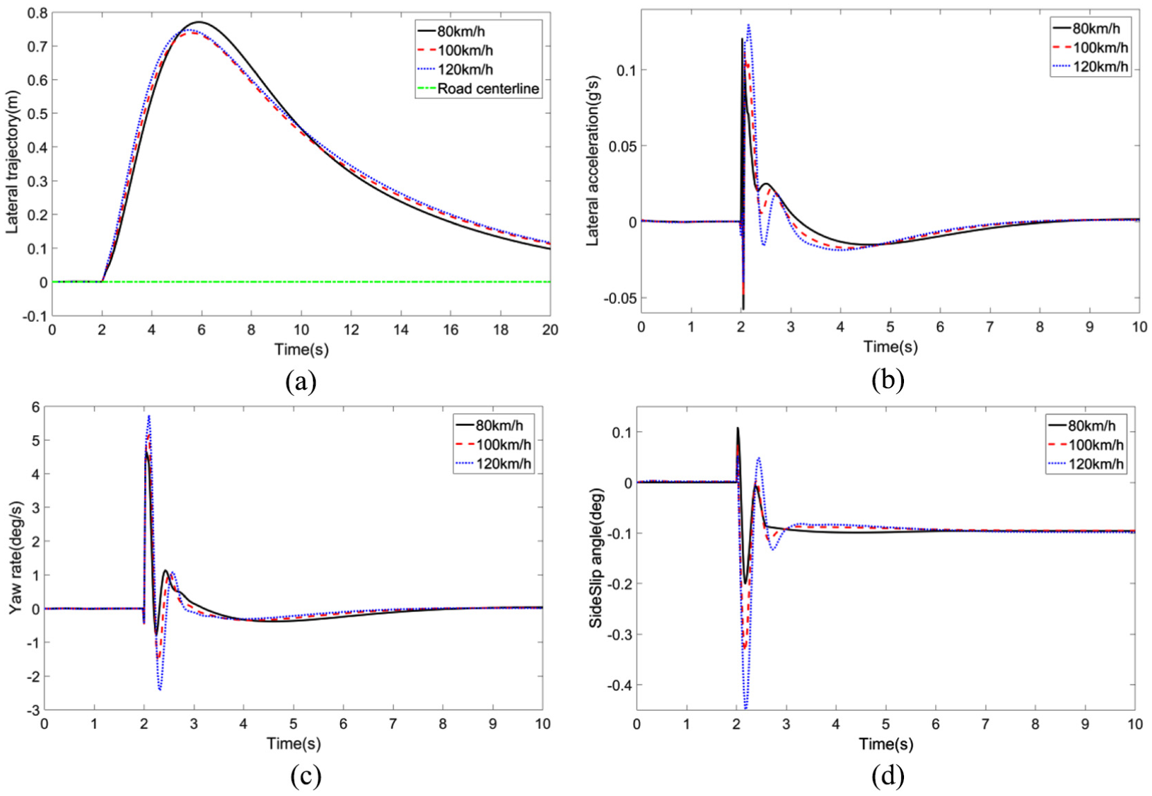
Control effect at various speed of the left-front tire blowout: (a) trajectory following, (b) lateral acceleration, (c) yaw rate, and (d) side-slip angle.
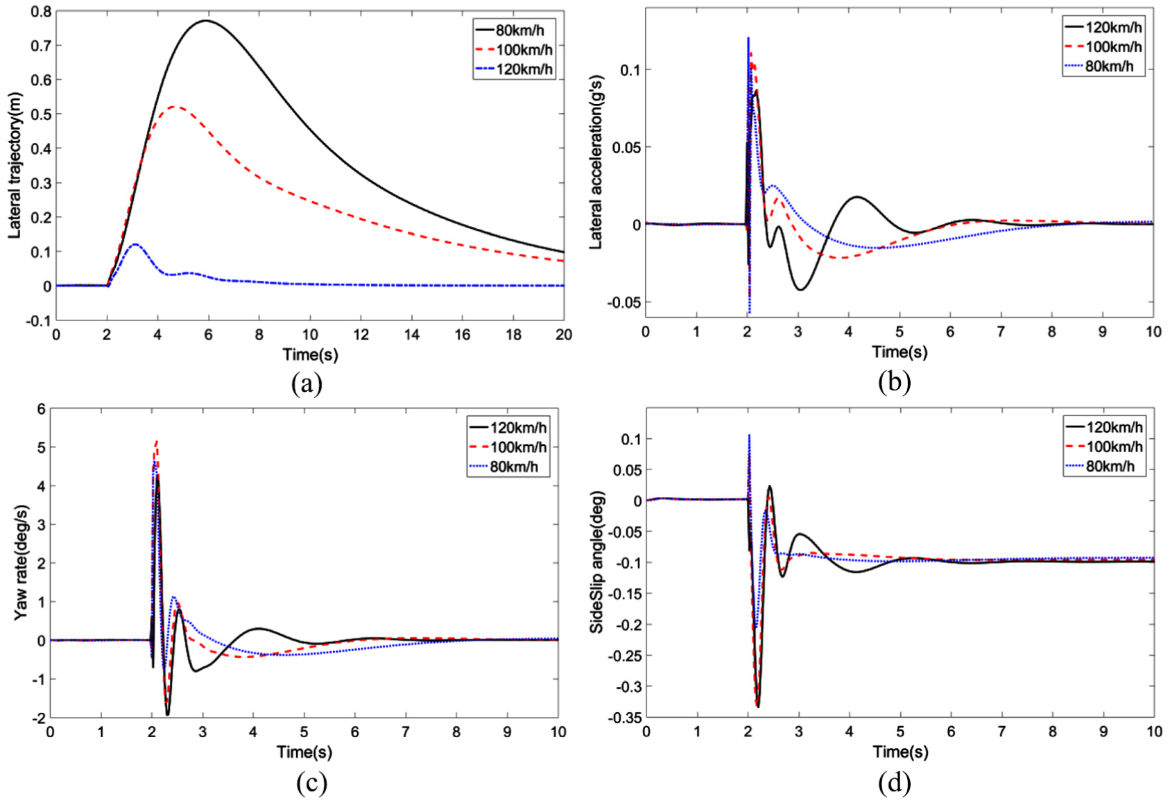
Control effect at various speed of the left-front tire blowout: (a) trajectory following, (b) lateral acceleration, (c) yaw rate, and (d) side-slip angle.
As shown in Figure 13(a), when the AFPID control is applied, the trajectory deviation is small and within allowable range under different speeds after the tire blowout. Eventually, the vehicle travels along the center line of the road. Figure 13(a)–(d) indicates that the vehicle stability parameters are all controlled in a small range, and in the range of driving safety indicator, vehicles with punctured tire are not at risk of tipping over or rim touching the ground.
However, with the increase in speed, it takes longer time to stabilize each performance indicator. As a result, the adjusting time becomes longer. This phenomenon indicates that compared to the low-speed flat tire, it is more difficult to stabilize the vehicle at high speed.
To summarize the above analysis, the PID controller is relatively effective on deviation correction and stability control of the vehicle with punctured tire, but the outcome of stability control is not ideal, which easily tends to overshoot. Compared to the FPID controller, it achieves excellence in performance even when the speed of the vehicle is high and the degree of deviation correction is large with prompt response on vehicle stability control.
Conclusion
The changes in the tire characteristic parameters are the direct cause of the vehicle motion. The mechanical properties change after the tire blowout. Unbalanced tire force produces the yaw torque which affects vehicle’s driving stability. When one side of the tire has a blowout, the vehicle’s trajectory and yaw angle shift to the other side, and the front tire blowout produces a greater offset than the rear tire blowout.
In this article, the AFPID controller is established to determine the steering wheel angle of the vehicle on tire blowout. It takes over the driver and determines the direction of the vehicles, which prevents the driver from operating the steering wheel incorrectly and improves driving safety.
Two main points are listed for future research. First, the electric power system (EPS) can be considered to be implemented in the stability control of tire blowout vehicle. The FPID active deviation correction controller is introduced in the previous paper but not extended to EPS system for research yet. Therefore, further research needs to extend EPS to the active steering safety control of tire-blown vehicles, and achieve deviation correction and stability control of tire-blown vehicles by means of cylinder braking deceleration. Second, real vehicle experiments need to be considered in further research. Due to objective reasons and the risk of puncture, this article mainly studies the dynamic response of the tire, the estimation of the vehicle state parameters, and the safety control of the puncture vehicles from the perspective of modeling and simulation. The real vehicle experiment is the most effective way to verify the algorithm. Therefore, it is necessary to perform the actual vehicle test with the guarantee of safety.
Footnotes
Handling Editor: Xiaodong Sun
Declaration of conflicting interests
The author(s) declared no potential conflicts of interest with respect to the research, authorship, and/or publication of this article.
Funding
The author(s) disclosed receipt of the following financial support for the research, authorship, and/or publication of this article: This work was supported by the National Natural Science Foundation of China (grant nos 51705190, 51705058, 51807019, and 11802047), Chongqing Research Program of Basic Research and Frontier Technology (cstc2016jcyjA0574), and Chongqing Education Commission (KJ1600423).