
Abstract
In this research study, the characteristics of ship–bridge collision force formulas, in Chinese standards as well as international standards, were analyzed. By considering the damage situations of bridge piers under the cumulative ship collision conditions, a method of combining theoretical deduction with numerical analysis was adopted in this study. The goals of this study were to analyze and examine the sizes of the ship–bridge collision forces, along with the damage situations of piers, in order to propose a collision force calculation formula which took cumulative pier damages into consideration. Also, experimental verifications and an applicability analysis of the proposed formula were performed.
China’s transportation industry has vigorously grown with the continuous development of the country’s economy. As an important part of the traffic infrastructure measures, the number and scale of China’s bridges have also been continuously increasing. Moreover, the waterway transport demands have expanded. All of these factors have led to frequent occurrences of ship–bridge collision accidents, which have resulted in significant economic losses and security risks. Therefore, it has become necessary to fully take into consideration the bearable sizes of collision forces in the designs and construction of bridges, in order to avoid damages to bridge structures resulting from ship–bridge accidents which potentially endanger the safety of life and property. In real situations, there will always be certain damages incurred by piers following ship collisions. Therefore, improved methods for evaluating the collision resistance performances to cumulative collision damages of reinforced concrete piers have become key focuses in the field of marine bridge construction.
Previously, the research methods for examining pier collision forces have mainly included formula and numerical simulation methods. For example, G Woisin (Germany) used a series of theoretical studies and model tests to propose the Woisin formula. Pedersen et al. assumed that colliding ships only interacted with piers at the collision points and then, using four linear equivalent springs to simulate all the deformations which appeared near the collision points, proposed the Pedersen formula. The standard formulas which are used in China and internationally have also become increasingly thorough, such as the American Association of State Highway and Transportation Officials (AASHTO) and the European standard formulas, as well as China’s Fundamental Code for the Design of Railway Bridges and Culverts, the General Code for the Design of Highway Bridges and Culverts, and so on.1–6 The aforementioned numerical simulation methods use computer finite element general software to conduct collision simulations. These methods have been widely applied due to such advantages as low cost, high repeatability of testing, and simplicity of applying boundary conditions. J Liu and Y Gu 7 and Hu et al. 8 successively used finite element software to simulate the situations when ship–bridge collisions occur under different conditions and were able to obtain more accurate data regarding maximum ship–bridge collision forces. Consolazio and Cowan 9 established a finite element analysis model to study the influences of pier sizes and shapes on the collision forces. YY Sha and H Hao 10 applied finite element software to establish numerical models of ship–pier collisions and established an empirical formula for predicting ship damage depths and peak collision forces. Zhang et al. 11 used the analytical and finite element analysis methods to study model-scale and full-scale collision tests, so as to further quantify the key calculation parameters. Zhou and Huang 12 used the finite element software program ABAQUS to perform numerical analysis, so as to obtain the maximum collision force, thereby simplifying the calculation formula.
The current studies regarding ship–bridge collisions both in China and internationally are generally based on the condition that it was the first time that the bridge piers had suffered a collision. These studies have not considered a collision force calculation under damaged state conditions after a bridge structure has been subjected to multiple collisions. In reality, bridges have often suffered many different degrees of collisions. Therefore, large errors will occur if the calculations are made directly using the existing standard formulas which are currently used both in China and globally. Among these standard formulas, the material properties of the ships and piers are only involved in the European standard formulas, as well as the codes of railway bridges and culverts in China. However, the effects of pier damage situations and cumulative collisions on the collision force calculations have not been further discussed. Therefore, the aforementioned standard formulas are not suitable for the calculations of cumulative collisions. At present, the impact damage of bridge piers is mainly identified by the ultrasonic non-destructive testing method.13,14 In this study, the damage situations of bridge piers were considered under the conditions of cumulative ship–bridge collisions. Then, based on the law of conservation of energy, ultrasonic sound velocity is used to evaluate pier damage, and a method of combining theoretical deduction with numerical simulation was adopted in this study to analyze and examine the sizes of the collision forces and damage situations of bridge piers. A calculation formula for collision forces which included damage effects under the conditions of cumulative ship–bridge collisions was proposed. Then, experimental validations and applicability analysis were conducted, which provided valuable technical support for evaluating the cumulative collision damages of bridge piers.
Establishment of a collision force formula based on damage effects
Analysis of the basic formula
In this study, ship–bridge collision processes were analyzed and deduced, as shown in Figure 1. Then, by assuming that the stiffness coefficients of the pier and ship were k1 and k2, at the moment when the ship collided with the pier, the ship mass is m, velocity is v, pier and ship deformation are Δ and δ, and F is the impact force of the collision. Then, the following formula was found to meet at the moment of collision between the ship and bridge pier


Schematic diagram of the ship–bridge collision.
The collision force calculation formula could be obtained based on
Among the standards used in China and internationally, calculation formulas for ship–bridge collision forces under certain conditions have been given. However, these standard formulas are generally applicable to the calculation of collision forces under the conditions of first collisions between ships and bridges. However, during the actual combinations of production and real-life situations, many small-scale collisions occur to the ships and bridges, which require the examinations of the sizes of the corresponding collision forces, along with the damage situations of piers following cumulative multiple ship–bridge collisions.
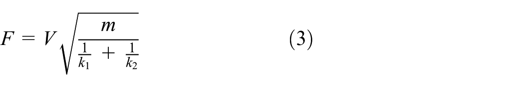
In the aforementioned European standards, the formula is based on a single-degree-of-freedom (SDOF) rigid body collision hypothesis, in which the kinetic energy of a ship is transformed into the elastic potential energy of the prow during a collision. The stiffness of the prow is simulated by a spring, and the total mass of the ship during a collision event is simulated by the concentrated mass. Therefore, the following formula can be obtained from the energy conservation results

where V is the velocity (m/s) of the collision body at the time of collision, M is the mass of the collision body, and K is the equivalent stiffness of the collision body (MN/m).
In the above-mentioned European standard formulas, the equivalent stiffnesses of the collision bodies are considered. However, the pier stiffnesses are not considered, and the bridge piers are greatly influenced by the collision impacts during the ship–bridge collisions. At the same time, the piers have also been the main research objects of the collision events. Therefore, these standard formulas are insufficient for the examinations of the collision forces of bridge piers which have sustained cumulative collision damages.
In China’s code for railway bridges and culverts, the collision forces of ships or rafts to bridge piers is calculated by assuming that the effective kinetic energies of the ships or rafts are all converted to the static processes of the collision forces. This method is generally referred to as the “static method,” and the collision forces can be calculated according to the following formula

where
The formula of the collision force calculation given in China’s code of railway bridges and culverts considers the impacts of the elastic deformation coefficients of the ships and piers on the sizes of the collision forces. When compared with the formula of the collision forces derived from the law of conservation of energy, this standard formula also considers the fluid effects and influences of the ship–bridge collision angles while more comprehensively and judgmentally examining the ship–bridge collision problems. However, this standard formula is also used under the conditions of first-time ship–bridge collisions, without consideration given to the damage situations of the piers. Therefore, this study conducted a further derived examination of this formula.
Damage factors
It was found that, in the current standard formulas, there have been no specific explanations given for the elastic deformation coefficients
At the present time, several effective methods for the definitions of damage variables are used, including methods based on effective sections, elastic modulus, and ultrasonic velocity. The results of this study showed that the velocities of the ultrasonic waves in a material are closely related to the elastic modulus and other properties. After the material becomes damaged, the elastic modulus of the material will change, and the velocities of the ultrasonic waves will also be affected. Therefore, the damage variables of the material can be defined by the changes in the wave velocities, in order to further judge the material damage situations and define the damage factor D 18

where
Examination of the K–V2 relationship
Theoretical research
It was ascertained from the material mechanics that the stiffness K and elastic modulus E conformed to a primary function relationship

The relationship between the wave velocity and elastic modulus 19 in solid media when ultrasonic instruments are used to measure the damage process is as follows

where
The following was then obtained using formulas (7) and (8)

According to formula (9), the elastic deformation coefficient
Numerical simulation analysis
ABAQUS software was used for numerical analysis in this study, in order to further illustrate the relationship between K and V2 of the pier after the collision damages occurred, mainly including the following aspects:
Model constitutive selection. In the study of the ship–bridge collision problem, the selection of the concrete constitutive model is very important. In this article, the concrete damage plastic model is used to perform numerical modeling analysis, 20 which features an extremely convenient way to define the parameters. The input of elastic modulus and Poisson’s ratio of the model specimen can satisfy the calculation. For the constitutive aspect of reinforcement, the ABAQUS software program includes the plastic kinematic hardening model of the longitudinal reinforcement and stirrups. 21
Connection method of reinforcement and concrete parts. In ABAQUS, the methods for establishing reinforced concrete structure models include integrated, separated, and combined types. Separated modeling considers the interaction between concrete and reinforcement, reflecting the joint effect of the two on the model as a whole. The steps in the model are relatively complex, yet advantageous for simulating the state under actual conditions, and thus a separated model is used in this article.
Meshing. The quality of meshing has a great impact on the simulation results. In ABAQUS, there are ways to sweep and freely mesh. Since the structure simulated in this article is a relatively complex physical unit, a freely meshing method is adopted. The meshing situation is shown in Figure 2.
Boundary conditions and load application. The definition of boundary conditions and loads is a key part of the numerical simulation. Considering the actual engineering, the corresponding model tests for ship collision accidents in both China and other countries adopt high-strength bolt-fixed connection. Therefore, in this model, the fixed constraints in all directions are selected at the bottom of the pier. At the top of the pier, an equal axial uniform load is applied on the top surface of the cylinder. For the trolley in the test, the freedom of the ship in all directions except the X-axis direction is restricted, according to the actual situation.
Model calculation. The test speed value is given in the X-axis direction of the ship, and the ship–pier collision movement is realized via the analysis step function.

Reinforcement meshing effect.
In order to examine the relationship between the collision forces and elasticity modulus, the collision force curves and displacement curves under different values of elastic modulus E were obtained by changing the elasticity modulus E of the pier during the numerical simulation, as shown in Figures 3 and 4.

Collision force–E curve.
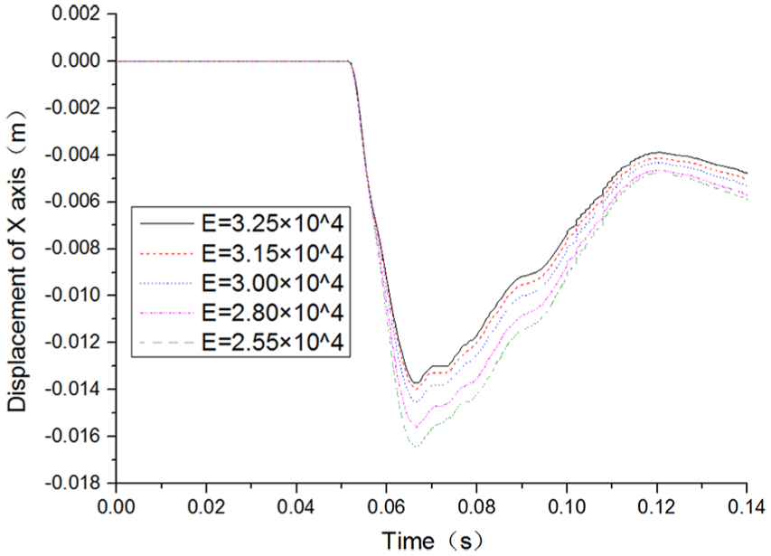
Displacement–E curve.
Through the above-mentioned curves, it was assumed that the “load–deformation” of the pier indicated a primary linear relationship, in which C2 represented the elastic deformation coefficient of the pier, F represented the collision force, and the relative total displacement of the collision point along the direction of the normal velocity was denoted by Δ.
Then

The elastic deformation coefficient C2 of the bridge pier can be calculated, and the reciprocal K2 is the stiffness coefficient of the pier. It is known that ultrasonic waves are used to detect concrete members, and the relation (equation (8)) between the wave velocity Vb and elastic modulus shows that the density of conventional concrete is 2500 kg/m3. The calculation of each parameter is shown in Table 1.
Relation between each parameter.

Comparing the collision forces of specimen at E = 3.25 × 10⁴ in the above figure and the undamaged case with the same speed, it is found that the simulation result is close to the test result (relative ratio: 8%), thus validating the accuracy of the numerical simulation analysis. The relationship between the pier stiffness coefficient K and the squared wave velocity
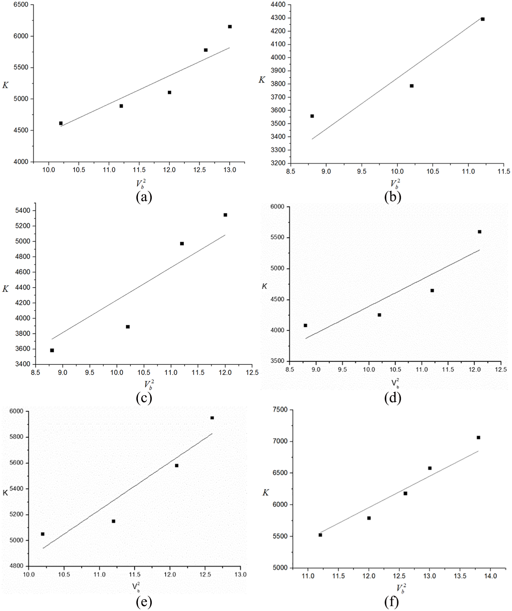
In this study, using a numerical simulation, it was determined that the relationship between
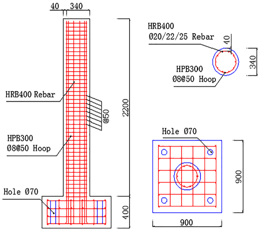
Specimen reinforcement drawing.

(a) Multi-functional ultra-high heavy drop hammer tester system, (b) horizontal-traction collision test vehicle, (c) vertical drop weight device, (d) pressure sensor, and (e) laser speedometer.

Restraint device.
Formula for the collision forces of the cumulative collision damages
In this research study, through the numerical analysis of the concrete piers with different strength grades, it was determined that

It was ascertained in this study that, in the codes for railway bridges and culverts in China, the involved

Therefore, the elastic deformation coefficient
Then, in accordance with the damage factor

Following the ship–bridge cumulative collision, after considering the damage factor D, the collision force formula was obtained as follows

where
Collision test verification process
In order to further verify the practicability of this study’s collision formula, a corresponding collision test was designed and performed.
Test process
A total of five scale (5:1) specimens for ordinary reinforced concrete circular bridge pier were designed in the test. In order to verify the wide applicability of the formula, the diameter and number of longitudinal reinforcements of the specimens are not exactly the same, that is, the specimens have different reinforcement ratios. The specimen number and design parameters are detailed in Table 2. The specimen has a column cross-section radius of 170 mm and a height of 2200 mm. The longitudinal reinforcement consists of HRB335 reinforcement, and the stirrups are made of 8-mm-diameter Grade I ordinary reinforcement HPB300. The welding construction is conducted, as shown in Figure 6.
Specimen number and design parameters.

The multi-functional ultra-high heavy drop hammer tester system is used in the collision test, as shown in Figure 7(a). The kinetic energy of the horizontal collision test vehicle (hereinafter referred to as the trolley, as shown in Figure 7(b)) is provided by the vertical drop hammer driving system (as shown in Figure 7(c)). The size of the trolley is L×W×H= 2.08 m × 1.15 m × 0.64 m, and the mass is 1.2 t. The front end of the trolley is equipped with a rigid impact hammer, and there are four specially designed steel cylinders between the hammer and the trolley. The collision force of the trolley when the pressure sensor is mounted is shown in Figure 7(d). The end of the track is equipped with a laser speed measurement system to measure the instantaneous velocity at impact, as shown in Figure 7(e).
Prior to testing, the pier specimen was fixed to the rigid base by four prestressed bolts, which was approximately equivalent to the solid end constraint. The upper end of the column is subjected to an axial pressure of 250 kN by a hydraulic jack mounted on the beam of the reaction frame, as shown in Figure 8. After installing the reinforced concrete column specimens, the drop hammer was then lifted to the appropriate height for impact testing. In order to investigate the influence of the pier damage on the impact force, Specimen M1-20 was impacted at a constant speed (i.e. the speed of each impact remains approximately equal), and the impact speeds of the remaining specimen were successively increased. After the impact, the damage of the specimen was measured with an ultrasonic detector.
Test result analysis
The experimental results of the speed of the ultrasonic non-destructive testing are shown in Table 3 and Figure 9.
Mean wave velocity of the specimen.


Ultrasonic wave detection oscillogram.
Figure 10 displays the collision force curves collected from test columns M3-20 and M3-22 in the collision test.

Impact time history curve: (a) M3-20, V = 2.489 m/s; (b) M3-20, V = 3.083 m/s; (c) M3-22, V = 2.601 m/s; and (d) M3-22, V = 3.221 m/s.
The data results which were collected from each test column were compared with the results of the calculation formula, as shown in Table 4.
Comparison of the column test results using the proposed calculation formula.
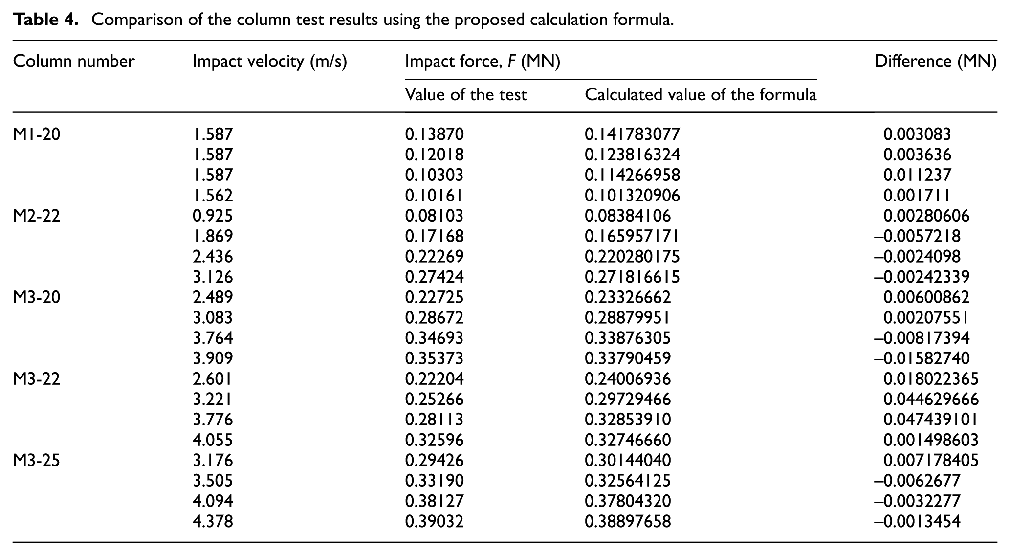
It can be seen from the above table that for Specimen M1-20 the impact speed is approximately equal each time, but the impact force is gradually reduced, due to the loss of specimen rigidity caused by the impact damage. It is shown that the damage of the specimen has an influence on the impact force. In addition, as the number of impacts increases, the relative ratios of the impact force (test value) containing the damage to that without the damage are 1.797%, 3.567%, and 3.709%, respectively. It can thus be seen that as the damage degree of the test piece increases, the impact force becomes smaller and smaller, so that the influence of the damage on the specimen must be considered when calculating the impact force. Combined with other test pieces, it can be determined that the calculation results obtained using the formula proposed in this study were similar to the test results, and the difference range was between 0.00135 and 0.0473 MN. It can be seen that the proposed formula had more effectively reflected the collision force sizes when the collisions had occurred after considering the damages incurred during the cumulative collisions of the pier and thus provided certain applicable values.
The results of the collision force formula containing the damage factors proposed in this study were compared with the standard formulas which did not consider the cumulative damages to the piers, as shown in Figure 11.

Sensitivity curves: (a) M3-25, (b) M3-22, (c) M3-20, and (d) M2-22.
After a comparison of the figures was completed, it was found that the influences of the structural damages on the collision forces tended to increase after multiple accumulative collisions. Also, when compared with the standard formulas, the formula proposed in this study considered the influences of the damage factors. The differences were found to have gradually increased with the accumulation of the collision damages. In other words, the higher the damage degree of the structures was, the more accurately the proposed formula reflected the sizes of the collision forces. Furthermore, when compared with the standard formulas, the formula curves in this study were observed to be more consistent with the experimental curves, which also better reflected the collision forces following the collision damage events.
Conclusion
In this research study, under the conditions of cumulative ship–bridge collisions, a calculation formula for the collision forces containing damage factors was proposed. The results of this study’s experimental testing further confirmed the reliability of the proposed formula through a series of numerical analyses. Then, in order to verify the applicability of the proposed formula, comparisons with the actual test results and the current standard formulas were completed. The main conclusions which were reached in this study were as follows:
As the impact damage of the pier is increased, the impact force is gradually reduced and the impact of the damage must be considered in the calculation of the impact force.
Under the conditions of the ship–bridge cumulative collisions, this study proposed a collision force calculation formula containing damage factors after considering the pier damage situations.
The proposed collision force formula containing damage factors was found to be in good agreement with the actual test results. Therefore, the proposed formula presented a certain applicability potential due to its ability to more effectively meet the actual computational demands.
Footnotes
Handling Editor: Farzad Ebrahimi
Declaration of conflicting interests
The author(s) declared no potential conflicts of interest with respect to the research, authorship, and/or publication of this article.
Funding
The author(s) disclosed receipt of the following financial support for the research, authorship, and/or publication of this article: This research was sponsored by the Science and Technology Innovation Project of Department of Education of Guangdong Province (2013KJCX0188), the Major Project (Natural Science) of Department of Education of Guangdong Province (2014KZDXM064), and the Civil Engineering Technology Research Center of Guangdong Province.