
Abstract
Currently, a large number of elevator manufacturers do not consider the actual impact speed during the selection of buffers or the calculation of guided travel, which creates safety risks. By analyzing relevant standard situations, this article establishes equations to calculate the impact speed of the elevator car or counterweight, determines the corresponding results, and carries out relevant test verifications. Moreover, the influences of buffer clearance on elevator safety are analyzed. Finally, the paper proposes new rules for buffer selection and a new method for calculating the maximum buffer clearance between the buffer and car (or counterweight), which will improve the safety of elevators in actual applications.
Introduction
The distance between the counterweight (or car) and buffer is an important parameter that is closely related to the installation and use of elevators. Moreover, when this distance is beyond a certain range, it can affect the safe operation of an elevator. However, the number of studies carried out on this topic is limited.
According to article 5.2.5.6.1.1 of EN 81-20:2014 Safety Rules for the Construction and Installation of Lifts-Lifts for the Transport of Persons and Goods, the guided travel of an elevator car (or counterweight) without compensating ropes or an antirebound device at the highest position shall be in accordance with the following calculation: counterweight on a fully compressed buffer + 0.035 · v2 (or car on a fully compressed buffer + 0.035 · v2), in which 0.035 · v2 is half the gravity stopping distance corresponding to 115% of the rated speed of the elevator. According to article 5.2.5.6.1.2 of EN81-20:2014, the value of 0.035 · v2 may be reduced by accounting for the speed at which the car or counterweight comes into contact with the buffer. 1
Papers2–5 proposed a method for calculating the maximum distance between the counterweight and buffer; however, this method is based on the requirements of EN81-41:2010, which states that the impact speed should not exceed 115% of the rated speed of the elevator.2–5 Yan‘e 6 proposed a viewpoint wherein the speed at which the car or counterweight comes into contact with the buffer may exceed 115% of the rated speed of the elevator. 6 Miralbes et al. 7 focus on the impact speed on physical health when the car hitting the buffer. 7 The authors of papers6,7 also established a simple equation to calculate this impact speed. However, this method fails to take into account the system acceleration of the elevator in the process of selecting the buffer and calculating the maximum guided travel, which is inconsistent with the actual situation. Moreover, the above articles, and the authors of this article, agree that the speed of the car (or counterweight) will continually increase until it impacts the buffer when the car (or counterweight) descends from the lowest landing, but there are different opinions on the calculation method.
Under the condition that the elevator car is at the terminal landing at both ends of the elevator car, GB 10060-1993, the Code for Acceptance of Electric Lifts Installation and Regulation on Supervision and Inspection of Elevator (2002 Edition), requires that the distance between the buffer and the car or counterweight shall adhere to one of the following cases: 8
150–400 mm for energy-dissipation buffers.
200–350 mm for energy-accumulation buffers.
In both the latest edition (2011 Edition) of the Code for Acceptance of Electric Lifts Installation and TSG T7001-2009, the Regulation for Lift Supervisory Inspection and Periodical Inspection, the abovementioned requirements for distance are waived, which means that there is no definite standard requirement for buffer clearance. Therefore, this distance is regarded by many people as an unimportant parameter, and many lifts are installed without due consideration.
Article 5.6.2.2.1.1 of EN 81-20:2014 requires that the tripping of the overspeed governor for safety gear shall occur at a speed equal to 115% of the rated speed and less than the following conditions:
0.8 m/s for instantaneous safety gears except for the captive roller type;
1.0 m/s for instantaneous gears of captive roller type;
1.5 m/s for instantaneous safety gears with buffered effect and for progressive safety used for rated speed not exceeding 1.0 m/s;
1.25v + 0.25/v in meters per second for progressive safety gear for rated speed exceeding 1.0 m/s.
As discussed above, if an elevator car free fall should happen, the machine brake of the elevator should be the first mechanism to stop the engine. If the machine brake fails and the engine does not stop, the overspeed governor should make the safety gear stop the elevator; however, if the overspeed governor has a tripping speed greater than 115% of the rated elevator speed, then it is highly probable that the counterweight or car may hit the buffer at a speed exceeding 115% of the rated elevator speed as long as the buffer clearance is sufficiently large, which exceeds the allowed speed range of the buffer and misuses the equation of guided travel.
The authors believe that it is worthwhile to bring these points to the attention of the wider elevator community. Therefore, this article carries out an analysis and discussion on whether the methods used for such calculation and type selection are correct.
Calculation analyses
Analysis of the calculation of the system acceleration
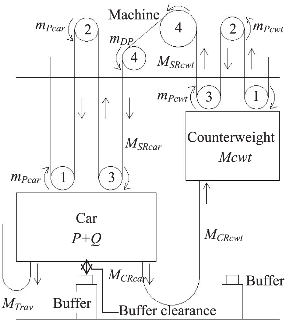
When an elevator car without an antirebound device descends from the lowest landing in response to abnormal situations, the counterweight will ascend when it is influenced by the pulling force of the suspension ropes. Therefore, the car descends, and the counterweight ascends with the influence of system acceleration until the car hits the buffer. After the car comes into contact with the buffer, the buffer’s reaction during the impact will cause the car to descend without system acceleration until the car comes to a complete stop. 9 A diagram that explains the dynamic motion of the elevator as the car descends is shown in Figure 1. The situation where the counterweight descends is similar to that of the car, and a diagram that explains the dynamic motion of the elevator when the counterweight descends is shown in Figure 2.
The car falls from its lowest landing.

The counterweight falls from its lowest landing.
From Figure 1, we can deduce the system acceleration of a car while it descends from the lowest landing, and the system acceleration acar equation is expressed as follows

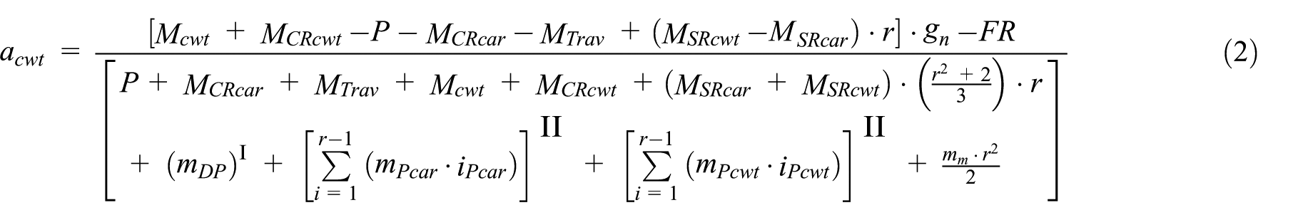
From Figure 2, we can deduce the system acceleration of a counterweight while it descends from the lowest landing, and the acceleration acwt equation is expressed as follows
Conditions:
I is for any deflection pulley on car or counterweigth side;
II is only for reeving ratio >1;
where a is the system acceleration; FR is the frictional force in the well; gn is the standard acceleration of free fall; H is the travel height; iPcar is the number of pulleys on car side with same rotation speed vpulley (without deflection pulleys); iPcwt is the number of pulleys on counterweight side with same rotation speed vpulley (without deflection pulleys); iPTD is the number of pulleys for tensioning device; mDP is the reduced mass (related to the car/counterweight) of deflection pulleys on car and/or counterweight side JDP · (vpulley/v)2/Rm2; mPcar is the reduced mass (related to the car) of pulleys on car side JPcar · (vpulley/v)2/Rm2; mPcwt is the reduced mass (related to the counterweight) of pulleys on counterweight side JPcwt · (vpulley/v)2/Rm2. MCR is the actual mass of compensation ropes/chains; MCRcar is the mass MCR on car side; MCRcwt is the mass MCR on counterweight side; Mcwt is the mass of counterweight including mass of pulleys; MSR is the actual mass of suspension ropes; MSRcar is the mass MSR on car side; MSRcwt is the mass MSR on counterweight side; MTrav is the actual mass of traveling cable; nC is the number of compensating ropes/chains; nS is the number of suspension ropes; nt is the number of traveling cables; mm is the mass of traction sheave; P is the masses of the empty car; Q is the rated load; r is the reeving factor; vpulley is the rotation speed of the pulley (rope speed).
Calculation of the impact speed of the counterweight
When the counterweight descends from the lowest landing of the elevator shaft, the car ascends; the dynamic model of this process is shown in Figure 3.

The counterweight’s downward motion.
It is observed from Figure 3 that the length of suspension cable and the length of compensation chain on the balance weight side decrease x, while the length of suspension cable, compensation chain length, and the length of moving cable on the car side increase x when the drop distance of balance weight is reduced x. Thus:
The equation representing the relationships among MSRcwt (the actual mass of the suspension ropes on the counterweight side), MSRcar (the actual mass of the suspension ropes on the car side), and x (the descending distance of the counterweight) is expressed as follows

The equation representing the relationships among MCRcwt (the actual mass of the compensation chains on the counterweight side), MCRcar (the actual mass of the compensation chains on the car side), and x (the descending distance of the counterweight) is expressed as follows

The equation representing the relationship between MTrav (the actual mass of the traveling cables) and x (the descending distance of the counterweight) is expressed as follows

where the variables are defined as follows: x is the descending distance of the counterweight, which is measured from the lowest landing; R is the travel height (the ascent) of the elevator; LSRcwt is the initial length of the suspension ropes on the counterweight side when the car is at the lowest landing; LCRcwt is the initial length of the compensating chain on the counterweight side when the counterweight is at the lowest landing; qS is the weight of suspension ropes per meter; qC is the weight of compensating chains per meter; LSRcar is the initial length of the suspension ropes on the car side when the counterweight is at the lowest landing; LCRcar is the initial length of the compensating chain on the car side when the car is at the lowest landing; LTrav is the initial length of the traveling cable on the car side when the car is at the lowest landing; qt is the weight of the traveling cables per meter.
From equations (3) to (5), it can be concluded that the actual masses of the suspension ropes, compensation chains, and traveling cables are subject to changes during the counterweight descent, which indicates that the system acceleration parameter is also variable. By substituting equations (3)–(5) into equation (2), the specific equation to calculate the acceleration can be obtained as follows

where a1, b1, c1, and d1 in the above equation are expressed as follows

The differential equation between v (the speed of the counterweight) and acwt (the acceleration) are as follows

By simultaneously integrating equation (8) on both sides, the following expression is obtained

According to equation (9), which operates under the assumption of zero speed at the initial position, the following equation about the relationship between the speed of the counterweight and the descending distance of the counterweight is derived

Calculation of the impact speed of the car
The dynamic model of the car during descent is shown in Figure 1. Because the theories on the buffer impact speed for both the car and counterweight are similar, the equation representing the relationship between the acceleration and descent of a car can be expressed as follows

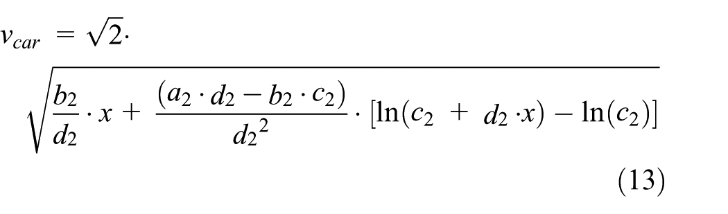
where a2, b2, c2, and d2 in the above equation are expressed as follows

The derivation process for the equation about the speed and descending distance of the car is similar to those of equations (8) and (9), and the equation is expressed as follows
Evaluation of the impact speed of the counterweight
Because the mass of the car and the travel heights of each elevator are different from each other during the actual production processes of elevators, all these factors should be taken into account to accurately analyze the influence of these parameters on the impact speed. Equation (6) is a relational expression that includes V (the speed of the counterweight), P (the mass of the car), and R (the travel height) for the case where the counterweight hits the buffer.
Take a 3000 kg freight elevator as an example, the speed of the counterweight will first be calculated in the case where the counterweight hits the buffer, wherein the mass of the car is within the range of 0–6000 kg and the travel height is within the range of 0–120 m. Moreover, the speed under different buffer spacing (descent distances) are shown in Figure 4.

Diagram of the speed of the counterweight upon hitting the buffer under different buffer clearances Scwt: (a) Scwt = 400 mm, (b) Scwt = 350 mm, (c) Scwt = 200 mm, (d) Scwt = 150 mm.
Figure 4 shows that the speed of the counterweight upon hitting the buffer varies obviously under different buffer clearances, and the counterweight speed will increase obviously along with the increase in buffer clearance; moreover, the speed of the counterweight upon hitting the buffer is significantly influenced by different travel heights and the car mass.
From Figure 4, we are unable to distinguish whether the car mass or travel height has a greater influence on acceleration. Therefore, a relational expression of the acceleration of counterweight is established as acwt(P, R), where P refers to the car mass and R refers to the travel height. In the case where the counterweight hits the buffer, the equation is shown as equation (14)
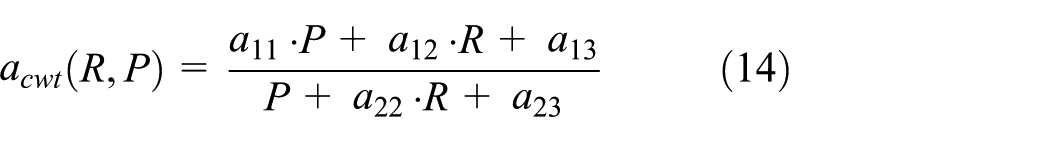
where a11, a12, a13, a22, and a23 in the above equation are shown as follows

Equation (14) can be used to determine the partial derivatives for P and R

By substituting the parameters of the abovementioned elevator into equation (16), we can obtain the increment relation between the acceleration and either P or R.
The following is observed from Figure 5:
The car mass has a greater influence on acceleration than the travel height.
The impact speed reduces along with the increase in the car mass and travel height.

Increment relation (a) between the acceleration and car mass and (b) between the acceleration and travel height.
Analysis of the calculation of the gravity stopping distance
When the counterweight fully compresses its buffer, the equation to calculate half of the gravity stopping distance of the car is expressed as follows
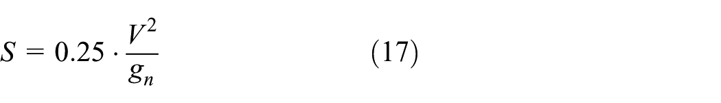
where V is the rated speed of the elevator.
From the abovementioned analysis, it can be concluded that there is a possibility that the impact speed of the car or counterweight may exceed 115% of the rated speed, but the impact speed will not exceed the tripping speed of the speed governor, which is employed to limit the maximum speed of the elevator when the counterweight or car impacts the buffer at a high speed. Moreover, various speed governor tripping speeds can be applied according to EN 81-20:2014: 0.8, 1.0, and 1.5 m/s. Therefore, 115% of the rated speed and these various tripping speeds are substituted into equation (17) to determine the gravity stopping distance under different speeds, and the results are shown in Table 1.
Half of the gravity stopping distance at different speeds.

The symbol “–” denotes that at this speed, the elevator cannot choose this tripping speed of the speed governor.
Table 1 shows that the gravity stopping distances under various speeds differ from each other. In the case where the guided travel satisfies the relevant standard exactly or the allowance is small, there will be a safety risk in terms of equipment damage or personal injury when counterweight hits the buffer if the speed of car exceeds 115% of the rated speed.
Test verification
To realize an accurate verification analysis, the authors carried out a test on the speed of the car of an example elevator in the test tower of Zhejiang Xizi Heavy Industry Machinery Co., Ltd., where the counterweight hits the buffer under different buffer clearances. The specifications of the example elevator are listed hereafter.
As the rated speed of the example elevator is 0.5 m/s, a variety of buffers can be selected for the test. Due to various demands, the parameters of a common buffer suitable for the example elevator are shown in Table 2.
Common buffer parameters.

The impact speed tests under different buffer clearances of 250, 350, and 400 mm are carried out, and the test results are shown in Figures 6–8, respectively.

Diagram of the (a) test acceleration and (b) test speed when the counterweight hits the buffer in the case where Scwt = 250 mm.
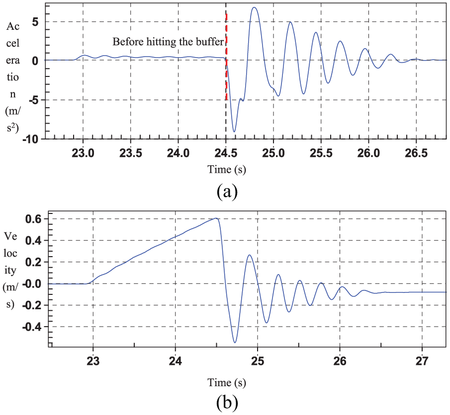
Diagram of the (a) test acceleration and (b) test speed when the counterweight hits the buffer in case where Scwt = 350 mm.

Diagram of the (a) test acceleration and (b) test speed when the counterweight hits the buffer in case where Scwt = 400 mm.
Figures 6–8 show that the acceleration of the car tends to be linear before hitting the buffer. However, after hitting the buffer, the velocity oscillates. In the test process, the maximum speeds of the car under the three different buffer clearances when the counterweight hits the buffer are shown in Table 3.
Maximum test speed of the counterweight when it hits the buffer under different buffer clearances.

From the test results, we can work out that the impact speed increases along with the increase in the buffer clearance, which can be summarized as follows:
When the buffer clearance is 250 mm, the impact speed is less than or equal to 115% of the rated speed of the elevator.
When the buffer clearance is 350 mm, the impact speed is 122% of the rated speed of the elevator.
When the buffer clearance is 400 mm, the impact speed is 146% of the rated speed of the elevator.
Although the buffer clearance can satisfy the old Chinese standard mentioned above, GB10050-1993, it is highly probable that the impact speed will exceed 115% of the rated speed of the elevator in reality. If the rated speed of the elevator is smaller than that of the example elevator, the ratio between the impact speed and rated speed will be much larger. When applying the design in Table 3, whose impact speed exceeds 115% of the rated speed of elevator, the following conclusions can be drawn:
If the selection of buffer type is improper, for example, this example elevator adopts the HYF65 hydraulic buffer shown in Table 2, the maximum permitted speed of the buffer cannot meet the requirements under the counterweight buffer clearance of 400 mm. Then, this improper buffer selection will reduce the service life of buffer, cause damage to the buffer, and lead to safety risks such as equipment damage and personal injury.
In case that the maximum permitted speed of buffer is not violated, if the relevant parameters are calculated according to 115% of the rated speed specified in the standard, then the guided travel of the elevator will be insufficient to ensure the safety of the elevator in case of accidents, 10 such as the guide shoe of the elevator car running off the guide rail, equipment damage, and personal injury.
In actual tests, the impact speed may be reduced by some factors such as the inertia of the rope sheave, friction force of the well, and loss of efficiency; therefore, the actual impact speed test data obtained will have lower values than the theoretical data. Nevertheless, there still exist safety risks caused by failing to comply with operating requirements.
Improvement suggestions
Calculation of the maximum buffer clearance
According to the results shown in Figures 6–8, if the buffer clearance parameter is not taken into consideration, then the selected buffer and the guided travel calculation cannot always meet the requirements in actual use and potential safety hazards may occur.
For the case of buffer selections, the authors hold the view that the parameters that should be taken into consideration include not only the counterweight (or car) mass and rated elevator speed but also the speed of the car (or counterweight) when hitting the buffer. Moreover, the authors believe that the Sbuf_cwt (buffer clearance of the counterweight) and Sbuf_car (buffer clearance of the car) must be adjusted according to equations (18) and (19) below to meet the requirements in actual use.
Using equation (10), the equation representing the relationship between the permitted speed of the buffer on the counterweight side and the buffer clearance of the counterweight can be obtained in the following form

where Vbuf_cwt is the permitted speed of the buffer on the counterweight side.
Through equation (13), the relationship equation between the permitted speed of buffer on the car side and the buffer clearance of the car can be obtained
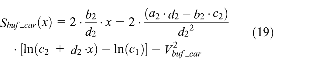
where Vbuf_car is the permitted speed of the buffer on the car side.
The approximate solution of the above equation can be obtained by employing the Newton–Raphson method

For the descent of the counterweight, the maximum value of x can be calculated as follows

For the descent of the car, the maximum value of x can be calculated as follows

Equations (21) and (22) are iterated until the difference value of 0.1 mm is obtained, and the equation is shown as follows

Calculation of the maximum guided travel
When calculating the guided travel of the elevator on the basis of the above analysis, the authors think that when the impacting speed exceeds 115% of the rated speed of elevator, the following conclusions can be drawn:
If the impacting speed does not exceed the tripping speed of the overspeed governor, half of the gravity stopping distance shall be calculated according to the speed of hitting the buffer, and equation (10) or (13) can be referenced for details.
If the impact speed exceeds the tripping speed of the overspeed governor, half of the gravity stopping distance shall be calculated according to the tripping speed of the overspeed governor.
Each elevator has its own car and travel height variety, and thus, we should take into account the most extreme case when calculating the impact speed.
Conclusion
This article first establishes a theoretical model to calculate the impact speeds of the car and counterweight and then performs simulated calculations for the model. Subsequently, testing verification is conducted for the example elevator used in this article, and the test results are consistent with the theoretical analysis. Through analysis, the authors draw the conclusion that the buffer clearance of the elevator has a substantial influence on the buffer selection and the guided travel calculation. Therefore, the authors propose some suggestions for improvement and models for correlation calculations to provide references for peers. In future works, the authors will submit suggestions to the China Elevator Association in the hope of revising the elevator standards to make elevators safer.
Footnotes
Handling Editor: Vesna Spasojević Brkić
Declaration of conflicting interests
The author(s) declared no potential conflicts of interest with respect to the research, authorship, and/or publication of this article.
Funding
The author(s) disclosed receipt of the following financial support for the research, authorship, and/or publication of this article: This work was supported in part by Key Technological Innovation Projects in Zhejiang Province ([2018]275)