
Abstract
The surface material of marine ship hulls suffers degradation by slurry erosion because of the impact of sands or solid particles in seawater. When the ship’s moving speed increases, pressure is changed suddenly and cavitation erosion will occur. Therefore, in the ocean, the corrosion of the surface material of the ship hulls is a combined damage in a slurry erosion and cavitation erosion states. An experimental device, for the combined wear, capable of simulating the above working conditions is designed and manufactured. A combined wear test of various materials (Q235, DH32, and NM360 steels) is conducted. The results show that cutting furrows of the slurry erosion, pinholes of the cavitation erosion, holes of electrochemical corrosion, and their combined effect increase the material wear rates and areas. Ductile materials of high strength have less slurry and cavitation damage, and more corrosion damage. For ductile materials of low strength, slurry and cavitation wear play an important role. When the slurry impact speed is increased, the wear degree of materials is also increased. This experimental setup for the combined wear provides a strong support for the development of wear-resistant materials for ship hulls and the structural optimization of ship hulls.
Keywords
Introduction
The main destruction forms of the surface material of marine ship hulls are corrosion, slurry erosion, and cavitation erosion. When ships travel in the ocean, the surface of the hull is damaged by slurry erosion. With further increase in the speed of ships, cavitation erosion is also caused because of the pressure difference. At the same time, there is always the seawater corrosion of the surface of ship hulls.
Slurry erosion is a type of wear caused by the impact of sands on a metal surface. The test types for slurry erosion include the rotator, 1 jet,2,3 and pipeline.4,5 Cavitation erosion is the phenomenon of cave-like exfoliation occurring on a metal surface. When the surrounding high-speed fluid has drastic pressure changes, bubbles will form and collapse. The test types for cavitation erosion are the vibrational,6–8 Venturi,9,10 and rotatory disk. 11 Moreover, electrochemical corrosion is the destruction caused by an electrochemical reaction between the metal surface and the surrounding electrolyte solution. A three-electrode system is usually used to study electrochemical corrosion in different environments.12,13 Slurry erosion and cavitation erosion both belong to abrasion. The wear loss of abrasion is proportional to the normal applied load and inversely proportional to the surface hardness of material. The wear resistance of the material depends upon the toughness of material which reduces with increase in the hardness. The abrasive surface morphology of material includes plastic deformation, grooves, ridges and craters, and the material removal by plowing. The electrochemical corrosion test generally uses potentiodynamic polarization method or electrochemical impedance spectroscopy method to test the corrosion resistance of materials. The related electrochemical parameters include corrosion potential, corrosion current density, corrosion rate, protection efficiency, and so on. 14
Scholars have studied the factors affecting slurry erosion, cavitation erosion, and corrosion, and analyzed the wear mechanism and the tribological characteristics of different materials under different wear forms. The damage degree of slurry erosion is related to many factors, such as impact speed, impact angle, particle size, and particle concentration.15,16 The factors affecting the damage degree of the cavitation erosion are the sizes and numbers of cavitation holes. 17 The micro-cutting material removal mechanism of erosion wear was dominant for acute impact angles that show shallow deep and long craters. At normal impact angle, the material was displaced by plastic deformation around the rounded indentation craters and forms a rim. 18 The main effects of the erosion-corrosion wear of API 5L X65 carbon steel are velocity, oxygen concentration, interaction between particle concentration and concentration of copper ions, temperature, and interaction between velocity and concentration of dissolved oxygen. The primary damage mechanisms are the deposition of corrosion products consecutively disturbed by impinging particles and localized plastic deformation. 19 In the combined wear of slurry erosion and corrosion, the main failure mode of the ductile materials is sandy water erosion, and the main failure mode of the ductile material of larger hardness is cavitation erosion. 20 To change the slurry erosion-corrosion resistance of metal materials, many approaches have been used. For example, ZrO2 particles 14 or NbC particles 21 can be added to stainless steel, volume fraction of Mo2NiB2 phase 22 can be increased in cermet, or WC-10Co-4Cr cermet coating 23 was deposited on the stainless steel.
The experimental setup for the combined wear of slurry erosion and cavitation erosion is a rotatory disk-type device. 24 The experimental setup for the combined wear of slurry erosion and electrochemical corrosion is mainly a rotatory three-electrode system25,26 or a jet-type three-electrode system. 27 The vibrational three-electrode system28–30 is for the test of the combined wear for cavitation erosion and the electrochemical corrosion. However, the experimental setup for the combined wear of slurry erosion, cavitation erosion, and electrochemical corrosion is temporarily less introduced. So, this combined experimental setup for slurry erosion, cavitation erosion, and electrochemical corrosion is an essential tool to study new wear-resistant materials and the structural optimization of ship hulls.
According to the comprehensive analysis of the above literature, an experimental device for electrochemical corrosion uses a three-electrode system that the electrochemical parameters are adjusted. Among three main experimental devices for slurry erosion, the jet device can realize the accurate control of impact speed, impact angle, solid particle size and concentration, and other parameters. The rotatory device can realize the accurate control of rotational speed, and it can simulate the actual working conditions of turbine blades, pump impellers, and so on. But it is difficult to control the uniform distribution of sand and quantify the effect of sand on the material. The pipeline device has relatively high cost, large space, and long test period. Compared with the rotatory device, it is suitable for simulating the actual pipeline erosion. Among three main experimental devices for cavitation erosion, the vibrational device cannot realize impact action. The rotatory device is suitable for simulating cavitation erosion of rotating fluid machinery. The Venturi device is used to simulate the cavitation erosion of pipelines with varying diameters.
In the ocean, the slurry erosion of the ship hull surface approximates the damage of the specimen surface caused by high-speed slurry impact. According to the above analysis of experimental setups, a jet experimental setup for the combined wear of slurry erosion, cavitation erosion, and electrochemical corrosion is developed for simulating the destruction of the ship hull surface in the ocean. The experimental setup has two specimen zones. Because of the gap between the two zones, it is easy to produce fluid pressure difference, resulting in cavitation erosion. It is equipped with the stirring device for fully mixing artificial seawater (i.e. sandy and saline water), and there exists corrosion. The slurry pump and reducing pipe are used to pressurize and accelerate the artificial seawater, and there will be slurry erosion. Besides, the impact speed, impact angle, sand size, sand concentration, and environmental pressure are accurately adjusted. Furthermore, it can complete the combined wear tests for many specimens with and without the application of electrochemical corrosion in the same environment at one test.
Experimental setup for the combined wear
Experimental setup and its composition
Figure 1 is the designed and manufactured experimental setup for the combined wear of slurry erosion, cavitation erosion, and electrochemical corrosion. Its overall dimension is 4 m × 1.5 m × 2.6 m. It includes a slurry pump, a stirring tank, a blender, an electrochemical workstation, an erosion and corrosion chamber, pressure and flow sensors, and so on.
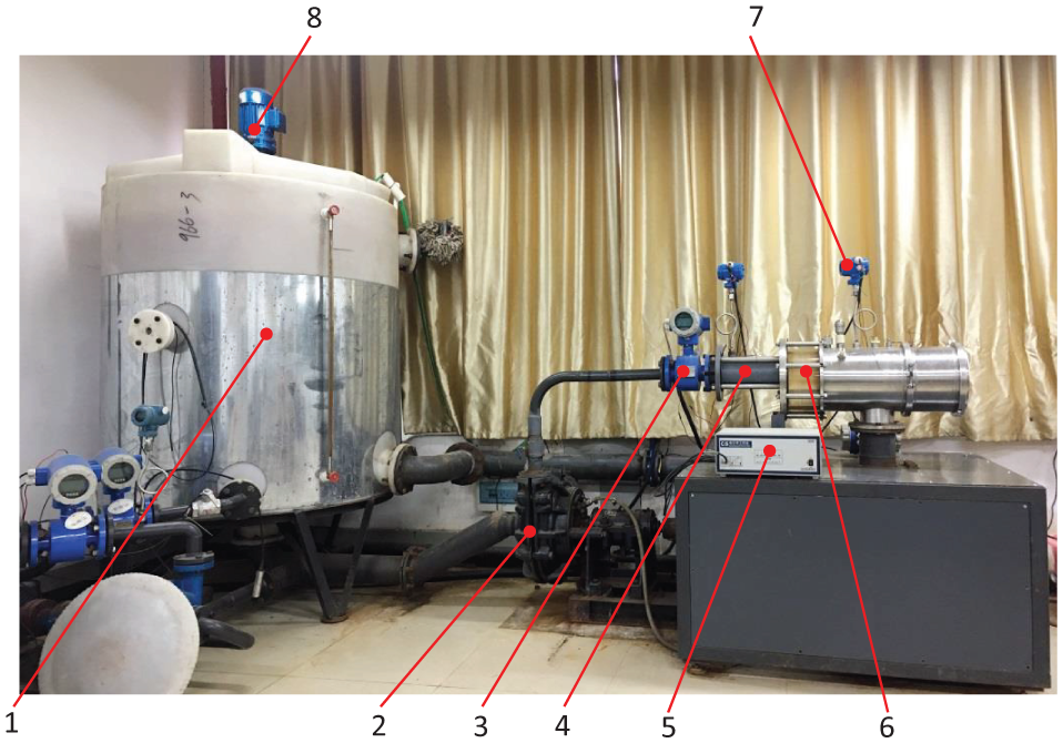
Experimental setup for the combined wear of slurry erosion, cavitation erosion, and electrochemical corrosion.
The artificial seawater in the tank is stirred and sucked into the slurry pump from the bottom of the tank. The fluid is pressurized by the pump and speeded up through the reducing pipe to form a parallel jet at the zone 1. The fluid reaches the zone 2 to form a submerged jet in the erosion and corrosion chamber. The chamber is equipped with reference electrodes, auxiliary electrodes, and working electrodes. The specimens at the two zones are used as working electrodes and produce the combined wear of slurry erosion, cavitation erosion, and corrosion. The fluid flows out from the outlet of the chamber and back to the tank through the throttle valve. The environment pressure of the chamber is changed by the throttle valve. Stainless steel is used for the material of the pipe through which the slurry flows in the test system.
Erosion and corrosion chamber
The erosion and corrosion chamber is a key component of the experimental setup for the combined wear. In the chamber, the specimens suffer the combined wear of slurry erosion, cavitation erosion, and corrosion.
Considering many factors, the slurry pump and reducing pipe are used to pressurize and accelerate. Because the sudden pressure change is required to produce cavitation, two specimen wear zones are designed in the erosion and corrosion chamber. As shown in Figures 2 and 3, the first specimen zone is the parallel jet zone 1 (i.e. the narrow channel surrounded by the four inner walls of the nozzle). The specimen holder at the zone 1 can be disassembled into parts, and it is bolted to the slurry erosion and corrosion chamber. The average impact speed of the slurry at the zone 1 can be calculated by measuring the average flux rate of the slurry over a period of operation time.

Specimen zones in the erosion and corrosion chamber.
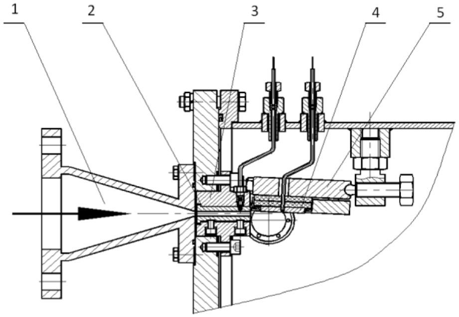
Local enlarged drawing of the erosion and corrosion chamber.
The second specimen zone is the angle jet zone 2, and the specimens suffer a submerged jet. The specimen holder at the zone 2 is connected with the chamber by one spherical end of the bolt, and the other end of the bolt is angularly adjusted by a support body. Because the specimen position at the zone 2 is changeable, it can be used to study the impact angle and other parameters. The specimen holder at the zone 2 can also be disassembled. As there is gap between the zones 1 and 2, it is easier to produce fluid pressure difference, resulting in cavitation erosion.
The numerical analysis shows that the greater the taper of the reducing pipe is, the greater the pressure loss is, the higher the motor power of the pump is, and the lower the efficiency of the experimental setup is. The smaller the taper of the reducing pipe is, the longer the pipe length is, the greater the frictional head loss is, and the more difficult the manufacturing of the pipe is. Combining these factors, the taper of the reducing pipe is taken as 15°.
Specimens and specimen holders
In one test, eight specimens are installed on the specimen holders of the zones 1 and 2 (see Figure 4). The dimension of the specimen zone 1 (i.e. the narrow channel surrounded by the four inner walls of the nozzle) is 24 mm × 5 mm × 50 mm. Six specimens are installed at the parallel jet zone 1. Two specimens are installed at the angle jet zone 3. The gap between the specimens and their holders or specimens is filled with the plastic of 0.3 mm for insulating and supporting materials. There are sealing devices between every electrochemical electrodes and the wall of the erosion and corrosion chamber. The nozzle material is made of cemented carbide.
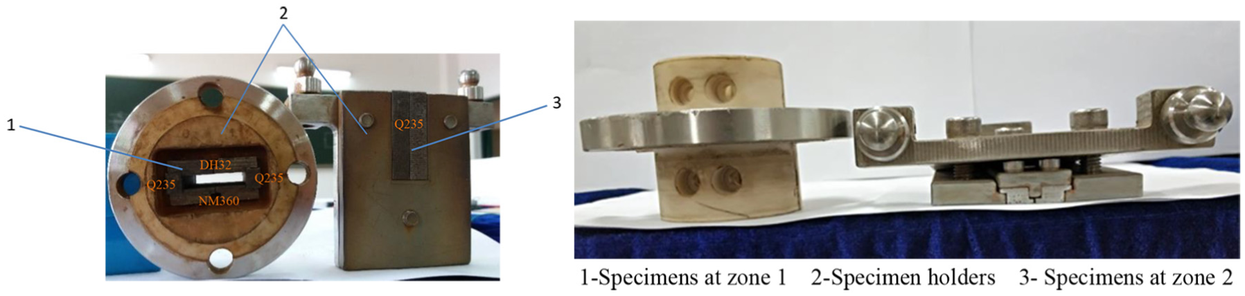
Specimen holders and specimens at zones 1 and 2.
Test parameters of the combined wear test
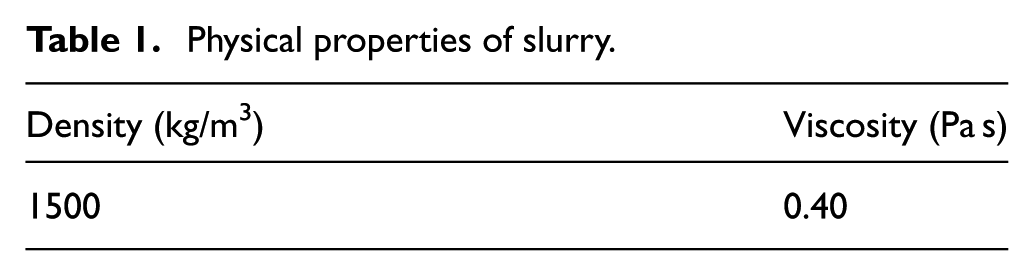
The artificial seawater is made of water, sand, and sea salt that are well stirred in the stirring tank. Because the large amount of fresh water in the inland rivers is injected into the Bohai Sea of our country, the salt content is relatively low. Based on the actual seawater in a certain area of the Bohai Sea, the sand concentration (kilograms of sand per cubic meter of water) is 1.1 kg/m3 (i.e. 0.11 wt%), the size of sand particles is less than 0.315 mm in diameter, and the salt concentration (kilograms of salt per cubic meter of water) is 1.67 kg/m3 (i.e. 0.167 wt%) in the test. The physical properties of slurry are show in Table 1.
Physical properties of slurry.
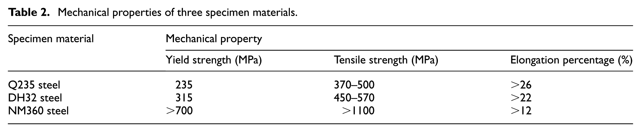
The materials of the test specimens are selected from Q235 steel, DH32 steel, and NM360 steel. Their mechanical properties are shown in Table 2. Q235 steel is a kind of ordinary carbon structural steel, and it is mainly used to make steel bars, bridges, vehicles, boilers, containers, and ships. DH32 steel is a high-strength low-temperature structural steel that is mainly used to make ship plates. NM360 steel is a kind of high-strength wear-resistant steel that is widely used in mining machinery, coal mining machinery, environmental protection machinery, engineering machinery, and so on.
Mechanical properties of three specimen materials.
Different material specimens are shown in Figure 5. Among six specimens at the zone 1, two Q235 steel specimens (53 mm × 8 mm × 5 mm) are installed at the side walls, two DH32 steel specimens (53 mm × 17 mm × 5 mm) are installed at the top wall, and two NM360 steel specimens (53 mm × 17 mm × 5 mm) are installed at the bottom wall. Two Q235 steel specimens (49 mm × 12 mm × 5 mm) are installed at the zone 2. For each of two specimens of each material at the zones 1 and 2, one specimen is applied with the polarization potential of electrochemical corrosion, and the other specimen is not applied with the polarization potential (i.e. in the natural corrosion state). Each test time is 24 h. The eight specimens are unloaded, cleaned, dried, weighed, and photographed after every 4 h.

Different material specimens before test: (a) Q235 steel at zone 1, (b) DH32 steel at zone 1, (c) NM360 steel at zone 1, and (d) Q235 steel at zone 2.
In the test, the electrochemical corrosion of the test specimens was generated by an electrochemical workstation of the model CS300. The working electrode end of the electrochemical workstation is connected to the wires drawn from the test specimens, the auxiliary electrode end is connected to the graphite rod that is drawn from the corrosion chamber, and the reference electrode is connected to the solid Ag–AgCl electrode that is drawn from the corrosion chamber. For the electrochemical workstation, the polarization potential of the working electrode is set to 0.2 V, that is, when electrochemical corrosion occurs, the potential value of the working electrode relative to the reference electrode is equal to 0.2 V plus the potential value of the working electrode in the natural corrosion state. The polarization time is the entire test time.
In the test, the rotational speed of the slurry pump motor can be changed by adjusting the frequency of the installed frequency converter, and the impact speed at the specimen zone 1 is calculated by the installed electromagnetic flowmeter. The slurry impact speed (vi) at the specimen zone 1 is adjusted to about 20 or 22.5 m/s, and the flow of the slurry is turbulent. The operating parameters of the test are shown in Table 3.
Operating parameters of the test.

Results and discussion
Figures 6 and 7 show all the specimens in natural and electrochemical corrosion states after 24-h test. The wear degrees of different material specimens are different. Regardless of whether the electrochemical corrosion voltage is applied or not, each specimen has the marks of the combined wear of slurry erosion, cavitation erosion, and corrosion. The corrosion marks of the DH32 and NM360 steel specimens are more obvious.
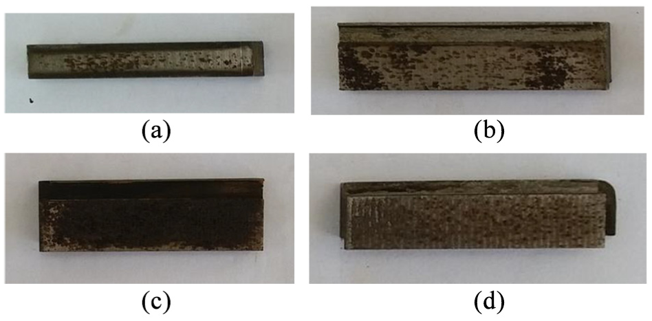
Different material specimens in natural corrosion state after 24-h test: (a) Q235 steel at zone 1, (b) DH32 steel at zone 1, (c) NM360 steel at zone 1, and (d) Q235 steel at zone 2.
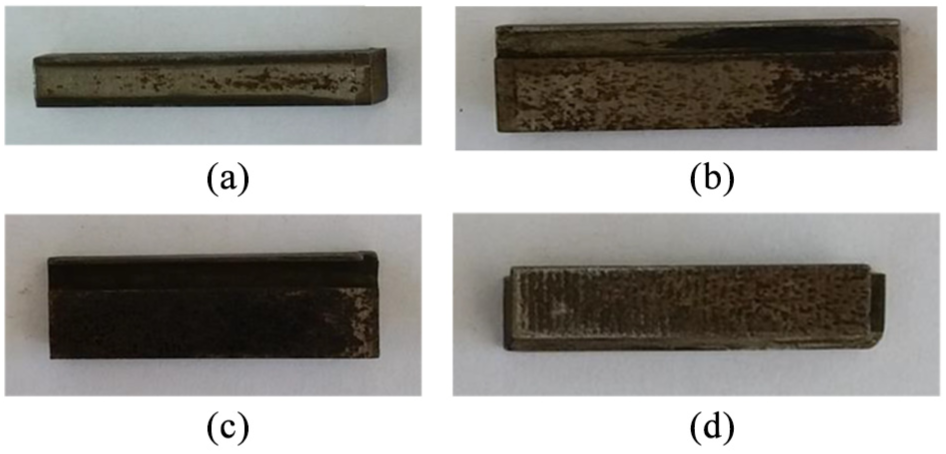
Different material specimens in electrochemical corrosion state after 24-h test: (a) Q235 steel at zone 1, (b) DH32 steel at zone 1, (c) NM360 steel at zone 1, and (d) Q235 steel at zone 2.
For uniform comparison, the cumulative mass loss of the specimen (M) is defined as the lost milligrams per cm2 wear area of the specimen with time.
Figures 8–11 show the cumulative mass loss curves of different material specimens at two zones for the combined wear with and without the application of electrochemical corrosion when the slurry impact speed at the specimen zone 1 is 20 or 22.5 m/s. When time increases, the cumulative mass losses of all specimens are increased linearly in a different degree. When the slurry impact speed is increased, the cumulative mass losses of all specimens are also increased accordingly, and the degree of wear is aggravated. When the polarization potential is applied, the cumulative mass losses of the same material specimens at the same zone are greater than those in natural corrosion state. For Q235 steel, the cumulative mass losses of the specimens at the zone 1 are greater than those at the zone 2. This is because the slurry impact speed and the degree of cavitation at the zone 2 are greater than those at the zone 1, which agrees with the numerical results.

Cumulative mass loss curves of Q235 steel at zone 1 in natural and electrochemical corrosion state.

Cumulative mass loss curves of DH32 steel at zone 1 in natural and electrochemical corrosion state.

Cumulative mass loss curves of NM360 steel at zone 1 in natural and electrochemical corrosion state.

Cumulative mass loss curves of Q235 steel at zone 2 in natural and electrochemical corrosion state.
Using the same computational fluid dynamics (CFD) method as in Aguirre and Walczak, 19 the numerical calculation on the interactive wear of slurry erosion and cavitation erosion is performed. Figure 12 shows the slurry impact speed at the specimen zones 1 and 2. The maximum impact speed at a cross section of the zone 1 is 24.9 m/s, and at the front cross section of the zone 2 is 29.1 m/s. The average impact speed at the zone 1 is 20.7 m/s, which is close to the experimental data.

Slurry impact speed at specimen zones under slurry erosion and cavitation erosion: (a) specimen zone 1 and (b) specimen zone 2.
Figures 13 and 14 show the cumulative mass loss curves of all specimens at the zone 1 under the slurry impact speeds (vi) of 20 and 22.5 m/s. At the same slurry impact speed, in the electrochemical corrosion state, the comparison of all cumulative mass losses is W1Q235e < W1DH32e < W1NM360e. In the natural corrosion state, the comparison is W1Q235n < W1DH32n < W1NM360n. The results show that regardless of whether the electrochemical corrosion is applied or not at the specimen zone 1, the wear degrees of the three ductile materials (i.e. the material elongation is greater than 5%) of different strengths are different. The mass losses of the ductile materials of high strength (DH32 steel and NM360 steel) are greater than those of the ductile material of low strength (Q235). The mass losses of three ductile materials are increased with the increase in the test time in 0–4 h. After 4 h, the mass losses of Q235 steel are increased slowly, while those of DH32 steel and NM360 steel are increased rapidly. This indicates that the wear rate of ductile materials is basically the same in the initial stage under the combined wear of slurry erosion, cavitation erosion, and corrosion. With the increase in the working time, the wear rate of ductile materials with high strength (DH32 steel and NM360 steel) is higher than that of ductile materials with low strength (Q235 steel).

Cumulative mass loss curves of three material specimens at zone 1 (vi = 20 m/s).

Cumulative mass loss curves of three material specimens at zone 1 (vi = 22.5 m/s).
Figures 15 and 16 show the morphology pictures of the centers of the worn surfaces of the Q235 steel specimens at two zones in the natural and electrochemical corrosion state after 24-h test.

Morphologies of the center of the worn surface of the Q235 steel at zone 1 after 24 h: (a) natural corrosion (vi = 20 m/s), (b) electrochemical corrosion (vi = 20 m/s), (c) natural corrosion (vi = 22.5 m/s), and (d) electrochemical corrosion (vi = 22.5 m/s).

Morphologies of the center of the worn surface of the Q235 steel at zone 2 after 24 h: (a) natural corrosion (vi = 20 m/s), (b) electrochemical corrosion (vi = 20 m/s), (c) natural corrosion (vi = 22.5 m/s), and (d) electrochemical corrosion (vi = 22.5 m/s).
In artificial seawater, when the constant polarization potential is not applied, that is, in the natural corrosion state, the slurry impact causes furrows and microcracks on the surface of the specimens. Because of the existence of these furrows and microcracks, the local pressure of the fluid is different. The bubbles form in the low pressure area, and they collapse in the high pressure area. Bubble collapse produces cavitation pinholes on the material surface. Under the combined action of slurry erosion and cavitation erosion, the material surface layer loosens to result in material loss. Because natural corrosion is not obvious, the material damage is mainly caused by the combined wear of slurry erosion and cavitation erosion.
When the constant polarization potential is applied, more corrosion pits (pitting corrosion) are generated by electrochemical action and there is stress concentration, which will accelerate slurry erosion and cavitation erosion. At the same time, the two forms of wears generate erosion furrows and cavitation pinholes on the material surface, and they damage the protection film of the material surface, accelerating the electrochemical corrosion. Cutting furrows of the slurry erosion, pinholes of the cavitation erosion, pits of electrochemical corrosion, and their combined action increase the material wear rates and areas, and the material loss is serious. Figures 13 and 14 indicate that the combined effect of slurry erosion, cavitation erosion, and electrochemical corrosion is more serious at higher slurry impact speed.
Figures 17 and 18 show the morphology pictures of the centers of the worn surfaces of the DH32 and NM360 steel specimens at the zone 1 in the natural and electrochemical corrosion state after 24-h test. For the ductile materials (DH32 and NM360 steels) of high strength, their corrosion degrees are greater than those of the ductile material (Q235 steel) of low strength, but their slurry and cavitation wear degrees are smaller. For the ductile material (NM360 steel) of the highest strength, the degree of corrosion is the most serious.

Morphologies of the center of the worn surface of the DH32 steel at zone 1 after 24 h: (a) natural corrosion (vi = 20 m/s), (b) electrochemical corrosion (vi = 20 m/s), (c) natural corrosion (vi = 22.5 m/s), and (d) electrochemical corrosion (vi = 22.5 m/s).

Morphologies of the center of the worn surface of the NM360 steel at zone 1 after 24 h: (a) natural corrosion(vi = 20 m/s), (b) electrochemical corrosion (vi = 20 m/s), (c) natural corrosion (vi = 22.5 m/s), and (d) electrochemical corrosion (vi = 22.5 m/s).
By synthesizing the mass loss curves of Figures 13 and 14, the mechanism of combined wears of slurry erosion, cavitation erosion, and electrochemical corrosion is that the wear of ductile materials is a combination of slurry erosion furrows, cavitation pinholes, and corrosion holes. Because of the interaction of slurry erosion and cavitation erosion, the low-strength ductile materials are easy to lose, and the corrosion damage is not obvious; while the high-strength ductile materials suffer serious corrosion damage, combined with slurry erosion and cavitation erosion, the material loss is greater. The increase in the working time and impact speed will aggravate the damage of ductile materials.
Conclusion and future work
The designed and manufactured experimental setup for the combined wear can perform several specimen tests involving slurry erosion, cavitation erosion, electrochemical corrosion, and their combinations simulating the material damage of ship hulls in the ocean. It can be used as a quantitative research tool for new corrosion-resistant materials under slurry and cavitation wear conditions.
A combined wear test of various ductile materials (Q235, DH32, and NM360 steels) is conducted. For the combined wears of metal ductile materials, because of more serious corrosion damage, the material losses high-strength ductile materials are greater. For low-strength ductile materials, the material loss is mainly caused by the slurry erosion and cavitation erosion. The application of a constant potential on the specimens will exacerbate the corrosion of the material, and corrosion is more damage to materials than slurry and cavitation wear. When working time or slurry impact speed is increased, the wear degree and mass loss of materials are all increased.
The impact angle, sand size, sand concentration, environmental pressure, temperature, and other influencing factors for slurry erosion, cavitation erosion, corrosion, and their combined actions should be further researched.
The topography and roughness of materials also affect their wear and corrosion resistance, which we must study in the future.
Footnotes
Handling Editor: Noel Brunetiere
Declaration of conflicting interests
The author(s) declared no potential conflicts of interest with respect to the research, authorship, and/or publication of this article.
Funding
The author(s) disclosed receipt of the following financial support for the research, authorship, and/or publication of this article: This work was supported, in part, by the National Natural Science Foundation of China under grants 51475049 and 51875051, the Scientific Research Fund of the Hunan Provincial Education Department under grant 16A021, and the Changsha Municipal Science and Technology Project under grant k1705011.