
Abstract
This article presents a new approach aiming to reducing pump vibration by modifying its baseplate structure. The finite element models of the vertical pump were established and validated by the experimental impact test. The natural frequencies of pump were mapped in both experimental and numerical methods. The weak stiffness of the baseplate was identified as the root cause for the pump vibration. A topology optimization was used for enhancing the stiffness of baseplate and controlling its weight. The new baseplate was designed according to the inputs from optimization results and manufactured by the casting method. Both the vibration tests and the numerical simulations were carried out to investigate the vibration behaviors of the optimized pump model. The differences of vibration characteristics between original and optimized pumps were evaluated using 1/3 octave-band filter technique. Results show that the vibration was suppressed, and the resonance at 31.5 Hz was eliminated using the optimized baseplate. In particular, the maximum vibration amplitude of the vertical pump was reduced from 4.05 to 1.75 mm/s at the low flow rate condition. It was experimentally confirmed that the vibration amplitude of the optimized model complies with the requirements of the International Organization for Standardization standard and ensures the pump can operate stable for a long time.
Introduction
The vertical pumps are widely applied for heating, ventilation, and air-condition (HVAC) system; water supply system; and ship system. As a rotating body, it is capable of vibration. Thus, its design generally requires consideration of its oscillatory behavior. In order to solve vibration problems of pump, it is often vital to attempt to understand the interaction of mechanical and hydraulic phenomena. The main mechanical inducers for pump vibration were summarized as rotor unbalance, misalignment of coupling or bearing, bent shaft, bad anti-friction bearing, mechanical looseness, poor foundation, and soft baseplate. 1 The vortex, rotor–stator interaction, rotating stall, and cavitation are the main hydraulic causes for pump vibration.2–6 Basically, the forced vibration is one of the typical vibration modes that was distinguished in a pump. It is generated if a system consisting of mass, spring, and damping is excited by a periodic force. In this way, an unbalance excites rotor vibration, which is transmitted by the bearings, the casing, and the baseplate to the foundation. The resonance occurs when the exciting frequency coincides with the natural frequency, and the vibration amplitude can become very high if damping is low. This strong vibration can reduce the lifetime of pump and even damage the pump. Therefore, it is vital to understand the pump vibration behaviors and reduce its vibration level.
Recently, many studies have been concentrated on the vibration suppressions of the rotating machinery. Active bearings were applied to eliminate the unbalance and resonance of rotor systems.7–9 Also, some special absorbers or dampers were designed for vibration reduction in rotor systems.10–13 As we know, no matter the active bearing and the special absorber, they are the external supplement devices used to reduce the vibration level of system. However, from design point of view, it is more effective to optimize the structural or hydraulic components of rotating systems to suppress to vibration energy. Dong and Chu14–16 presented that both the increase in the gap between tongue and impeller, and the enhancement of stiffness of tongue can reduce the vibration of centrifugal pump. Spence and Amaral-Teixeira 17 investigated the effects of different impeller arrangements on pressure pulsations of pump, and a reasonable impeller arrangement that can increase component life and reduce vibration through reductions in pressure pulsations was proposed. Scheit et al. 18 presented that by varying the blade wrap angle, the sound and vibration levels of centrifugal impeller can be reduced. Khalifa et al.19,20 demonstrated that the pump vibration has tight correlation with the internal pressure pulsations, and the use of V-cut at impeller blade outlet can effectively reduce the pressure pulsation and vibration of the pump.
Although much work has been done on vibration control of pump, there is sparse literature available to present the methods of improving the stability of centrifugal pump by optimizing its structure. In this study, a topology optimization is conducted to change the stiffness of structures for the purpose of reducing the vibration level of pump. There are a number of topology optimization methods addressed before, for instance, the homogenization method, 21 variable density method,22,23 and evolutionary structural optimization.24,25 It is well known that the lighter and quieter machines are obtained using the topology optimization methods in the automotive industry.26,27 Also, a housing structure of an axial piston pump was optimized for noise and vibration reduction using the topology design method, consequently, the average sound pressure level was reduced by about 2 dB(A). 28
The objectives of this research are as follows: (1) find the root causes of vibration for a vertical pump, (2) build a finite element model of the vertical pump for the modal analysis, (3) use the topology optimization method to modify the structure of baseplate for the purpose of increasing the stiffness of pump unit and reducing the vibration level, and (4) evaluate the differences of vibration characteristics between original and optimized pumps using the experimental measurements and 1/3 octave-band filter technique.
Pump model and test arrangement
A vertical pump configuration
A vertical pump studied in the article is schematically shown in Figure 1. Basically, the pump was constructed with an impeller, pump casing, motor, shaft, cover, motor stool, shaft seal, wear ring, and baseplate. The main operating and geometrical parameters are illustrated in Table 1.

Pump configuration.
Main data of the vertical pump.

Experimental facility
The pump was driven directly by a Siemens motor. The parameters of motor are 5.5 kW, 60 Hz, and 4-pole. Speed was controlled by Danfoss frequency converter and the rated speed during the test is 1770 r/min. To eliminate the influence of cavitation on the vibration characteristics of the pump, the inlet pressure during the test was guaranteed to be 0.2 MPa. Figure 2 shows the vibration test facilities for the vertical pump. It is a closed-loop system and its maximum pressure is 1.6 MPa. To ensure a stable water flow in the pump inlet, the system was designed with two large water tanks. The cavitation tank was equipped with a flow straightener for stabilizing the water flow. The system also included a 3-ton vibration isolation concrete foundation. To minimize the influence of the external vibrating sources on the vibration characteristics of the testing pump, the pump was fixed on the vibration isolation concrete foundation through four mounting holes, and the rubber flexible joints were applied to connect the pump and the external pipelines. Meanwhile, the external pipelines were fixed to the ground through the rigid fixtures to eliminate the vibration transferring from the external pipelines to the test pump. It is because this external vibrating energy can affect the test accuracy.

Vibration test facility for a vertical pump.
In addition, the piezoelectric vibration acceleration sensors and the signal acquisition and analysis system from Danish B&K Company were used to measure the vibration signals. According to the requirements of ISO 10816, 19 vibration acceleration monitoring points were arranged in the vibration-sensitive area of the pump unit to obtain sufficient vibration information. The pump unit was divided into four regions. First one is the motor region and its corresponding sensors are nos 1, 2, 3, 4, and 5; second one is the pump region and its corresponding sensors are nos 6, 7, 8, 9, 10, 11, 12, and 13; third one is the baseplate region and its corresponding sensors are nos 14 and 15; forth one is pipeline region and its corresponding sensors are nos 16, 17, 18, and 19. The vibration monitoring points are presented in Figure 3. In Figure 3, the square and circle represent different views of sensor, the circle is the front view of sensor, and the square is the side view of sensor. To ensure the experimental results with a high accuracy, the following maximum uncertainties were established for the measured magnitudes: (1) static pressure: ±1.5%; (2) flow rate: ±3%; (3) rotational speed: ±0.5%; (4) shaft power: ±3%; and (5) vibration acceleration magnitude: ±2%.

Arrangement of vibration measuring points.
Performance data of pump
Figure 4 shows the flow–head and flow–efficiency curves of the vertical pump. During the experiment, the corresponding head and efficiency values of 14 different flow conditions were measured from small flow to large flow, and the corresponding best efficiency point (BEP) could be found in the figure. The BEP of pump is QBEP = 110 m3/h, HBEP = 13 m, and ηBEP = 82.5%. In order to comprehensively analyze the vibration characteristics of the vertical pump under different flow rates, five typical flow conditions were selected here, they are 0.1QBEP, 0.4QBEP, 0.7QBEP, 1.0QBEP, and 1.3QBEP, respectively.
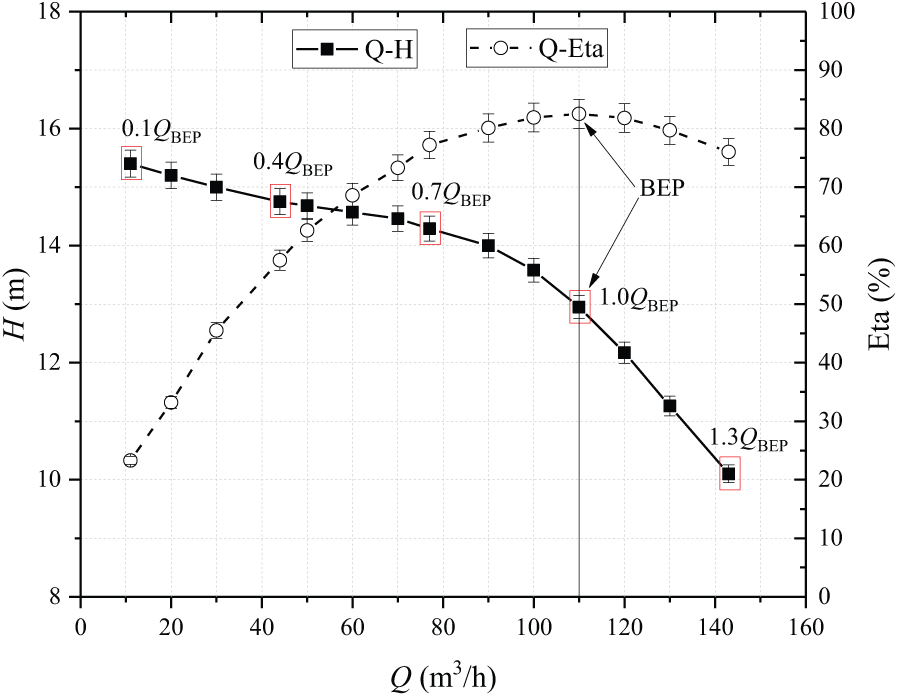
Hydraulic performance data for the vertical pump.
Vibration causes analysis
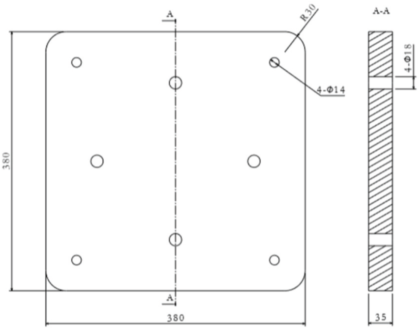
By checking the pump structure, it can be found that the original baseplate is weak. It is stamped in steel with a thickness of 5 mm, as shown in Figure 5. The material code of steel is C45 according to DIN (German Institute for Standardization) standard. To verify that the weak baseplate is the root cause for the higher vibration, the comparison tests were made for the pump model with an original weak baseplate and an “infinitely rigid” baseplate. The test setup is shown in Figure 6. Figure 7 shows the maximum vibration amplitude of different setups corresponding to different regions at different flow rates, where the vibration amplitude is expressed by the root mean square (RMS) of the velocity. According to the ISO 10816 standard, for rotating machinery, the maximum vibration amplitude is used as the criterion for judging the quality of the vibration level. For rotating machines up to 15 kW, the maximum vibration amplitude allowed for long-term stable operation is 1.8 mm/s. 29 It can be seen from Figure 6(a) that the vibration amplitude of the original baseplate exceeded 1.8 mm/s. Taking vibration data at 0.1QBEP as example, the vibration amplitude of the motor region is the highest, and its value is 4.05 mm/s. The vibration amplitude of pump region is lower than motor region and its value is 1.5 mm/s. The vibration amplitudes of pipeline region and baseplate region are relative small, values are 0.55 and 0.3 mm/s, respectively. However, by replacing the original weak baseplate with an “infinitely rigid” baseplate, the vibration amplitude of pump unit drops significantly and the highest amplitude is about 1.6 mm/s. Moreover, it can be found that the vibration amplitude at the BEP is the smallest, and the vibration amplitude increased under the large flow rate and the small flow rate conditions. This trend was validated for the centrifugal pump in the literature before. 19 This is mainly because when the centrifugal pump operating near the BEP, the internal flow is the most uniform, and unstable flow phenomena such as flow separation, backflow, and shock are not easily generated inside the impeller and the volute. At the same time, the rotor system in which it operates is subjected to the smallest hydraulic imbalance force.

Structure of original baseplate.

Different baseplate setups for pump vibration test: (a) pump is mounted on an original weak baseplate and (b) pump is mounted on an “infinitely rigid” baseplate.
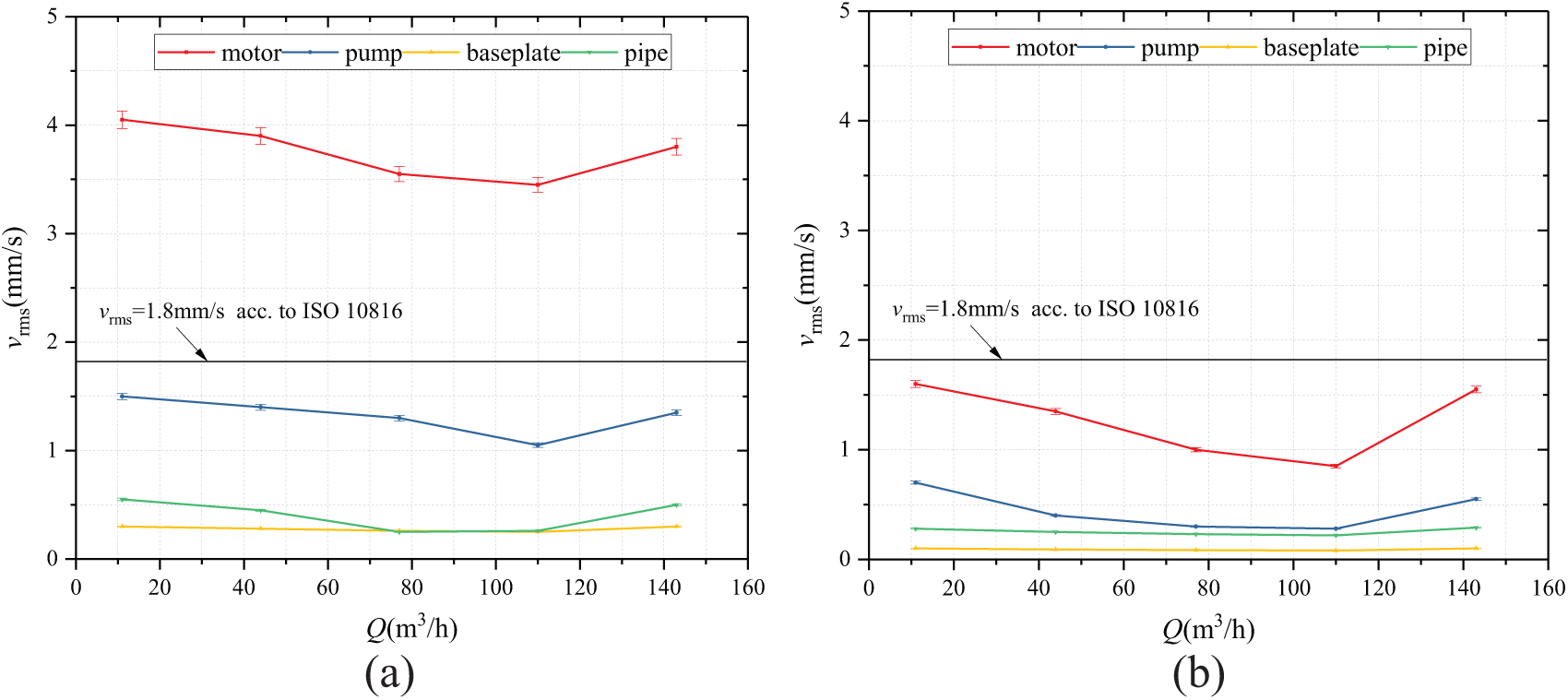
Vibration data of the original baseplate and the “infinitely rigid” baseplate: (a) pump is mounted on original weak baseplate and (b) pump is mounted on a “infinitely rigid” baseplate.
In addition, the natural frequencies of the pump were obtained experimentally and numerically to help understand whether the resonance happened during the running process. The impact test was performed for the pump unit in a standstill condition. Table 2 shows the first three natural frequencies of the pump with original weak baseplate. It is found that the first two natural frequencies of the original model are small. The second natural frequency measured by the impact test is 36.2 Hz, which is close to the rotation frequency of the vertical pump 29.5 Hz. Consequently, it can induce the resonant vibration phenomenon of the pump unit. Meanwhile, the modal analysis of the pump model was carried out by the finite element method. The calculation results are shown in Figure 8. The same boundary conditions were defined for the test and simulation, despite the fact that some simplifications were made for finite element analysis model, for instance, ignoring the interfacial friction force and pretension force of bolts in the simulations. Therefore, there was a gap between the test and calculation data. It was observed that the first, second, and third vibration modes of baseplate are the transverse deformation, longitude deformation, and torsional deformation, respectively. Under the action of external force, the motor area with a high center of gravity was prone to large vibration. Therefore, in order to improve the vibration of the vertical pump, it is necessary to optimize the baseplate of the vertical pump for enhancing its stiffness and increasing the natural frequency of pump.
Natural frequencies of the original model.


Modal analysis results of the original model: (a) first mode, (b) second mode, and (c) third mode.
Design of new baseplate
Topology optimization
The solid isotropic microstructures with penalization (SIMP) method is a kind of variable density method, which is widely used for static dynamic structure optimization due to its robustness and fast computation.30,31 Thus, in this study, this method is employed, where the key idea is that the stiffness of the material with penalty is assumed to be

where ρ is the relative density, p is the penalization factor, and E is the elastic modulus.
The SIMP method is based on the discrete division of the structure, wherein each element is assumed as a variable. The density is varying between 0 and 1. There is a correspondence between the value of density and the material physics. If the density is 1, then the materials are kept, else if the density is 0, then the materials are removed. The volume fraction is the constraint for the baseplate optimization. The objective function for the topology optimization is the maximum stiffness or the minimum compliance of the baseplate. The topology optimization mathematical model for the baseplate is as follows
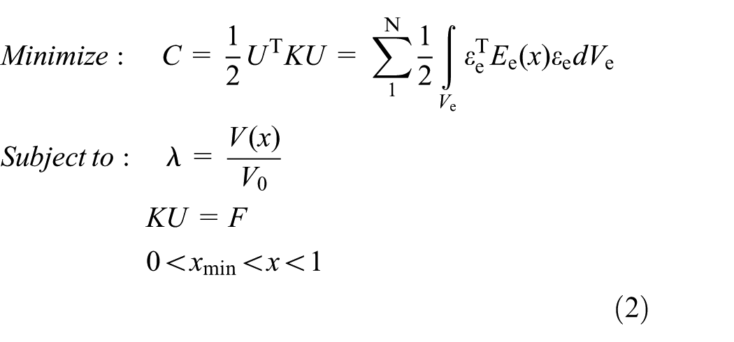
where C is mean compliance of energy, U is global displacement vectors, K is global stiffness matrix, N is the number of finite elements of the mesh, Ee is the elastic matrix of the element, εe is strain vector of the element, Ve is volume of the element, V(x) is the material volume after optimized, V0 is initial design volume, λ is volume fraction after optimized, F is globe force vectors, x is vector of design variables, and xmin is minimum relative density.
To eliminate the checkerboard pattern and mesh-dependency issues of the topology optimization, one additional filtering function can be used. A filtering function constructs a sub-domain Ωa, where an element a is defined as center, and rmin is the radius of sub-domain. All the elements in the sub-domain Ωa are used for calculating the elastic energy of the filtered element a

where Ea is the elastic energy after filter; l is the element number of sub-domain Ωa; and dab = rmin – rab is the weight coefficient, rab is the distance from center of element b to center of element a.
The initial model of the baseplate is shown in Figure 9. The dimensions of baseplate and positions of hole are consistent with the original model. The basic material GS-60 (DIN standard) is applied for the initial baseplate, because it is manufactured by the casting method. The finite element model was constructed for the initial baseplate. Two boundary conditions were defined for calculation. A gravity force of 1350 N applied on top surface between baseplate and pump casing was defined as load A. And, the fixation of the four mounting holes was defined as load B. The boundary conditions are presented in Figure 10.
Initial design model of baseplate for optimization.

Boundary conditions for calculation.
Afterward, the accuracy of the objective function and the range of the volume fraction λ were defined. In this article, the topology optimizations were performed with 80%, 60%, and 40% volume fractions, respectively. The volume fraction λ = 80% means that at least 20% of the materials need to be removed after optimization. Finally, the ANSYS 16.2 Workbench was selected to perform the topology optimization processes. The optimization strategy is to reduce the weight of the baseplate as much as possible while ensuring the maximum rigidity of the baseplate. The criteria for the optimization is that the minimum natural frequency of the new model needs to exceed 39 Hz, that is, 1.3 times the rotation frequency fr. 1 This criteria was defined for eliminating the resonant vibration at the rotation frequency fr = 29.5 Hz.
Optimization results
Figure 11 shows the topological optimization results of the baseplate under different volume fractions. The three layouts were presented: the first layout indicated the density distribution of the top surface of baseplate; the second layout indicated the density distribution of the middle section surface of baseplate; and the third layout indicated the final shape of baseplate after optimization. The red area is the part with density close to 0, which can be removed. The gray area is the density close to 1, which is a retainable part. Finally, based on the outputs from calculation, the optimization result of volume fraction λ = 60% was selected as the reference object for the structural design. Looking at material distribution of baseplate after topology optimization, the gray regions of baseplate indicated that the ribs should be considered in these regions when designing the new structure. From the static force analysis results of the baseplate, it is necessary to arrange the reinforcing ribs at the positions of the four connecting holes between baseplate and pump casing to improve its lowest natural frequency. Because the position of the connecting holes is subject to large deformation. In other words, the stiffness of these regions is weak and cannot withstand external gravity and torsion forces. Also, the ribs need to be designed for the four mounting holes regions. In addition, according to the requirements of the casting process, the draft angle of 5° was set for new baseplate. The thickness of baseplate was controlled between 10 and 12 mm for easy casting. By considering the above design factors, the final design of the baseplate is shown in Figure 12. It has a weight of 15.97 kg and the mass reduction rate is about 60%.
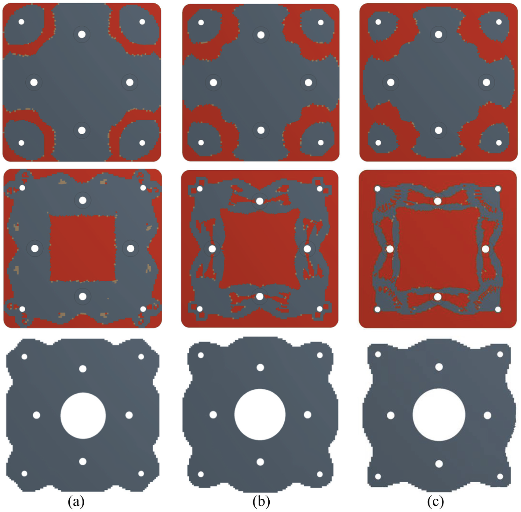
Optimization results under different volume fractions: (a) λ =80%, (b) λ =60%, and (c) λ =40%.

New baseplate after topology optimization.
Results and discussion
Numerical and experimental validation
The vibration tests and the numerical simulations were carried out to investigate the vibration behaviors of the optimized pump model with new baseplate. Table 3 shows the experimental and calculated values of the natural frequencies for the optimized vertical pump model. It can be found that the first and the second natural frequencies of the optimized model are greatly improved. The first natural frequency obtained by experiment was 65 Hz, but for the original one, this value was only 20.7 Hz. It could be noted that the natural frequency of optimized model was higher than the criterion (i.e. 39 Hz defined before) and can effectively avoid the occurrence of resonance. Reviewing the deformation of the baseplate at different modes in Figures 8 and 13, it is observed that the deformation of the optimized baseplate was from 0.4 to 0.55 mm in three modes. However, the deformation of the original baseplate was from 0.8 to 0.85 mm. The deformation was reduced largely using the new baseplate. It is further demonstrated that the stiffness of the baseplate has been greatly improved after optimization, which also enhances the natural frequency of the pump unit correspondingly.
Natural frequencies of the optimized model.


Modal analysis results of optimized vertical pump model: (a) first mode, (b) second mode, and (c) third mode.
Figure 14 shows the vibration test results of the vertical pump with optimized baseplate. It can be found that the vibration amplitude of the optimized vertical pump is less than 1.8 mm/s under different flow conditions. The vibration amplitude of the motor region is the largest, and the corresponding amplitudes at the 0.1QBEP, 1.0QBEP, and 1.3QBEP conditions are 1.75, 0.95, and 1.7 mm/s, respectively. In contrast, the motor region of the original model in Figure 7 has corresponding amplitudes of 4.05, 3.45, and 3.8 mm/s under these three operating conditions, respectively. Therefore, it has been experimentally verified that the optimized baseplate can effectively reduce the vibration amplitude of the pump and make it fulfill the limitation of ISO standard.

Vibration data of the optimized model under different flow rates.
Vibration characteristics analysis
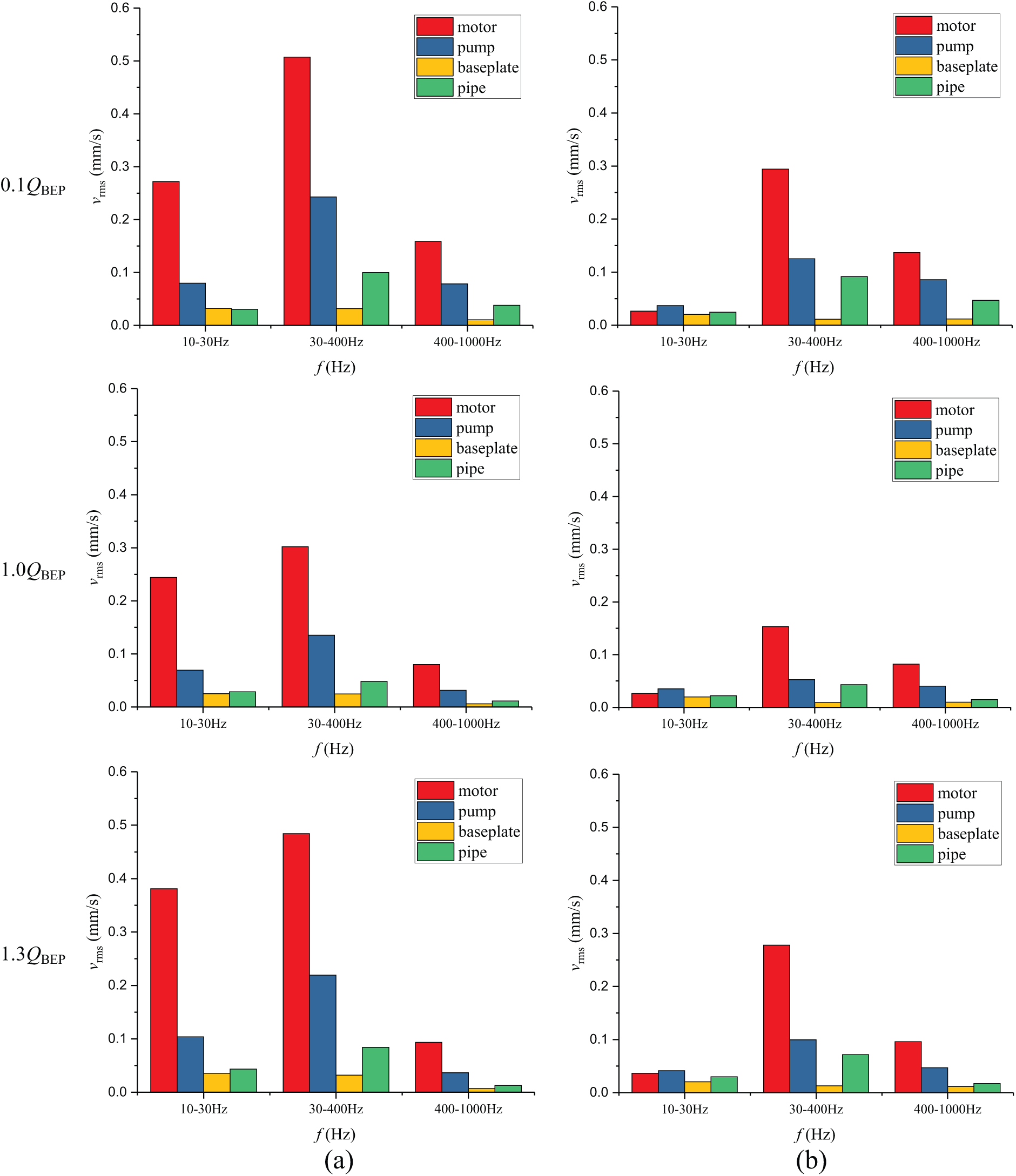
Figure 15 shows the vibration characteristics of the original model and the optimized model under different flow conditions. In this article, the frequency spectrums of vibration characteristics in the range of 10–1000 Hz were selected as the study object, because most of the important vibration information of pump can be covered in this frequency range. Using the 1/3 octave-band filter technique to perform fast Fourier transform (FFT) on the vibration velocity signals, the frequency-domain characteristics and the main excitation frequencies under different flow conditions were obtained. For ease of analysis, the entire frequency domain is divided into low-, medium-, and high-frequency bands. The low-frequency band is mainly distributed between 10 and 30 Hz, that is, lower than the pump rotation frequency; the high-frequency band is 400–1000 Hz; and the medium-frequency band is 30–400 Hz. It is found that the main excitation frequencies of the vertical pump were distributed in the medium-frequency band. From the frequency-domain characteristics, the vibration amplitude of different regions for the pump unit, that is, from high to low, the motor region, pump region, pipeline region, and baseplate region can be determined. The main excitation frequencies of the four regions were basically the same. For the original model, the main excitation frequencies were 31.5 Hz, 160 and 200 Hz. They were mainly caused by the rotation frequency and the blade passing frequency of the pump. The largest vibration amplitude was caused by the primary excitation frequency of 31.5 Hz. It is supposed that a natural frequency 36.2 Hz was excited to resonance by a close-by discrete rotation frequency of 29.5 Hz. However, by analyzing the vibration characteristics of the optimized model, we can observe that the main excitation frequencies were 80, 160, and 200 Hz, and no peaks can be found at 31.5 Hz. This verifies that the optimized model changes the natural frequency of the vertical pump due to the increase in the rigidity of the baseplate. The first natural frequency was increased from 20.7 to 65 Hz after using the optimized baseplate. Thereby, the resonance is eliminated effectively.

Vibration characteristics of the original model and the optimized model: (a) original model and (b) optimized model.
Moreover, it is found that the vibration amplitude of the original model at the primary excitation frequency of 31.5 Hz remained basically unchanged at different flow rates and its maximum value was around 2 mm/s. Also for the optimized model, the vibration amplitude at the primary excitation frequency of 80 Hz did not change much and its maximum value was around 0.8 mm/s. It is indicated that the change in flow rates gave little effect on the vibration characteristics at the primary excitation frequency. This is mainly due to the fact that the vibration at the primary excitation frequency of the two models is mainly affected by the imbalance of the rotor. And, the less effect comes from the hydraulic interaction force. However, for the secondary excitation frequency of 160–200 Hz, the vibration amplitude under this frequency band was lowest at the BEP 1.0QBEP. As for the original model, the maximum value under this frequency band was about 0.3 mm/s; however, for the optimized model, its maximum value was about 0.2 mm/s. Under the condition of the small flow rate 0.1QBEP, the corresponding amplitudes of the original model and optimized model increased up to 1 and 0.45 mm/s, respectively. The reason is that the secondary excitation frequency was mainly affected by the blade passing frequency. Basically, the hydraulic imbalance force under the blade passing frequency is lowest near the BEP, and it increased under the off-design conditions.
Finally, comparing the vibration characteristics of the original model and the optimized model under the low-frequency band (10–30 Hz), it can be found that, in the motor region, the averaged vibration amplitude of the optimized model under the low-frequency band is about 0.3 mm/s, and for the original model, its value is about 0.03 mm/s (see Figure 16). The main reason is that the stiffness of the optimized model is significantly higher than that of the original model. This provides a good resistance for the low-frequency vibration, especially for the motor and pump with higher center of gravity. In contrast, the vibration responses under the high-frequency band (400–1000 Hz) are presented quite differently by comparing with those under low-frequency band and medium-frequency band. The averaged vibration amplitudes of the original model and optimized model almost keep in the same level. In other words, the stiffness of the baseplate is not a significant influence on the vibration characteristics under the high-frequency band. Because the first three natural frequencies of the original model and optimized model are lower than 400 Hz, it is hardly to get the resonant vibration under the high-frequency band. Also, it is known that the excitation vibration under high-frequency band is mainly caused by the second- or the third-order blade passing frequency (∼360 or ∼720 Hz) in a centrifugal pump. These excitation frequencies are not linked to the stiffness of pump structure.
Averaged vibration amplitude of the original model and the optimized model under different frequency bands: (a) original model and (b) optimized model.
Conclusion
In this article, the influence of baseplate structure on pump vibration during operation has been investigated experimentally and numerically. It was found that the weak stiffness of baseplate was the root cause of pump vibration for a vertical pump. The resonance was observed at 31.5 Hz in the spectrum, and the maximum vibration amplitude of the original model reached to 4.05 mm/s. It exceeded the limitation of ISO standard, therefore the vertical pump could not operate for a long time.
Furthermore, the topology optimization was employed to modify the structure of baseplate for enhancing the stiffness and increasing the natural frequency. The new baseplate was manufactured by the casting method and assembled into a new model. The experimental tests and the numerical simulations were carried out to investigate the vibration behaviors of the optimized model. Results showed that the stiffness of baseplate increased largely and the natural frequency of the optimized model up to 65 Hz. It was found that the maximum vibration amplitude of the optimized model was lowered down to 1.75 mm/s. It basically fulfilled with the standard requirement.
In addition, the vibration characteristics of a vertical pumps was investigated using the experimental measurements and 1/3 octave-band filter technique. It was observed that the domain-exciting frequencies for the pump vibration were distributed in the medium-frequency band (30–400 Hz). The peak frequencies of the original model were found at 31.5, 160, and 200 Hz at different flow rate conditions. It was demonstrated that the resonance, the unbalance of rotor (rotation frequency of pump is 29.5 Hz), and the blade–tongue interaction (blade passing frequency is 177 Hz) were the main inducers for the pump vibration. However, the resonance was eliminated for the optimized model, and its peak frequencies were transferred to 80, 160, and 200 Hz. Moreover, it was found that the vibration amplitude under the low-frequency band has a major reduction for the optimized model because of the new stronger baseplate.
Finally, the methods used for this study could be useful for the other kinds of turbo or hydro machineries. There were still some limitations of this research. In future, it would be more comprehensive to involve the whole pump components, for example, pump casing, motor stool, and impeller, as the optimization target in order to get more vibration reduction.
Footnotes
Handling Editor: Mohammad Arefi
Declaration of conflicting interests
The author(s) declared no potential conflicts of interest with respect to the research, authorship, and/or publication of this article.
Funding
The author(s) disclosed receipt of the following financial support for the research, authorship, and/or publication of this article: This work was supported by the National Natural Science Foundation of China (grant nos 51609212, 51606167, and 51779226) and the China Postdoctoral Science Foundation (grant no. 2016M590546).