
Abstract
A dual planetary gear hybrid electric vehicle is introduced in the paper. The speed and torque relations between different components of the power split hybrid system are systematically established using the lever analogy. Based on the electric power balance, the influence of the ratio between the engine speed and output speed of the power coupling system on the hybrid electric vehicle powertrain transmission efficiency is revealed, and the transmission efficiency optimization strategy is further proposed. Since some engine operation points are distributed in the low-efficiency region, the engine torque control strategy is designed using fuzzy control algorithm. The fuzzy membership function and fuzzy rules are optimized by particle swarm optimization to reduce the bad influence of expert experience and knowledge on the derivation of optimal engine torque. The vehicle powertrain and the control strategy models are established based on AVL/Cruise and MATLAB/Simulink platforms, and the joint simulation is conducted. Simulation results show that the proposed optimal energy management strategy can optimize the operation points of the engine. The final value of the battery state of charge is kept within a reasonable range, and the equivalent fuel consumption of the whole vehicle is reduced by 10.26% compared with that the transmission efficiency optimization control strategy.
Keywords
Introduction
Power split hybrid systems are generally divided into the following three types: input split, output split, and compound split. In general, the power split hybrid system is usually composed of the planetary gear set. The engine speed and torque are decoupled from the rotational speed and torque of the wheel.1,2 The power split hybrid system splits the engine power into mechanical path and electrical path. The mechanical path of the vehicle delivers the engine power directly to the wheels by planetary gears. In the electrical path, the engine power is converted into electric power to drive the vehicle or charge the battery. 3 The virtual forces with different degrees of freedom have been studied in the planetary gear sets, which determine the direction of power flow, and the power circulation phenomenon has also been analyzed in the transmission system. 4 In the input split hybrid power system, the system transmission efficiency is high when the vehicle runs at low speeds, and it is rapidly reduced when the vehicle runs at high speeds. 5 However, the output split hybrid power system shows the opposite phenomenon. 6 The high transmission efficiency range is narrow and the transmission efficiency decreases with the reduction of vehicle speed. Both the output split and the input split systems have only one mechanical point. 7 J Kim has made detailed comparisons between the transmission efficiencies of dual planetary structure and single planetary structure. It is indicated that the ideal transmission ratio is easier to be obtained by the dual planetary structure, which leads to the high operation efficiency range of the vehicle. 8 W Zhuang et al. 9 also proved that passenger cars should adopt dual planetary hybrid powertrain for the advantages of fuel economy.
For power split hybrid electric vehicles (HEVs), the maximum transmission efficiency happens when the power of all electric machines is zero, and the engine operates at the mechanical point. It means that the engine power is only delivered to the vehicle driving axle through the mechanical path, and there is no conversion losses between electrical and mechanical energy. However, if the engine only operates at the mechanical point to ensure a good transmission efficiency, the energy buffer effects of the battery cannot be fully applied, and the engine may also show bad fuel consumption rate. There should be a trade-off between the engine fuel consumption rate and the transmission efficiency. Most papers have optimized the energy management strategies to improve the vehicle fuel economy by minimizing the engine fuel consumption rate. The transmission efficiency optimization (TEO) strategy based on mechanical point can be designed by selecting an appropriate engine speed. When the transmission efficiency is emphasized, the optimal engine speed that makes the mechanical point happen is usually derived. Due to the 2 degrees of freedom of the power split device, both the engine speed and torque can be controlled freely. Nevertheless, the existing literatures just focus on the transmission efficiency to improve the engine operation speed. There is a lack of further engine torque optimization on the basis of the TEO strategy to further improve the operating point of the engine.10,11
In this article, a novel dual planetary gear HEV is introduced, and the TEO strategy is designed based on the optimization of system transmission efficiency. On this basis, we further proposed the engine torque optimization strategy with fuzzy strategy aiming at the novel power split configuration. The fuzzy membership function and fuzzy rules are optimized by particle swarm optimization (PSO). Joint simulations for the power split HEV with the proposed the strategy are evaluated and compared.
Specifically, the rest of the paper is organized as follows: power split characteristics of the power coupling mechanism is analyzed based on lever analogy in section “The power coupling mechanism analysis.” To improve the transmission efficiency, TEO strategy is established in section “TEO control strategy.” Section “Fuzzy optimization strategy based on PSO algorithm” adopts the fuzzy strategy and PSO algorithm to further optimize the engine operation points. Simulation results are analyzed in section “Comparison and analysis of simulation results,” followed by the conclusion in section “Conclusion.”
The power coupling mechanism analysis
The proposed power coupling mechanism with dual planetary gear sets is shown in Figure 1, which consists of the engine and two electrical machines MG1 and MG2. The engine is connected to the front planet carrier C1 through clutch CR1 and brake CB1. The purpose of adding the clutch CR1 is to reduce the effect of engine inertia and protect the engine when the vehicle is running. The motor MG1 is connected to the front sun gear S1, and the motor MG2 is connected to the rear sun gear S2 through clutch CR2. The front planet carrier C1 is connected to the rear ring gear R2, and the front ring gear R1 is connected to the rear planet carrier C2.
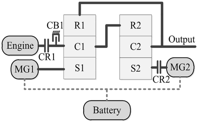
Power split hybrid electric vehicle.
In the paper, steady-state analysis of the power coupling mechanism is conducted using lever analogy.12,13 The equivalent lever diagram is shown in Figure 2. In the figure, the lever distance from the engine to the output is assumed to be 1, while the lever distance from MG1 to the engine is set to be a, and lever distance from MG2 to the output is defined as b. The lever model shown in Figure 2 is a 2-degree-of-freedom system. The mechanical point can be obtained when the speed of the MG1 or the MG2 is zero. 14 Therefore, there are two mechanical points in the proposed power coupling system.

Lever model of the power coupling system.
According to the speed and torque relations within the planetary gear sets, the equivalent steady-state equations can be obtained when the gears are assumed to be rigid
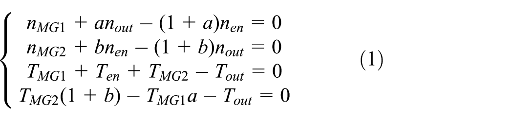
where nMG1 and nMG2 are the speeds of MG1 and MG2; nout is output shaft speed; Ten is the engine torque; TMG1 and TMG2 are torques of MG1 and MG2; Tout is the output torque; nen and Ten are the speed and torque of the engine, respectively.
In the hybrid driving process, the engine is the power source. When the output power of the battery is zero, according to the power balance PMG1 = –PMG2,14,15 we have

where PMG1 and PMG2 represent the power of MG1 and MG2, while ηMG1 and ηMG2 represent the efficiencies of MG1 and MG2, respectively.
In the simulation, it is assumed that both the efficiencies of MG1 and MG2 are 0.85. 16 Consequently, the transmission efficiency F(i), the electric power ratio E(i), and the transmission ratio i are defined as
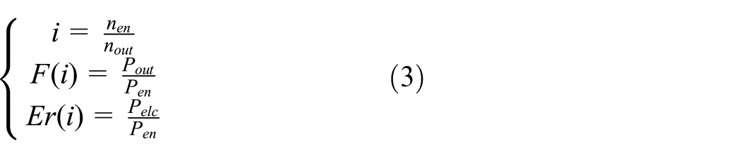
where Pout is vehicle output power; Pen is engine output power; Pelc is electrical output power of the battery. The characteristic parameters of the front and rear planetary gear sets are 1.842 and 2.48, respectively. Namely, k1 = 1.842, k2 = 2.48. The ratios of the speeds and torques of electric machines to those of the engine are shown in Figures 2 and 3. When the torque of MG2 and the speed of MG1 are zero, the electric power is zero. Then, the first mechanical point i1 is obtained. In the same way, the mechanical point i2 can be obtained when both the torque of MG1 and the speed of MG2 are zero. It can be seen that the transmission ratio i decreases with the increase of the vehicle speed when the engine speed is certain. As shown in Figures 3 and 4, maximum transmission efficiencies at the two mechanical points can be observed. At the mechanical points, the electrical power ratios are zero and the electric machines do not participate in the work. 17 As a result, there is only mechanical path in the system and the system operates without electrical energy losses. The vehicle transmission efficiency drops rapidly as the transmission ratio decreases when i < i1. When i > i2, the electrical power increases and the transmission efficiency decreases slowly with the increase of the transmission ratio. The torque ratios and speed ratios of the two electric machines are smaller when the transmission ratio is between two mechanical points, resulting in higher transmission efficiency and smaller electric power. In addition, it is apparent that the electric power of MG1 and MG2 are very large when the transmission ratio becomes too large or too small. Such situations should be avoided.
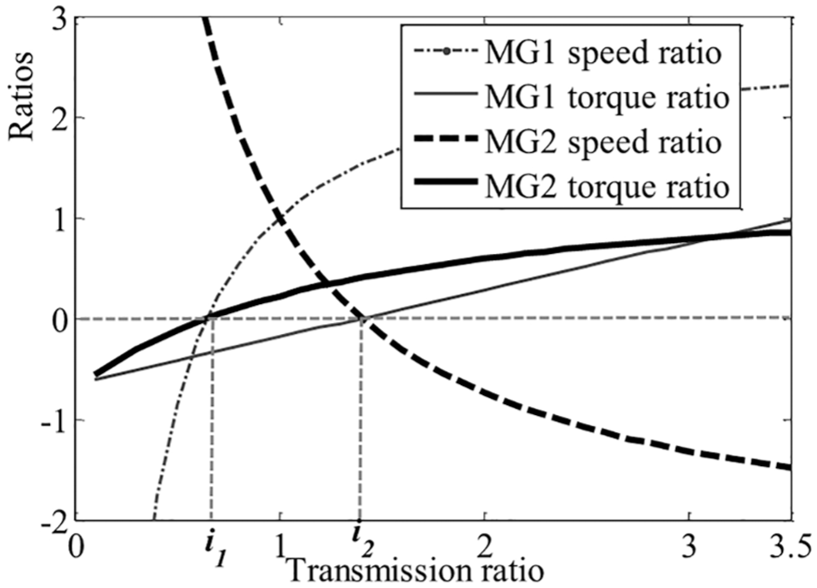
Speed ratio and torque ratio.

Transmission efficiency and electric power ratio.
TEO control strategy
The control scheme of the power split HEV is shown in Figure 5. The required torque Treq is calculated by the driver module with the difference between vehicle actual speed Vact and vehicle required speed Vreq. Hierarchical control is adopted in energy management system. The operation mode is first determined based on the vehicle current state in the mode decision module. The torques of different required components are further obtained in the torque distribution module; these torque commands are applied to the powertrain of the HEV. Finally, state variables such as battery state of charge (SOC) and Vact, are provided to the driver and energy management system.

Control scheme of the power split HEV.
In addition, in order to start the engine under the optimal conditions and prevent the engine from starting and stopping too frequently, an engine start–stop module was built in the mode decision module, as shown in Figure 6. The engine start condition is that switch equals 1, while switch equals 0, the engine stops.
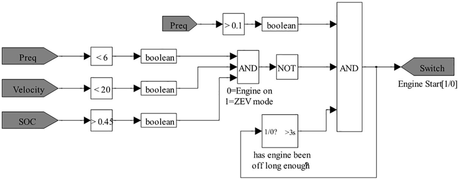
Engine start–stop module.
The optimization algorithm is meaningless when the vehicle fuel consumption in the high-efficiency area is greater than the fuel consumption in the non-efficient area. In order to avoid the power circulation phenomenon and reduce vehicle fuel consumption, the TEO strategy based on the vehicle transmission efficiency is designed to optimize the system transmission efficiency.
The schematic diagram of the TEO control strategy is shown in Figure 7. The vehicle operates in charging standstill mode when the battery SOC is less than the predefined value and the vehicle speed is zero. The engine drives MG1 to generate electricity and charge the battery. If the battery SOC value is higher than the predefined value, the vehicle is in the parking mode. The vehicle selects pure electric mode when the vehicle demand torque is greater than zero and the transmission ratio R is zero. MG2 drives the vehicle alone. The vehicle selects regenerative braking mode or mechanical braking mode when the vehicle demand torque is less than zero. MG2 converts mechanical energy into electrical energy when the vehicle is in regenerative braking mode, and the electric energy is stored in the battery. Electric energy losses happen when the vehicle runs on both sides of two mechanical points, which seriously affects the system efficiency. In order to prevent the engine from operating in the above two sections, the value of is is set in this article. When the transmission ratio R is greater than zero and less than is, or that the transmission ratio R is greater than is, the vehicle enters the combined driving mode, and the engine speed is set to operate at the mechanical point i1 or the mechanical point i2, respectively.

The transmission efficiency optimization strategy.
Fuzzy optimization strategy based on PSO algorithm
Fuzzy control mainly depends on engineering expertise and fuzzy information can be obtained based on fuzzy inference under the premise of no precise model. 18 In order to further optimize the engine operating point while ensuring the system transmission efficiency, this article designs a two-dimensional fuzzy controller. The particle swarm algorithm is applied to optimize the fuzzy membership function and control rules automatically.
The input variables are set to be q and r, and the output variable is k. q is defined as the ratio of the demand torque to the optimal engine torque at the current engine speed. r is defined as the ratio of the current battery SOC to the initial battery SOC. The output variable k is the engine torque coefficient. When the engine starts to participate in the work, the input variables q and r are decided, and the optimal choice is realized according to the pre-established rules. Ultimately, the optimal engine torque is derived. Figure 8 shows the fuzzy control scheme of the engine torque. SOCint represents the initial SOC value, while Topt is the optimal torque at the current engine speed.

Fuzzy control scheme of the engine torque.
The fuzzy domain of the input variable q is set to be [–5, 5], and the input variable q is divided into nine fuzzy subsets: {NVB, NB, NM, NS, ZO, PS, PM, PB, PVB}. The fuzzy domain of the input variable r is set to be [–5, 5], and the fuzzy subset is {NVB, NB, NM, NS, ZO, PS, PM, PB, PVB}. The fuzzy domain of the output variable k is [–5, 5], and the fuzzy subset is {NVB, NB, NM, NS, ZO, PS, PM, PB, PVB}.
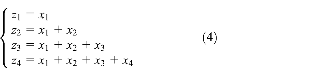
In order to reduce the influence of expert experience knowledge on the vehicle energy optimization results, PSO algorithm is used to optimize fuzzy rules and membership functions of the fuzzy controller. The reasonable coding method also has an important influence on the performance of PSO algorithm. The triangle membership function is selected because of its briefness and better control sensitivity. 19 Figure 9 denotes the output variable of the membership function, where four parameters (x1, x2, x3, and x4) are defined to determine the shape.

Optimization parameters for membership function.
The satisfaction relationship is as follows
In the same way, the other two input variables of the membership functions are represented by mathematical formulas. In this article, a total of 91 parameter variables need to be optimized. The first 12 dimensions are used to describe the output variables and input variables, and the real number coding is adopted. The remaining 81 dimensions are used to describe 81 fuzzy rules, using integer coding.
The basic principle of the PSO algorithm comes from research on the collective predation behavior of birds, which can be described mathematically.20,21 To find out the optimal solution in the S-dimensional search space, the group is constructed by m particles, and each particle may be the potential optimal solution for the problem to be solved. The velocity of each particle is vi = (vi1, vi2,…, vis) and the location is described as xi = (xi1, xi2,…, xis). The particle is searched in the S-dimensional space according to certain optimization rule.
The particle swarm gets two optimal values at every moment, one is the individual local optimal value pbest, which is recorded as Pis = [Pi1, Pi2,…, Pis], and the other is the group optimal value gbest, denoted as Pgs = [Pg1, Pgg2,…, Pgs]. Because the particles have a memory function, the two optimal values can be continuously compared. The speed and location of the particle will be updated until the optimal result is found. Since the fuel economy of HEV can be featured by the engine fuel consumption and the battery SOC, the objective function of the optimization problem is set to be the equivalent fuel consumption of the vehicle, that is, the sum of the engine fuel consumption and the equivalent fuel consumption which is converted by electric energy consumption, as shown by equation (5)

where f(x) is the objective function, Eng_fuel represents engine fuel consumption, Bat_fuel represents electric energy consumption, and s represents the conversion coefficient between engine fuel and electric energy.
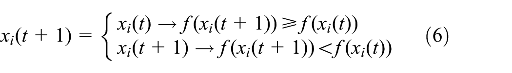
Equation (6) indicates the best location of the ith particle xi(t); t represents the iteration number. The update of the particle velocities and locations are shown in Figure 10

The sketch map of the location and velocity of particles.
In the process of optimization, the velocity and position of particles are calculated by

where i = [1, m], s = [1, S]; ω is the inertia weight coefficient; c1 and c2 are defined as learning factors; r1 and r2 are random numbers between 0 and 1; the range of vis is [–vmax, vmax], while vmax is a constant.
Simulink and CRUISE are used for joint simulation with MATLAB_DLL interface. The schematic diagram of the PSO optimization is shown in Figure 11. First, the prepared M file is used to invoke CRUISE, and the engine fuel consumption and electrical power data of electric machines can be obtained. The membership function and fuzzy control rules are optimized by the PSO algorithm. The Isight integration idea 21 is adopted to create a “Run_CRUISE.bat” file and integrates the vehicle control strategy run in Simulink and the vehicle model run in CRUISE. The optimization cycles are repeated.

Diagram of PSO algorithm.
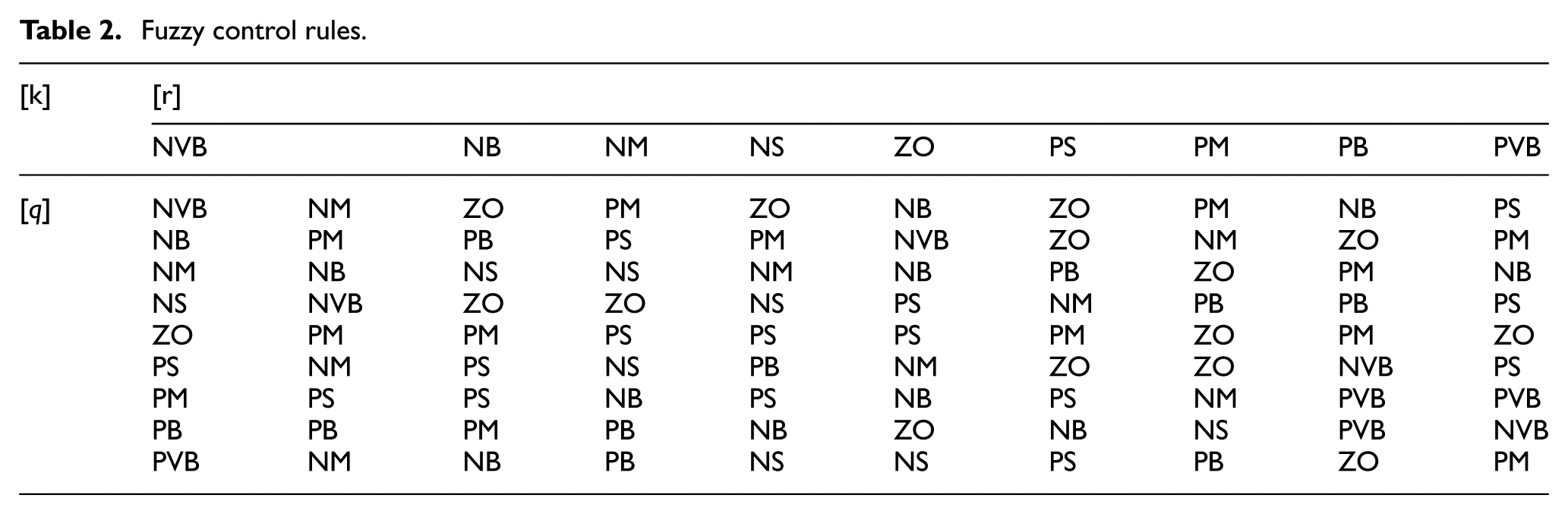
The parameters of the PSO algorithm are shown in Table 1. The optimized membership functions and control rules are shown in Figures 12 –14 and Table 2. The surface of optimal fuzzy rules obtained with PSO algorithm is shown in Figure 15.
Related parameters of particle swarm optimization.


Membership function of input variable q.

Membership function of input variable r.

Membership function of output variable k.
Fuzzy control rules.

Fuzzy rules surface.
Comparison and analysis of simulation results
In order to verify the control effect of the TEO strategies with and without engine torque optimization, the hybrid vehicle model based on AVL/CRUISE is built, and the two control strategies are constructed in MATLAB/Simulink software. The hybrid vehicle model and the control strategies are combined through DLL file. The vehicle is tested under New European Driving Cycle (NEDC) condition. The parameters of the main components are shown in Table 3.
Parameters of components and vehicle.
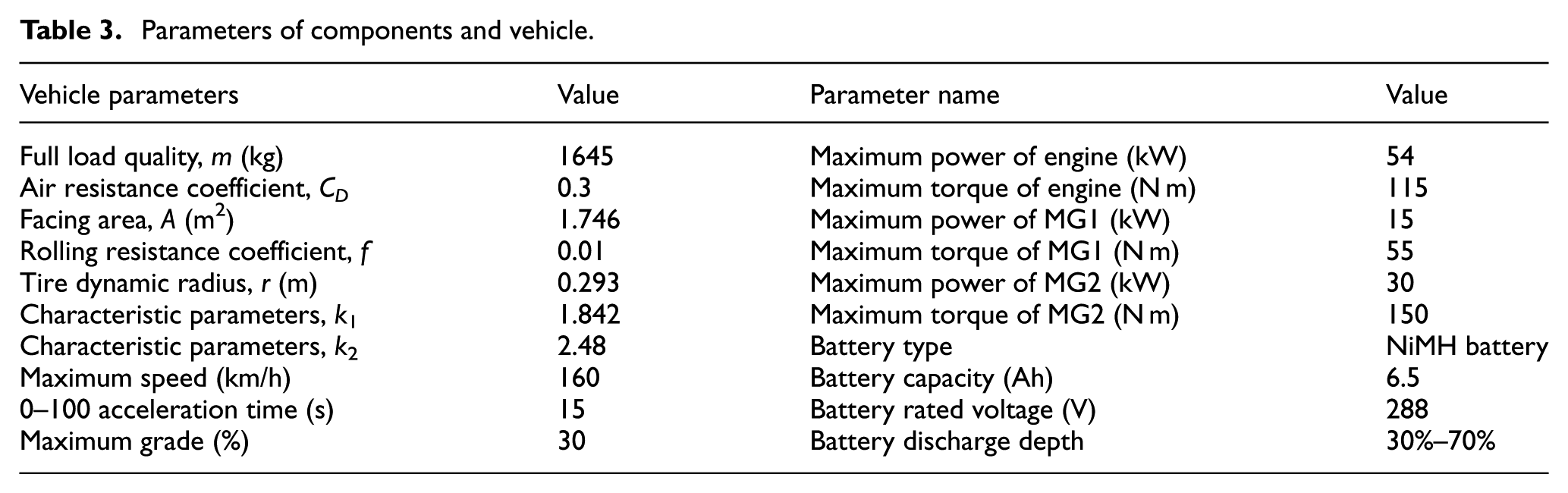
Figure 16 compares the simulation results of all power sources with different strategies. From Figure 16(a), it can be seen that the actual vehicle speed follows the target speed well and the error is within the acceptable range. The result verifies the effectiveness of the proposed strategy. When the vehicle operates in the urban area, it can be seen from Figure 16(b)–(d) that the vehicle is in pure electric mode most of the time with both strategies, and the MG2 participates in driving the vehicle. When the vehicle operates in the charging standstill mode, the MG1 is driven by the engine to charge the battery. As a result, the battery SOC is kept within the desired range. The operation time that the vehicle operates in the charging standstill mode with the PSO optimization is less than the running time when the TEO strategy without PSO optimization is applied. The frequency of the engine start–stop is smaller, which effectively reduces engine fuel consumption.

Simulation results under NEDC condition.
When the vehicle is in the suburban scenario, it can be seen from Figure 16(b)–(d) that the vehicle mainly works in the combined driving mode. The engine and the electric machines coordinate to drive the vehicle. With the TEO strategy, it can be seen that higher transmission efficiency of the system is ensured. Between 1040s and 1130s, with the PSO optimization, the output power of the engine is larger. The output power of MG2 is negative and increases to charge the battery, and the battery SOC is maintained in a better range. MG1 is mainly used to generate electricity and regulate the engine speed. Compared with the TEO strategy without PSO optimization, the engine operation time is reduced by 14.8 s after optimization with PSO algorithm in the entire cycle condition, and it plays a great role in reducing the fuel consumption of the whole vehicle.
Figure 17 shows the transmission ratio with the two strategies. It can be seen from the figure that the vehicle transmission ratio basically runs at the mechanical point between 960 and 1160 s when the vehicle is in the hybrid drive mode. The electric output power is relatively small and the efficiency of the whole vehicle system is high. Figure 18 shows the battery SOC curves under the two strategies and the trends are basically the same. In the urban driving scenarios, the vehicle speed variation is relative small and frequent stops happen. The battery SOC is maintained between 0.65 and 0.7. When the vehicle is operating in suburban conditions, the electric output power is small, the internal loss of the system is reduced by maximizing the transmission efficiency which is selected as the objective, leading to slower change of the battery SOC between 1040 and 1150 s. The final value of the battery SOC with the engine torque optimization by PSO algorithm is higher than the final value without engine torque optimization.
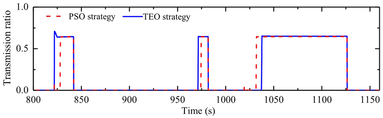
Transmission ratio.

Battery SOC.
Figure 19 shows the engine operating points with the two strategies. Higher efficiency of the system is guaranteed and the internal losses of the system are reduced with the TEO strategy. However, the operating points of the engine are partially distributed along the optimal operating line, most of the operating points are distributed in the economical region, and some of the operating points are distributed in the low-efficiency region. The engine operating points have been significantly improved with engine torque optimization. In the range between 945 and 1700 r/min, the engine operating points are more concentrated after the PSO optimization. In the range between 1700 and 2300 r/min, the engine operating points are mainly concentrated between 230 and 240 g/(kW h) under the TEO strategy without engine torque optimization. Although the engine operating points are mainly concentrated between 230 and 260 g/(kW h) under the TEO strategy with engine torque optimization, the torque distribution of the engine is more reasonable. Consequently, the sum of the fuel consumption of the engine and the energy loss of the system are also smaller. In addition, the operating points of the engine above 300 g/(kW h) are greatly reduced with the PSO optimization, which contributes to the reduction of vehicle fuel consumption.

Engine operating point.
Figure 20 compares the input energy of the engine and the battery. The input energy of the engine and battery without PSO optimization are 12,971.7 and 825.95 kJ, respectively. The input energy of the engine and battery with PSO optimization are 11,902.1 and 782.9 kJ, which are decreased by 8.25% and 5.21%, respectively.
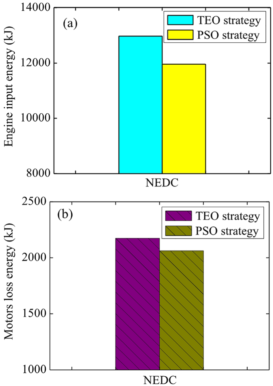
Vehicle input energy.
Figure 21 compares the energy losses of different components. The proportion of the engine energy loss is the largest among all the components. Engine losses are 8334.6 and 7655.5 kJ under two control strategies, respectively. Engine loss is decreased by 8.15% with the PSO optimization. The energy loss of the battery is about 637.76 kJ without engine torque optimization and is decreased by 79.36 kJ when the engine torque is optimized by the PSO strategy.

The components loss energy.
Table 4 shows the simulation results under the two strategies. The engine fuel consumption per 100 km is 3.31 L when the engine output torque is optimized by PSO algorithm, and the equivalent fuel consumption per 100 km of the engine is 3.76 L. Compared with the results without engine torque optimization, the equivalent fuel consumption of the vehicle is reduced by 10.26%. Simulation results show that the battery SOC fluctuates within a reasonable range. The fuel economy of the vehicle is further improved by optimizing the engine operating points with the PSO algorithm under the premise of ensuring high transmission efficiency.
Comparison of simulation results.

SOC: state of charge; TEO: transmission efficiency optimization; PSO: particle swarm optimization.
Conclusion
Aiming at a novel power split HEV with dual planetary gear sets, the speed and torque relations between different components are systematically established based on the lever analogy. The power split mechanism and transmission efficiency of the vehicle are analyzed, which provide a basis for the design of the control strategies.
The TEO control strategy based on the optimal transmission efficiency of the hybrid system is designed. In order to optimize the engine operation points under the TEO control strategy, the torque distribution of the engine is realized by fuzzy controller, and the fuzzy membership functions and fuzzy rules are optimized by PSO. Finally, the control strategy and vehicle model are integrated and jointly simulated. The results of the co-simulation show that the operating points of engine and two electric machines are optimized by the PSO algorithm; the final value of the battery SOC is kept within a reasonable interval. The equivalent fuel consumption of the whole vehicle is reduced by 10.26% compared with the TEO control strategy without PSO optimization.
Footnotes
Handling Editor: Pedro Piqueras
Declaration of conflicting interests
The author(s) declared no potential conflicts of interest with respect to the research, authorship, and/or publication of this article.
Funding
The author(s) disclosed receipt of the following financial support for the research, authorship, and/or publication of this article: This study was supported by the National Nature Science Foundation of China (grant nos 51475213, U1764257), the Foundation for Jiangsu Key Laboratory of Traffic and Transportation Security (grant no. TTS2018-01), and the “333 Project” of Jiangsu Province (BRA2018178).