
Abstract
A new approach for cylindrical blade design is presented in this article. Authors of this article analyzed the main reasons which are responsible for the low efficiency of untwisted blades and found out that the shock losses along the blade leading edge are much higher than those of twisted blades. Furthermore, based on the analysis, this article proposed a new design approach that is different from the traditional one. This new approach can reduce hydraulic losses at blade leading edge and improve performance and efficiency of cylindrical blades. In the traditional design process, to draw blade projection in plan view, an incidence at intersection of blade leading edge and inner streamline on the meridional section is selected for calculating blade inlet angle accurately. Because the incidence and the blade inlet angle at the intersection of blade leading edge and outer streamline are formed automatically, the blade inlet angles at this point are not suitable for oncoming flow direction, generating noticeable shock losses at this place. In the new design program, blade inlet angles at both intersection points formed by blade leading edge and the outer, inner streamlines are accurately calculated. This makes the shock losses generated by blade leading edge be minimized. Moreover, in conventional design, the projection of blade pressure side into plan view consists of only one plane curve. In the new design way, projection of blade surface in plan view is composed of two curves joined smoothly and continuously. Two impellers with fundamentally identical geometrical parameters were designed and manufactured, and the only difference is that their cylindrical blades were calculated and configured by applying a traditional design method or a the new approach. Test findings from an open loop indicate that in a wide load range from 0.8 to 1.2 times design flow rate, both head and efficiency of the new pump were raised. Over the operating range, efficiency of the new pump increased by 0.5% to 2.7%. Particularly, for higher flow rate, pump performance was improved significantly, and the increase of efficiency at pump design point arrived at 2.7%. The results suggest that the new approach presented in this article offers an effective and useful means to improve performance of low specific speed pumps.
Introduction
Cylindrical blade is a fundamental blade form applied to low specific speed impellers. Its hydraulic performance is basically determined by the blade geometry. A large body of literature has reported the methods to reduce hydraulic losses incurred by the blades. JF Gülich 1 and Lobanoff 2 proposed guidelines to establish blade geometrical parameters for impellers of different specific speeds and described detailed procedures to configure single circular arcs as the projection of untwisted blades in plan view. For widening high efficiency load range of a low specific speed pump, J Pei et al. 3 selected different magnitudes of blade outlet width, blade outlet angles, and blade wrap angles to configure several impellers and compared their performance. DS Zhang et al. 4 simulated the flow field within 10 low specific speed impellers and proposed solutions to improve their efficiencies. B Jafarzadeh et al. 5 presented a general three-dimensional simulation of turbulent fluid flow for a low specific speed impeller and investigated effects on pump best efficiency of blade number and position of blades with respect to volute cutwater. T Wang 6 simulated the turbulent flow in the waterways of a low specific speed impeller and discovered the differences of flow behaviors at pump design point and off-design conditions. E Dick 7 offered a number of empirical formulas to estimate hydraulic losses generated in different locations within a centrifugal impeller. Authors of this article derived polar coordinate equations for some plane special curves suitable for projections of cylindrical blade surfaces.8–11 They also proposed a new kind of cylindrical blade and its wrap angle can be specified by designers to meet requirements, while this important geometrical parameter is decided by blade inlet and outlet boundary conditions in other design principles. 12 These publications have all contributed to the improvement in blade performance.
Advanced design approaches and ideas are the bases to develop products of high performance. Published data have shown that when other geometries remain unchanged, the efficiencies of impellers with cylindrical blades are lower than those of pumps with twisted blades, and at design flow rate, the difference can reach 2.5%. The reduction in efficiency arises from the traditional design principles and methods related to cylindrical blades. This article will present a new design approach for untwisted blades and discuss the sources of hydraulic losses. This new approach is different from the traditional methods in the calculating process and could become a new design tool for blade designers.
Conventional design way for cylindrical blades and outlines of hydraulic losses generated in blades
The geometrical structure of a cylindrical blade is decided by its meridional section and plan view in a plane perpendicular to the impeller axis. These two views can determine not only the blade shape, but also its hydraulic performance. In the conventional blade design practice, the blade drawing procedures are as follows:13,14 based on the main blade geometrical parameters established previously, the meridional section of the blade was drawn with blade leading edge, as shown in Figure 1. In the plan view, projections of the two intersections between blade pressure side, impeller front and rear shrouds, projection of blade pressure side itself are three overlapped plane curves. The projections corresponding to the twisted blade do not show such features. As the intersection between blade pressure side and impeller rear shroud has the maximum wrap angle, in the traditional cylindrical blade design practice, to draw the blade pressure side in the plan view is actually to draw the projection of the intersection. Thickening the plane curve described above in accordance with design guidelines yields the another plane curve which represents the projection of blade suction side in the plan view. To draw the projection of the intersection between the blade pressure side and the rear shroud, the geometrical parameters of intersection, and only these parameters, must be applied. These include radius RB at point B, which is the intersection point of the blade leading edge and the rear shroud, the blade outlet radius R2, which is also the impeller radius, the blade angle β2 at the intersection outlet RB, R2 and β2 are unchanged in the plan view. The projected angle β1B(t) of the blade angle β1B at point B is also used. In the plan view, the projected curve must satisfy the following boundary conditions. The plane curve lies between two concentrical circles with radii of R2 and RB. At the intersection points of the plane curve and two circles, two angles between the tangential directions of the curve and peripheral directions of circles are β2 and β1B(t). The projection of blade pressure side in the plan view is illustrated in Figure 1.

Two views of pressure side of a cylindrical blade.
An important idea involved in the traditional untwisted blade design process is that, in the plan view, the projection of the intersection line formed by the blade pressure side and the rear shroud is applied to represent the blade pressure side. In the design process, in order to draw the blade pressure side in the plan view, the blade angle β1B at point B, the intersection point of the blade leading edge and the rear shroud, must be calculated first. Also, its projected value β1B(t) must be achieved. As a result, the blade angle at point B of the accomplished blade can match the approach flow at the design point, and no shock losses are incurred here. However, the blade angle at point A, the intersection of the blade leading edge and the front shroud, is formed naturally and its value is unknown during the design. As a result, when impeller operates at the design point, blade angles at point A and its neighboring parts along the blade leading edge are not suitable for the oncoming flow. The incidences, which denote the difference between the blade inlet angle and the flow angle, cannot meet the required flow conditions. Notable shock losses are generated along the blade leading edge as flow separation frequently occurs here, causing energy dissipation eddies. 15 However, the blade inlet angles along the blade leading edge of twisted blades have the same directions as the oncoming flow, and shock losses are thus reduced significantly. This is the main reason why hydraulic efficiencies of cylindrical blade are lower than those of twisted blades. In addition, the blade suction side near point A is a region of low pressure. Excessive shock losses at this point reduce water pressure further, making cavitation bubbles more likely occur. The higher the specific speed of an impeller, the broader the impeller passages will be, and the effects of undesired incidences are more remarkable. This is also the reason why applications of cylindrical blades are limited for medium and high specific speed impellers.
New design principles and approaches for cylindrical blades
In order to increase the efficiency of cylindrical blades and minimize hydraulic losses caused by the blade leading edge, this article will present a new design approach for the cylindrical blade. In the new program, blade incidences at the two intersection points formed by the blade leading edge and the two impeller shrouds will be determined by designers.
In order to achieve the expected results mentioned above, the following design procedures should be followed for calculating and drawing the untwisted blades:
1. Based on the main blade geometrical parameters established previously, draw the blade meridional section. Modifications may be necessary until a satisfactory section is achieved. The parameters include impeller radius R2, blade outlet width B2, and impeller eye radius R0. Next draw the blade leading edge AB in the accomplished meridional section following guidelines and experience. Measure the distances RA and RB, from points A and B to the impeller axis. In general, there should be RA > RB, as illustrated in Figure 2.
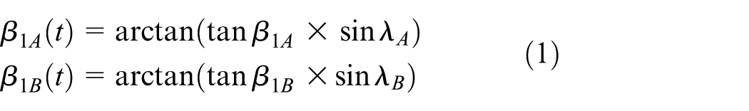
2 .Specify the two blade incidences ΔβA and ΔβB at points A and B. In terms of given design flow rate, impeller rotative speed, and incidences, calculate the blade inlet angles β1A and β1B by trial and error. When the pump operates at the design point, the differences of the blade angles and relative flow angles will be equal to the given incidences at points A and B. This approach is different from the traditional design practice for cylindrical blades, where incidence at point A is not given, and blade angle is not calculated at this point. Consequently, the blade angle and the incidence at point A are established randomly, both of which are unknown before and even after the impeller is made. This is a key difference between the conventional and new design methods.
3. Measure angles λA, λB between the two horizontal lines passing through points A, B and two tangents to the front and rear shroud in the blade meridional section as shown in Figure 2. The purpose of the measurements is to decide the projected angles β1A(t) and β1B(t) of blade inlet angles β1A, β1B. Both projected angles in the plan view are smaller than blade angles
4. There are significant differences between the new approach presented in this article and the traditional one about drawing the projected curve of the blade pressure side in plan views. As stated in previous sections, in the traditional way, the actual drawing process consists of drawing a projected curve of the intersection of blade pressure side and rear shroud in the plan view, while in the new way, the projection of the blade pressure side itself will be drawn. Assume a straight line passing through point A in Figure 2, which is parallel to the impeller axis. This line represents a cylindrical surface with radius RA and is concentrical with the impeller axis. This cylindrical surface divides the blade pressure side into two surfaces, and their projections in the plan view should be drawn separately. In the plan view, the projection of blade surface, two projected curves of intersections between the blade pressure side, impeller front and rear shrouds are three overlapped plane curves. To draw the projections of the upper and lower blade pressure sides in the plan view means to draw the intersections formed by the two blade surfaces, impeller front and rear shrouds. Draw three concentrical circles with radii R2, RA, and RB, where R2 > RA > RB (in the traditional design process, circle RA is neglected). The projections of two blade pressure side portions in the plan view should be configured between circles R2, RA and circles RA, RB.
5. Draw a projected plane curve between circle RA and circle RB in the plan view which represents the projection of the lower portion of blade pressure side. Actually, this drawing process involves drawing the projection of intersection of the lower blade pressure side and rear shroud. The plane curve must satisfy the following boundary conditions. The radii at the two end points of the curve should be equal to RA and RB. At these two points, the plane angles between tangents to the curve and circumferential directions are equal to β1A(t) and β1B(t). It is recommended that an equal changeable angle logarithmic curve should be applied with the following polar coordinate equation

where φ1 denotes the wrap angle of the plane curve, which can be found by application of the following equation


Blade meridional section.
Since β1B(t), β1A(t), RA, and RB are established previously, wrap angle φ1 can thus be obtained using equation (3). Substituting φ1 into equation (2) and giving a series of θ values in the range from 0° to φ1 yield the corresponding values of r in equation (2). Plot a curve passing all points determined by their coordinates

An equal changeable angle logarithmic curve at inlet of blade pressure side projection.
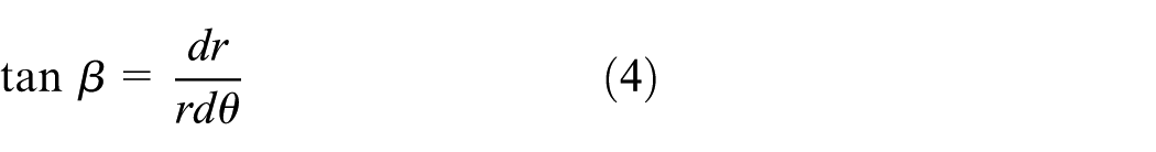
Equal changeable angle logarithmic curve offers a notable advantage. Along the curve, angle β, which is defined as the angle between the tangent to the curve and the circumferential direction at the same point on the curve, will vary with θ, and when θ varies from 0° to φ1, β varies from β1B(t) to β1A(t) linearly. This conclusion can be shown as follows. It is well known that at a given point on a curve, angle β, the radius r of the point, and its derivative
Performing logarithmic calculation for both sides of equation (2) gives

As both sides of the equation above are functions of θ, differentiating both sides with respect to θ yields

Combing the equation above with equation (4) gives
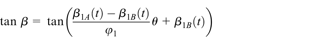
that is
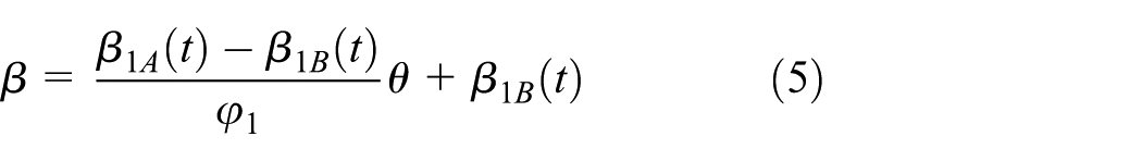
Equation (5) indicates that when θ increases from 0° to
In addition, equation (2) implies that when

Logarithmical calculation of the expression above gives

Substituting equation (3) into the above equation gives

that is, when
The analysis presented above shows that the plane curve determined by equation (2) satisfies all given boundary conditions, and the plane angle β variations along blade leading edge are desirable. It is safe to say that the hydraulic performance of the new cylindrical blades is preferable to the traditional blades where the blade angle is controlled only at one point.
6. Draw a projected curve between circle RA and circle R2 in the plan view, which represents the projection of the upper portion of the blade pressure side in plane. Actually, this drawing process involves drawing the plane projection of the intersection of the upper blade pressure side and the front shroud. The plane curve must satisfy the following boundary conditions: the radii at the two end points of the curve equal RA and R2. At these two points, the plane angles between tangents to the curve and circumferential directions are β1A(t) and β2. It is recommended that a Hermite interpolating function should be applied to configure the plane curve, as shown in Figure 4. This curve can pass through all fixed points in a plane, and directions of tangents to these points on the curve can be given. In addition, the wrap angle of the curve can be specified based on requirements.

Hermite interpolating curve at outlet of blade pressure side projection.
Based on the statistical data, the product of blade number z, blade warp angle φ, and impeller specific speed NS (where
Relationship between

For z and NS are determined previously, the complete blade wrap angle φ can be achieved based on Table 1. The wrap angle φ2 of Hermite interpolating curve is

Obviously,

It can be shown that the curve defined by equation (6) satisfies all the given boundary conditions. When
With β1A(t), β2, RA, and
Connecting the two curves of equal changeable logarithmic curve and Hermite interpolating curve to form the projection of the blade pressure side in the plan view, as shown in Figure 5. At the intersection point of the two curves, the radii of both curves are RA, and the angle between the tangent to combined curves and circumferential direction is the same value as β1A(t), which means that at the intersection point the connected curve is continuous and smooth. Follow the design guidelines to thicken the completed plane curve to configure the blade suction side, and accomplish blade drawing in plan view.

Projection of blade pressure side into plan view.
Based on the principles and design process described in this article, authors of the paper modified untwisted blades for a low specific speed impeller (QVX50-26). At the design point, the flow parameters of the pump are as follows: head
The new design did not change the basic dimensions or the meridional section of the impeller, but the projections of the new and original blade pressure sides in the plan view are different, as shown in Figure 6.

Comparison of original and new projection of blade pressure side.
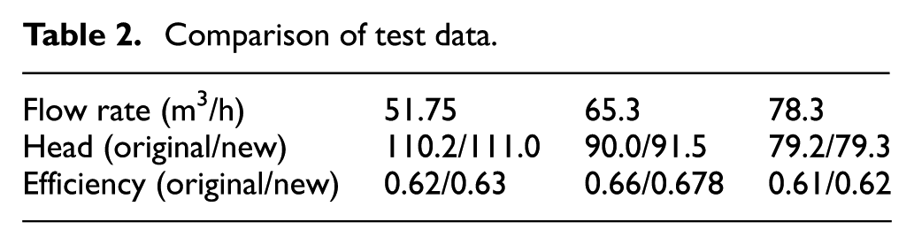
The new blades have the same blade outlet angle and inlet angle at the intersection point of the blade leading edge and the rear shroud as the original blades. The exact blade inlet angle and its projected value at the intersection point of the blade leading edge and the front shroud are calculated, while these two angles are neglected in the original design. The projection of the blade pressure side in the plan view is configured by joining two curves mentioned above. After the impeller with five cylindrical blades was designed, tests for the performance characteristics were done in an open testing loop located in a pump company. The test stand with accuracy of Grade 2 was designed and installed by the Chinese Academy of Agricultural Mechanization. The instruments used in the loop can briefly be described as follows. The flow rates through the system were measured by application of a magnetic flow meter. The head was calculated based on readings of a pressure transmitter. Rotative speed and torque exerted on the pump shaft were obtained by a tacho-torquemeter which joined pump shaft and motor shaft. A regulating valve was mounted at pump outlet side. Flow rates passing through the pump were adjusted by changing opening of the valve. When a three-phase motor was started at nominal rotative speed, set the flow rate passing through the pump at normal flow rate (65.3 m3/h). The head and torque exerted on pump shaft were measured simultaneously. The product of impeller angular rotative speed based on pump rotating speed and torque was defined as the shaft power, while the product of flow rate, head, and specific gravity of water is known as useful power. The pump efficiency at this flow rate is equal to the ratio of useful power to shaft power. All measured values were recorded and transferred to a computer. The operating process was iterated over the range between 0.8 times of design flow rate to 1.2 times of design flow rate under eight designated working conditions. For the values obtained under these working conditions, the computer calculated and displayed the heads and efficiencies automatically, as shown in Table 2. Based on Table 2, it can be seen that when the wrap angle of the new blades remains unchanged, the heads and efficiencies are noticeably improved in a wide load range, and the efficiency increase at pump design point reaches 2.7%. Enlarged Figure 6 shows that in the original design, the blade angle at the intersection point of the blade leading edge and the front shroud is excessively large, making the incidence at this point exceeds the expected value significantly. The impressive shock losses at this point and its vicinity along the leading edge brought about the lowered efficiency of the original impeller.
Comparison of test data.
A 3D blade newly constructed is illustrated in Figure 7

A 3D blade newly constructed.
Conclusion
This article offers a new approach for cylindrical blade calculating and drawing. The new design way presented in this article is characterized by the following features which are different from those involved in the traditional approach:
For the untwisted blade designed by the traditional method, only the blade inlet angle at the intersection point of the blade leading edge and the rear shroud, as well as the incidence, is calculated, while the blade inlet angle at the intersection point of the blade leading edge and the front shroud is formed randomly, where the incidence cannot be controlled. Consequently, at this point and its neighborhood, the blade angles cannot match the approach flow directions. Shock and separation losses generated here become the main reason why the hydraulic efficiency of cylindrical blades is lower than that of the twisted blades. In this article, at the two intersection points of the blade leading edge and the impeller front and rear shrouds, the calculated blade angles create specified incidences. As a result, the improved blade inlet angle distribution along the leading edge reduces the hydraulic losses and the risk of cavitation initiation, which optimizes the cylindrical blade performance significantly.
In the blade plan view, the conventional projection of the blade pressure side is constituted by one curve only, while in the new design approach, the corresponding curve is configured by joining two special curves.
Test data of a modified untwisted blade of a low specific speed impeller based on the new design method revealed that at the design point and its nearby operating range, both heads and efficiencies of the pump are increased, demonstrating the substantial improvement of the new approach for pump design.
Footnotes
Handling Editor: Jose Ramon Serrano
Declaration of conflicting interests
The author(s) declared no potential conflicts of interest with respect to the research, authorship, and/or publication of this article.
Funding
The author(s) disclosed receipt of the following financial support for the research, authorship, and/or publication of this article: This study was financially supported by the National Key Research and Development Program “Research and Application Demonstration of Complementary Combined Power Generation Technology between Distributed Photovoltaic and Cascade Small Hydropower” (2018YFB0905200), Key Laboratory of Fluid and Power Machinery (Xihua University), and Ministry of Education (Grant No. SZJJ2015-41).